A hydraulic system rarely announces a non-return problem neatly. More often, you see the symptom first. A telehandler boom settles when it should hold. A press loses firmness between cycles. A power pack sounds fine on start-up, then a motor line drains back and the next movement is sluggish and rough.
That usually points to one basic fault. Fluid is moving where it shouldn’t.
The hydraulic non return valve is the small component that stops that from happening. It doesn’t generate power, and it doesn’t get much attention until something drifts, back-rotates, chatters or bangs. Yet in both mobile plant and fixed industrial systems, it’s one of the simplest ways to protect pumps, hold loads, maintain pressure and stop reverse flow from turning into a much bigger repair.
The Unseen Guardian of Your Hydraulic System
A common workshop complaint goes something like this. “The ram’s not failed, but it won’t stay put.” In many cases, the cylinder, pump and directional valve all get blamed before anyone checks the non-return valve properly. If that valve isn’t sealing as it should, the system can bleed back internally and the machine starts behaving as though everything is worn out.
That matters more than it first appears. A drifting function on an agricultural machine or mobile plant unit isn’t just annoying. It can affect control, repeatability and safety. On industrial equipment, reverse flow can also upset cycle timing, unload pressure where it should be retained, and create shock when the system restarts.
Why this small valve matters so much
A non-return valve has one job. It allows flow in one direction and blocks it in the other. If it does that cleanly, the rest of the circuit behaves. If it doesn’t, faults start appearing elsewhere and people often chase the wrong cause first.
In practice, a sound non-return arrangement helps with:
- Load holding: keeping a cylinder or motor from creeping when flow stops.
- Pump protection: stopping reverse flow from driving oil back through the pump.
- Pressure retention: maintaining a charged line or section of circuit.
- System stability: reducing the chance of drain-back, delayed response and shock on restart.
Practical rule: If a hydraulic function drifts, hesitates on restart, or allows a motor to back-rotate, check for reverse flow before assuming the pump or actuator is finished.
A long-standing part of UK hydraulic thinking
This isn’t a new idea dressed up in modern terms. During the UK’s Industrial Revolution, early non-return valves were pivotal in the development of steam engines. James Watt’s patented improvements in the 1760s and 1770s boosted engine efficiency by up to 75% compared to earlier models and saved an estimated 7.5 million tons of coal annually by 1800 across UK industries, as outlined in this history of valve development.
The hardware has become more refined, but the principle hasn’t changed. Control the direction of flow, and you control reliability. Ignore it, and small faults become expensive ones.
How a Non-Return Valve Controls Hydraulic Flow
The easiest way to think about a hydraulic non return valve is as a one-way turnstile for oil. Flow in the correct direction opens it. Pressure from the wrong direction closes it.
That sounds basic, but the detail matters because the valve isn’t manually operated. It reacts automatically to differential pressure across its internal sealing element.
What happens inside the valve
Most hydraulic non-return valves use the same core parts:
- Body: the pressure-containing housing with ports and flow path.
- Seat: the sealing surface the closure element presses against.
- Closure element: usually a poppet, cone or ball.
- Spring: used in many designs to keep the valve shut until inlet pressure exceeds the set opening force.
When upstream pressure rises enough, it overcomes the spring force and any downstream pressure acting against the closure element. The valve opens and oil passes through. When pressure equalises, drops away, or reverses, the spring and reverse pressure push the element back onto its seat.
That closing action is what stops backflow.
Why cracking pressure matters even in simple circuits
The opening point is called cracking pressure. That’s the minimum pressure needed to unseat the closure element. Too high, and the valve adds avoidable resistance and heat. Too low, and it may not stay stable in a circuit with fluctuating flow or load reversals.
A lot of service issues come from treating the check valve as a generic fitting rather than a component with dynamic behaviour. In a drain-back prevention role, a low cracking pressure may be ideal. In a load-holding or motor protection role, seat design, closure stability and reverse sealing matter much more.
A short visual can help if you want to see the opening and closing principle in motion:
What the valve is really controlling
People often say a non-return valve “controls flow”. Strictly speaking, it controls flow direction by responding to pressure conditions. That distinction matters. It isn’t a flow control valve, and it won’t correct poor hose sizing, unstable pump supply or a badly damped circuit.
A non-return valve works best when the rest of the circuit is already sensible. It can prevent reverse movement, but it can’t rescue a system with poor flow paths, contamination or bad transient behaviour.
When a valve opens and closes cleanly, the system feels crisp. When it hovers near its cracking point, gets hit by sudden reversals, or sees aerated oil, it may chatter, leak internally or wear the seat. That’s where valve type and specification start to matter.
Exploring the Main Types of Non-Return Valves
Not all non-return valves behave the same in service. Two valves can both “stop backflow” on paper and still perform very differently once they’re fitted to a real machine. The difference usually comes down to the closure element, the seat, the spring arrangement and whether the valve can be opened deliberately by pilot pressure.
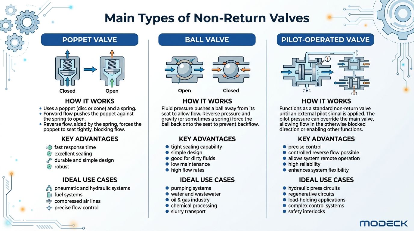
Ball type valves
Ball check valves are simple. A ball lifts off its seat when forward pressure is high enough, then returns to block reverse flow when pressure reverses or falls away.
They’re often compact, straightforward and cost-effective. For basic anti-backflow duties, they do the job well. They can suit compact assemblies, simpler mobile circuits and applications where a small footprint matters.
Their limits show up in finer sealing and dynamic control. A ball can be more sensitive to contamination and seat damage, and in circuits with unstable flow it may not behave as cleanly as a well-guided poppet design.
Poppet type valves
Poppet or cone-type non-return valves generally seal better and close more positively. The moving element is guided, which helps alignment on the seat and often improves repeatability.
That makes them a better choice where internal leakage needs to stay low, where pressure is higher, or where circuit stability matters more than the lowest purchase cost. In practical terms, these are often the safer choice for pump protection, motor circuits, pressure retention and more demanding industrial service.
Some designs use metal-to-metal sealing. Others use soft sealing elements depending on the duty. Metal seats tend to tolerate pressure and temperature variation well, but seat condition becomes critical. Soft sealing can improve shut-off in some applications, but fluid compatibility and long-term wear need watching.
Pilot-operated valves
Pilot-operated non-return valves are for jobs where free flow is needed in one direction, positive blocking is needed in the other, but the blocked side must also be released on command.
That’s the difference. A standard check valve opens only when line pressure acts in the allowed direction. A pilot-operated version can also be overridden by pilot pressure from another part of the circuit.
For holding cylinders or preventing unwanted movement on mobile machinery, that’s often the right answer. According to Wandfluh valve data, pilot-operated non-return valves such as the NG4-Mini offer working pressures up to 350 bar with leakage-tight seats of less than 0.15 ml/min. That low leakage is why they’re so useful for preventing actuator drift or pump back-rotation in mobile plant.
If a load must stay put until another circuit actively commands release, a pilot-operated non-return valve is usually a better fit than a standard inline check valve.
Where each type tends to work best
The table below is a good starting point when narrowing down valve style.
| Valve Type | Sealing Method | Typical Cracking Pressure | Best For | Common Application |
|---|---|---|---|---|
| Ball | Ball against seat, usually spring assisted | Low to moderate, application dependent | Simple anti-backflow duties, compact circuits | Basic inline pump and return protection |
| Poppet | Guided poppet or cone against seat | Low to moderate, application dependent | Better shut-off, higher integrity sealing, demanding duty | Motor lines, pressure retention, industrial power units |
| Pilot-operated | Check valve seat with pilot release function | Application dependent, plus pilot release requirement | Load holding with controlled release | Cylinders on mobile plant, actuator locking, anti-drift circuits |
The trade-offs that matter in the workshop
The wrong choice often still “works” during a bench test. Problems show up later.
- Choose a ball valve when the duty is straightforward and packaging is tight, but don’t expect it to behave like a load-holding valve.
- Choose a poppet valve when seat integrity, repeatability and pressure capability matter more than lowest cost.
- Choose a pilot-operated valve when a suspended or pressurised function must stay locked until another signal releases it.
The key mistake is using a standard non-return valve where controlled release is required, or using a load-holding type where the circuit really needs fast, low-restriction directional control. Both errors lead to the kind of faults that get blamed on everything else first.
Understanding Key Valve Specifications
A non-return valve can look fine on the drawing, pass a quick bench check, and still cause trouble once the machine sees real pressure transients. That is why the specification sheet needs reading as a behaviour guide, not just a size and pressure summary.
For MRO and OEM work, four specifications usually decide whether the valve will stay reliable in service. Cracking pressure, pressure rating, flow capacity, and seat or seal construction.
Cracking pressure
Cracking pressure is the pressure needed to lift the sealing element off its seat and start flow. It affects response, leakage resistance, and how the valve behaves when pressure fluctuates around the opening point.
Parker’s UK literature for the RHD series lists cracking pressures from 0.2 to 6 bar in one product family, which is a good reminder that there is no universal setting for a hydraulic non-return valve. Low cracking pressure helps responsiveness and keeps pressure loss down. It also makes the valve more sensitive to vibration, pulsation, and brief reversals in pressure.
That matters most in circuits with pump ripple, fast directional changes, or long pipe runs. Under those conditions, a valve set too lightly can chatter on the seat. Chatter is not just a noise issue. It hammers the seat, heats the oil locally, and shortens service life.
Maximum operating pressure
The maximum operating pressure is the continuous pressure the valve body, seat, and internals are designed to withstand. It is only part of the picture.
A valve rated to 420 bar may still have a hard life if the circuit sees repeated spike loading above the steady-state figure. Pressure transients from sudden actuator stops, pump compensator action, or fast solenoid switching can momentarily load the valve far more aggressively than the nominal system pressure suggests.
In practice, catalogue selection often goes wrong. Engineers often match the valve to the relief setting and stop there. In the field, I am more interested in what happens during the first 200 milliseconds after a line is opened or shut. If the valve closes hard against a reversing flow front, seat damage and spring fatigue show up long before the body pressure limit is reached.
Flow velocity and cavitation risk
Flow rating needs the same care. A valve can survive the pressure and still be the wrong size hydraulically.
Parker notes flow velocities up to 8 m/s for this type of valve, with cavitation risk increasing when pressure drop and flow conditions are poor. The practical lesson is simple. Check line velocity, not just litres per minute on the datasheet.
An undersized valve drives up internal velocity and pressure loss. Under transient flow, that can produce noise, instability, and localised erosion around the seat and flow path. On test rigs and power units, this often appears as a sharp buzz or crackle just before the valve settles.
Workshop check: If a non-return valve is noisy, hot, or leaves polished wear marks on the internals, check transient flow conditions and line velocity before blaming dirt alone.
Materials and sealing choices
Material and sealing choice decide how well the valve copes with the fluid, the environment, and the way the valve closes under load.
- Carbon steel bodies suit many industrial mineral oil systems where corrosion is controlled.
- Stainless steel bodies make more sense for washdown areas, outdoor equipment, or aggressive environments.
- Metal-to-metal seats tolerate high pressure and repeated shock loading, but they need good cleanliness and accurate seating.
- Elastomer-sealed designs usually give better shut-off at lower pressures, but seal compatibility with fluid and temperature must be checked carefully.
Transient conditions matter here as well. A soft sealing element that gives excellent shut-off in steady service may degrade quickly if the valve is slamming shut against repeated pressure spikes.
Mounting and connection format
Connection style affects reliability more than many catalogues admit. Inline valves, cartridges, sandwich plates, and manifold-mounted designs all do the same basic job, but they do not behave the same way once vibration, pipe strain, and maintenance access are involved.
A long inline valve on unsupported pipework is more likely to see vibration-related loosening or body stress. A cartridge in a well-machined manifold usually handles dynamic loading better, but only if the cavity is made correctly and kept clean. The right mounting choice reduces nuisance failures that get mistaken for valve defects.
How to Choose the Right Valve for Your Application
Good valve selection starts with the failure you’re trying to prevent, not the catalogue page you happen to open first. Ask a practical question. What must not happen when flow stops, reverses or spikes?
That changes the answer quickly. Preventing drain-back to tank is one job. Holding a loaded cylinder securely is another. Protecting a reversible gear motor from unwanted reverse flow is different again.
Mobile machinery needs a tougher valve than the schematic suggests
Agricultural, construction and materials handling machines create awkward conditions for a hydraulic non return valve. The machine vibrates, oil temperature swings, loads reverse sharply and the valve body often lives in a dirty environment.
For mobile applications, prioritise:
- Secure sealing under vibration: a valve that benches well but chatters on the machine won’t last.
- Compact packaging: inline and cartridge styles often make sense where space is limited.
- Controlled opening behaviour: low enough cracking pressure for responsiveness, but not so low that the valve becomes unstable.
- Load-holding logic where needed: if the function must stay locked until pilot release, use a pilot-operated type rather than trying to force a standard check valve into that role.
On tractor and telehandler circuits, preventing back-rotation and actuator drift is usually more important than shaving a small amount of initial cost. A cheap valve that allows creep or unstable closure quickly becomes the most expensive item in the line.
Industrial systems reward stability and low losses
Fixed industrial systems usually give you more control over mounting and layout, but they punish poor component matching through heat, inconsistency and cycle issues.
In presses, power packs and manufacturing plant, I’d normally push selection towards:
- High-cycle seat integrity
- Low pressure drop at the normal working flow
- A body style that suits manifold or clean inline installation
- Predictable behaviour during repeated starts and stops
If the valve sits near a pump outlet, motor branch or pressure-holding line, focus on its dynamic behaviour, not just its static rating. A stable valve with a clean closure characteristic often gives better service than one that looks superior on pressure alone.
A simple selection sequence that works
Use this order and most poor matches get filtered out early:
-
Define the failure mode
Are you preventing drift, drain-back, reverse motor rotation, line depressurisation or shock? -
Check pressure duty
Match normal operating pressure first, then consider what happens during switching, stopping and load reversal. -
Match the flow path
Don’t undersize the valve body and assume pressure rating covers it. -
Choose the valve style
Ball, poppet or pilot-operated, based on the actual function. -
Check environment and serviceability
Corrosion risk, contamination exposure, access and mounting all matter.
A valve that is slightly overbuilt in seat integrity but correctly matched to the circuit will usually outlast a nominally cheaper option chosen on thread size alone.
The strongest selections come from looking at the whole circuit. If you only match thread, pressure and price, you’ll miss the operating conditions that cause the failures people call “mystery faults”.
Installation and Maintenance Best Practices
A correctly selected valve can still fail early if it’s installed carelessly. Most non-return valves aren’t complicated to fit, but they are unforgiving of dirty assembly, wrong orientation and poor commissioning.
The first check is the simplest one. Confirm the flow direction arrow on the body matches the intended direction of free flow in the circuit. It’s an obvious point, yet reversed installation still turns up regularly in repair work.
Installation points that prevent avoidable trouble
Use a clean process from the start. Any swarf, seal debris, thread contamination or damaged tube end can stop the valve seating properly from day one.
A practical installation routine should include:
- Confirm orientation: align the body arrow with the permitted flow direction.
- Inspect ports and fittings: any burr or damage can contaminate the seat immediately.
- Keep lines clean: cap open hoses and tubes until final assembly.
- Use the correct mounting style: don’t force an inline valve into a stressed pipe run that transfers vibration into the body.
- Commission slowly: bring pressure up in a controlled way and listen for chatter or abnormal noise.
What to watch during service
A non-return valve usually gives warning before complete failure. The signs are there if someone looks for them during routine checks.
Watch for:
- External leakage: around ports, body joints or damaged threads.
- Internal leakage symptoms: cylinders creeping, motors drifting, delayed restart or line drain-back.
- Noise: chattering, hammering or a repeated clicking under changing flow.
- Heat: a valve that runs unusually hot may be undersized, unstable or partly obstructed.
- Slow response: if an actuator hesitates before movement, trapped or drained flow paths may be involved.
Maintenance that actually helps
Routine maintenance on these valves isn’t about constant strip-down. It’s about keeping the surrounding system healthy.
Keep the oil clean, keep the filtration doing its job, and many non-return valves will last far longer than the average breakdown investigation assumes.
That means checking filtration condition, fluid cleanliness, hose condition and whether the valve is still seeing the duty it was chosen for. If a machine has been modified, sped up or repurposed, the original valve choice may no longer be right even if the valve itself is not damaged.
When replacement is needed, swap like-for-like only after confirming the original specification was suitable. Repeating a bad choice is a common way to create repeat failures.
Troubleshooting Failures Beyond Simple Wear
When a non-return valve fails, wear is the first explanation people reach for. Sometimes that’s correct. Often it isn’t the full story.
A lot of check valve damage comes from transient flow conditions. That means rapid starts, sudden stops, shifting loads, trapped pressure release and flow reversals that happen faster than the valve can settle cleanly. In those moments, the valve isn’t operating in the tidy, steady-state way shown on a schematic.
Why transient behaviour catches people out
Check valves are transient in nature and can react to unsteady flow conditions in unexpected ways. In some hydraulic systems, surge pressures during transient events can exceed 300 bar, which can lead to premature valve failure if selection doesn’t account for it, as discussed in this transient check valve webinar.
That’s where newer valves can still fail. The seat gets hammered. The closure element chatters. The spring sees repeated shock loading. The body may survive the nominal pressure perfectly well while the internal sealing surfaces degrade much earlier than expected.
Symptoms that point to transient damage
If the valve keeps being replaced but the same problem returns, stop blaming age alone. Look for signs that the circuit is producing harsh switching events.
Common clues include:
- Repeated chatter at changeover
- Banging or shock noise when flow stops
- Fresh seat leakage on a relatively new valve
- Damage concentrated around reversing functions or load-holding circuits
- Faults that appear only under live machine movement, not on a static pressure test
What actually fixes it
The fix is often outside the valve itself. You may need to review line size, actuator speed, switching sequence, pressure-limiting strategy or whether a different valve style would close more cleanly in that duty.
A few practical responses usually help:
- move away from a marginal cracking pressure that encourages flutter
- use a valve with stronger closure stability
- review where the valve sits in relation to the source of surge
- check whether pilot-operated load holding is needed instead of a basic check valve
- investigate circuit conditions during stopping and reversal, not just at steady pressure
If you only replace the part and ignore the event that damaged it, the next valve is already on borrowed time.
Your Partner for Reliable Hydraulic Control
A non-return valve often gets judged on catalogue basics, then blamed when a machine bangs on shutdown or starts leaking after a few weeks back in service. In practice, the valve is usually exposing a circuit problem, not creating one. Pressure spikes, poor placement, unstable closure and marginal sizing are what shorten service life in a lot of UK plant and mobile equipment.
That is why valve selection needs to be tied to duty, not just port size and maximum pressure. A check valve that performs well at steady flow can still misbehave during rapid reversals, pump stop events or load-induced pressure surges. Those transient conditions are where chatter starts, seats get marked and repeat failures begin.
Hydraulic demand across UK industry remains strong, but market numbers only matter if they lead to better engineering decisions. For MRO teams and OEM engineers, the practical point is simple. Treat the hydraulic non return valve as a control component that affects load security, restart behaviour, oil temperature and maintenance intervals.
At MA Hydraulics, we help customers identify the underlying cause before another valve goes into the line. That may mean cross-referencing an existing part, but it often means checking cracking pressure, flow path, mounting position, contamination risk and what the pressure trace looks like during switching. A valve can meet the paper specification and still be wrong for the job.
Reliable hydraulic control starts with matching the valve to the circuit behaviour you have on site.
If you need help selecting the right hydraulic non return valve, cross-referencing an existing part, or specifying components for a repair or new build, speak to MA Hydraulics Ltd. Call 01724 279508 today, or send us a message.
