
If you're chasing a hydraulic fault that only appears after the machine has been working for a while, temperature is one of the first things worth watching properly. The awkward jobs are the ones where the unit starts cold, runs acceptably, then gets noisy, sluggish or erratic once the oil warms up. By that stage, the damage often started earlier.
A lot of teams still treat temperature monitoring as a storage or compliance exercise. That mindset is too narrow for hydraulics. In a working circuit, temperature tells you about friction, restriction, cooling performance, internal leakage and whether the machine is drifting towards a failure that will cost far more than a sensor ever will.
Why Temperature Monitoring Is Non-Negotiable for Hydraulics
A common service call goes like this. The power pack runs normally first thing in the morning. A few hours later, actuator speed falls away, the pump gets louder, seals start weeping, and the operator says the machine “just loses its edge” when it's been under load.
That usually isn't a mystery. It's heat.
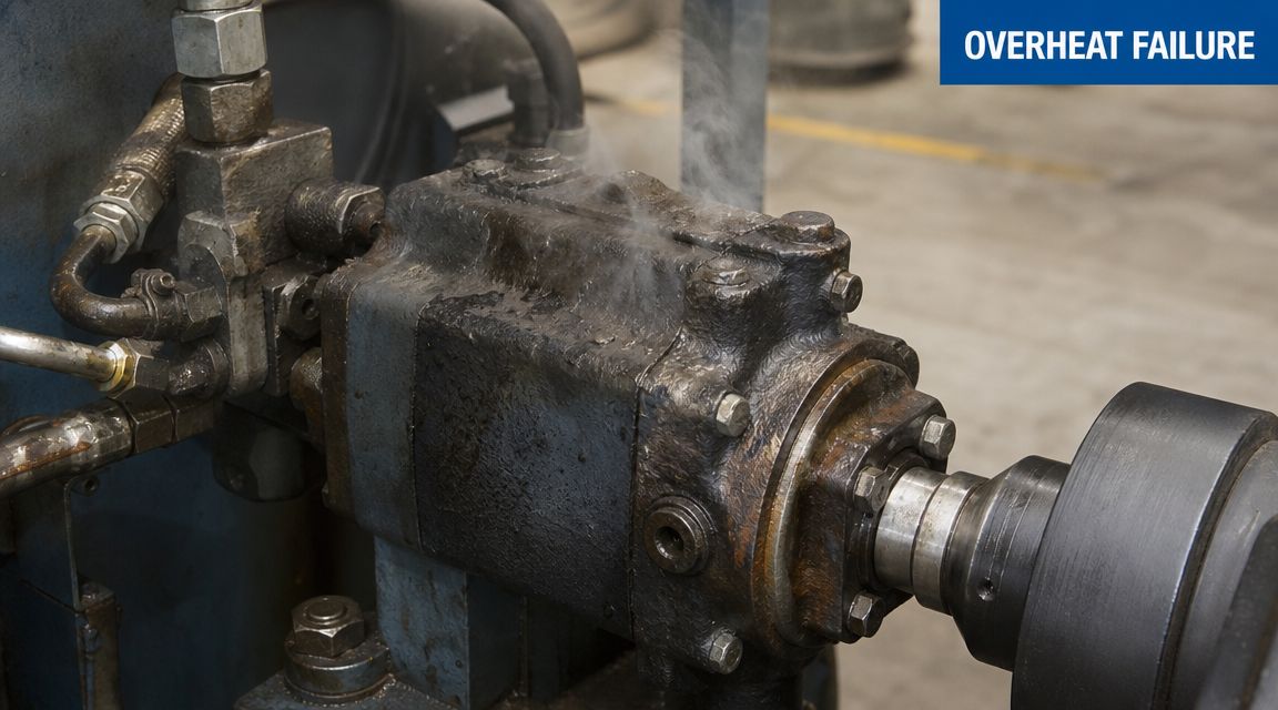
What overheating actually does
As oil temperature climbs, the fluid stops behaving the way the circuit designer intended. Viscosity drops, so the oil film protecting moving parts gets weaker. Internal leakage rises. Pumps lose volumetric efficiency. Valves become less predictable. Seals and hoses are asked to survive in conditions that shorten service life.
The machine might still run, but it won't run cleanly. That matters because operators often judge “working” and “healthy” as the same thing. They aren't.
In hydraulic systems, oil temperature, casing temperature and ambient temperature can diverge sharply, so one reading on its own can hide an emerging fault. The more useful approach is to monitor more than one point, because multi-point monitoring gives earlier warning and is more useful for predictive maintenance than a simple one-sensor check according to the PMC review on temperature monitoring and environmental measurement.
Practical rule: If the reservoir looks fine but the pump body is running hotter than it should, don't trust the reservoir reading to clear the machine.
Compliance tells you less than condition
Basic compliance monitoring asks a narrow question. Is temperature inside an acceptable band, yes or no?
Asset protection asks a better one. Why is this part of the system heating up now, and what is it trying to tell us?
That difference is where a lot of maintenance budgets are won or lost. A single tank probe can confirm bulk oil temperature. It can't tell you much about a partially blocked return filter, a cooler that's underperforming, a pump working harder than it should, or a local hotspot around a bearing housing or casing.
That's why proper temperature monitoring belongs alongside pressure checks, contamination control and vibration awareness. If you're already moving towards condition-based maintenance for hydraulic equipment, temperature should be one of the first condition signals you trust.
What works and what fails
Good practice is simple, but it has to be disciplined:
- Monitor trends, not isolated readings: One handheld check tells you what happened at that moment. A trend tells you whether the system is drifting.
- Look for disagreement between points: Reservoir stable, return line high, and pump casing climbing often tells a more useful story than one absolute number.
- Act early: Heat rarely arrives alone. It usually travels with restriction, poor cooling, air ingress, wrong oil choice, internal wear or excessive slip.
The expensive failures don't usually start as dramatic failures. They start as ignored temperature behaviour.
Selecting the Right Temperature Monitoring Sensors
A sensor choice that looks sensible on paper can be a poor choice on a hydraulic machine. Oil, vibration, contamination, washdown, electrical noise and awkward mounting points all change what works in practice. The first question isn't “which sensor is most accurate in a laboratory?”. It's “which sensor will keep giving believable readings on this machine, in this environment, for the long haul?”.
Calibration matters more than brochure claims
Reliable temperature measurement is built on repeatable standards. Robert Hooke proposed the freezing point of water as a zero point in 1664, and Daniel Gabriel Fahrenheit introduced a formal repeatable scale by 1724, a reminder that the value of any reading depends on calibration and standardised units, as outlined in Dewesoft's history of temperature measurement.
That still applies on the workshop floor. A sensor is only as good as its calibration, and a cheap sensor with poor mounting and no calibration discipline can create more confusion than insight.
What each sensor type is actually good at
Below is a practical comparison. Cost varies by construction, cable type, connector standard, environmental protection and whether you need a transmitter, pocket, thermowell or display. Because no verified pricing data is provided here, treat the cost column qualitatively rather than as a fixed buying guide.
| Sensor Type | Typical Cost (GBP) | Best For | Key Advantage | Key Disadvantage |
|---|---|---|---|---|
| Thermocouple | Varies by specification | Pump casings, metal surfaces, general industrial monitoring | Robust, widely available, fast response | Signal quality can suffer if installation and wiring are poor |
| RTD | Varies by specification | Reservoirs, stable process points, higher-confidence trend monitoring | Strong stability and repeatability when properly installed | Usually more expensive and more sensitive to mechanical abuse than simpler probes |
| Thermistor | Varies by specification | Compact assemblies and tighter-range monitoring | Good sensitivity over a narrower working band | Less versatile across broad industrial conditions |
| Infrared non-contact sensor | Varies by specification | Spot checks on inaccessible or moving surfaces | No contact with the target surface | Surface finish, contamination and line-of-sight issues can mislead readings |
Matching the sensor to the hydraulic point
A sensor should fit the job, not the catalogue.
- Reservoir monitoring: An RTD or a protected immersion probe usually makes sense where you want a stable reading of bulk oil condition.
- Pump casing monitoring: A rugged contact sensor, often a thermocouple style arrangement, is often more practical because the mounting surface is exposed to vibration and local heating.
- High-pressure or return line monitoring: The sensor needs correct wetted compatibility, secure sealing and a mounting method that won't become a leak path.
Don't buy by price alone. If the measurement range, sampling behaviour or installation method is wrong, the reading can be technically “live” and still be useless.
Trade-offs junior engineers usually meet first
There's no perfect sensor. There's only the least problematic choice for the duty.
A few trade-offs come up repeatedly:
- Fast response versus survivability: A delicate sensor may respond quickly, but not for long if it's mounted on a vibrating pump.
- Surface temperature versus fluid temperature: Surface sensors are easier to retrofit, but they don't always tell the same story as immersed probes.
- Simple installation versus serviceability: A quick stick-on solution is tempting until the first washdown, repaint, or cable snag.
- Non-contact convenience versus confidence: Infrared tools are excellent for fault finding and comparison checks, but they're weak as the sole source of automated protection.
If you want one rule to hold onto, it's this. Buy the sensor for the environment first, then for the specification.
Best Practices for Sensor Installation and Placement
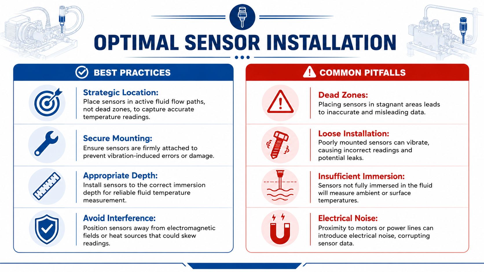
The best sensor in the world can still lie to you if you put it in the wrong place. Most bad temperature monitoring on hydraulic equipment comes from placement errors, weak mounting, shallow immersion or letting ambient conditions influence the reading.
The three locations that usually matter most
If I had to instrument a standard hydraulic unit without overcomplicating it, I'd start with these points:
-
Reservoir
This gives you the bulk oil temperature. It helps you judge the overall thermal state of the system and whether the cooler is keeping up over time.
-
Main pump casing
Local mechanical stress often shows itself earlier. A casing running hotter than the surrounding thermal picture deserves attention.
-
Return line before the cooler
This tells you how much heat the working circuit is bringing back. It's one of the clearest places to see whether the system is generating more heat than it should.
Placement mistakes that distort the picture
A lot of false confidence comes from readings taken in the wrong place.
- Dead zones in tanks: Oil sitting in a stagnant corner won't represent what the system is doing under flow.
- Sensors too close to external heat: Nearby motors, sunlight, hot pipework or enclosures can bias the reading.
- Poor surface contact: A casing probe with a loose clamp or painted mounting area often tracks air temperature more than metal temperature.
- Shallow immersion: If the probe tip isn't properly in the oil, you're partly measuring the headspace, not the fluid.
A believable reading comes from the right thermal contact, not just from a powered sensor.
Installation details that save trouble later
Small details separate a useful installation from a nuisance one.
- Prepare the contact point: Clean away paint, scale and contamination on casing mounts so the sensor sees metal, not insulation.
- Mount firmly: Vibration is normal on hydraulic equipment. Loose sensors won't stay truthful for long.
- Protect the cable run: Keep it clear of chafing points, moving parts and places where oil contamination will soften or foul the sheath.
- Use suitable immersion depth: In tanks and lines, the sensor needs to be far enough into the medium to reflect actual fluid temperature.
- Shield from avoidable interference: Keep wiring away from obvious electrical noise sources where possible.
Think in terms of thermal behaviour
A junior engineer often asks where the “correct” sensor point is. The better question is where the heat will show first for the fault you're trying to catch.
If you suspect cooler underperformance, reservoir and return-line temperatures tell the story. If you suspect pump distress, casing temperature becomes more valuable. If the machine works outdoors or in a draughty bay, ambient influence matters more than many people realise.
Choose positions that reflect the physics of the fault, not just positions that are easy to drill and wire.
Configuring Alarms and Data Logging Systems
A live temperature value on a screen doesn't protect anything by itself. Protection starts when the reading is logged, checked, compared against limits and linked to a response that people follow.
Build the monitoring chain, not just the sensor point
The most defensible approach is a calibrated sensor network with a documented alarm workflow, with continuous recording, routine calibration and a retained audit trail. The important part for engineers is to treat the logger as a full measurement chain, where the sensor, hardware, power and memory all need validation, as described in SafetyCulture's temperature data logger guidance.
That's the part many installations miss. They fit a sensor and assume the job is finished. It isn't.
A logger that loses power, stores incomplete data, drops communication or never gets archived properly creates blind spots that are hard to diagnose after a stoppage.
Set alarm levels that mean something
Use at least two alarm states. One should tell the team to investigate. The other should trigger a protective action.
A practical structure looks like this:
- Warning alarm: This is the “something has changed” level. It should prompt an operator or maintenance technician to check cooler operation, oil level, filter condition, duty cycle or abnormal machine load.
- Critical alarm or shutdown alarm: This is the level where continued running risks component damage. The machine should reduce load, start protective cooling action or shut down in a controlled way.
The exact temperatures have to match the oil grade, component limits and duty of the machine. Copying someone else's setpoint rarely ends well.
Choose a logging interval that captures behaviour
Logging too slowly hides spikes. Logging too fast creates noise, bloated files and alarms that nobody trusts.
A sensible interval depends on how quickly your hydraulic system heats and cools. Fast-cycling machinery, intermittent heavy-duty equipment and compact power packs often need tighter logging than slow, steady industrial systems. What matters is being able to see the rise, hold and recovery pattern.
If the graph can't show how the machine warms under load and settles after load is removed, the logging interval probably isn't useful enough.
Pick the right way to move data
Different plants need different data paths.
- Local USB or manual download: Fine for straightforward fixed assets where someone regularly inspects data and trend reviews are part of maintenance.
- Wi-Fi connected logging: Useful where several assets sit within one site and alarms need to reach a central platform.
- Cellular or GSM telemetry: Better suited to remote plant, mobile machinery or sites where local network access is unreliable.
The right answer depends less on fashion and more on whether the alarm reaches the right person in time, and whether the data is still there when you need to review a fault.
Integrating Monitoring with Hydraulic Control Systems
Monitoring becomes valuable much faster when it does something. A trend line is useful for diagnosis. A linked control action prevents damage.
Start simple if the machine is simple
Not every hydraulic unit needs a fully networked control architecture. On smaller or older machines, a hardwired temperature switch can still do a useful job.
That basic arrangement might:
- turn on a warning beacon,
- drive a panel lamp,
- sound a buzzer,
- energise a cooling fan,
- or inhibit a machine function until temperature falls.
Simple logic often survives harsh environments better than overcomplicated systems. If the machine only needs one protective action, keep it direct.
Use PLC and HMI logic where the process justifies it
Once you've got a PLC in the system, temperature monitoring should be part of the control conversation, not a side display. A PLC can compare reservoir, return and casing temperatures, delay nuisance alarms during start-up, and distinguish between a brief thermal rise and a sustained overheating condition.
That opens up better responses:
- Automatic fan control when oil temperature rises under sustained load
- Load reduction if heat climbs but the process can continue safely at reduced demand
- Controlled shutdown before seals, pumps or valves are pushed into damaging conditions
- Fault messaging on the HMI that tells the operator where the problem sits, rather than just flashing “high temp”
Where control architecture is already part of the build, components such as a hydraulic valve controller for integrated machine logic can sit alongside the wider protection strategy rather than leaving temperature as a standalone afterthought.
Borrow the right monitoring habit from other sectors
Good monitoring practice isn't unique to hydraulics. The same discipline used in software and infrastructure applies here as well. The CloudCops monitoring guide is useful because it reinforces a principle that translates neatly to machinery. Collect data that matters, define clear alert paths, and tie alerts to action rather than dashboards for their own sake.
Hydraulic engineers can use that thinking without adopting software jargon. If an alarm never changes what the machine or the maintenance team does next, it's only decoration.
The strongest monitoring systems don't just report overheating. They reduce the chance that overheating turns into a repair.
Maintenance and Troubleshooting Common Issues
Temperature monitoring only helps if the readings stay trustworthy. Plenty of systems are fitted with good intentions, then slowly become background noise because nobody checks the probe, the cable, the calibration status or the logger health.
The maintenance routine worth keeping
The common gap in many UK monitoring deployments is calibration, traceability and response-time error at the point of use, especially under real conditions such as vibration, airflow and fluid contact. The stronger approach is lifecycle accuracy management, not just initial sensor selection, as discussed in Prosense's review of industrial temperature measurement practice.
That means putting the monitoring system into the maintenance plan, not leaving it outside it.
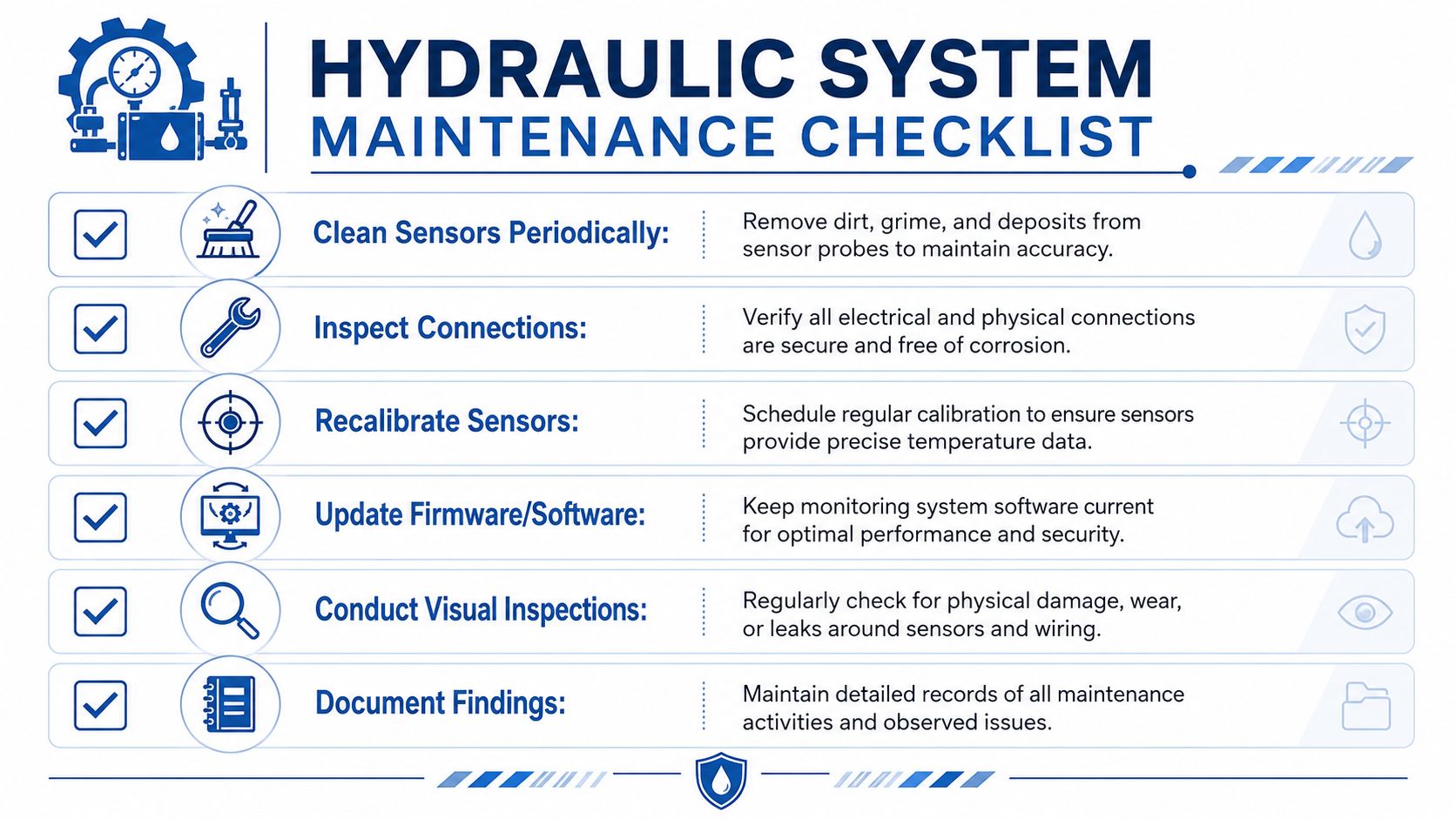
A workable routine includes:
- Clean the sensing point: Oil residue, dirt and buildup can interfere with contact and response.
- Check cable support and glands: Many intermittent faults come from movement, rubbing or oil ingress rather than the sensor element itself.
- Verify mounting security: A slightly loose probe can create readings that drift just enough to waste hours of fault finding.
- Review calibration status: If the value looks wrong, prove the sensor before blaming the machine.
- Check logger health and archived records: Missing data often gets discovered only after a trip or failure.
For teams refining maintenance strategy more broadly, Clouddle's practical maintenance guide is a useful reference on how predictive and preventive approaches fit together. In hydraulics, temperature monitoring works best when it supports both.
What common faults usually mean
Most bad readings fall into recognisable patterns.
- Erratic or noisy reading: Often wiring issues, poor grounding, electrical interference or vibration affecting the connection.
- Reading consistently high: Sensor mounted near an outside heat source, poor placement, or a process issue that's creating excess heat.
- Reading consistently low: Shallow immersion, poor thermal contact, sensor drift or measuring a sheltered cool spot rather than the active fluid path.
- Frequent nuisance alarms: Thresholds are set without regard to warm-up conditions, normal duty cycle or expected transient behaviour.
- Flat trend with no variation: Dead sensor, dead logger channel, failed communications, or a probe mounted where nothing meaningful changes.
The fix isn't always to replace parts immediately. First decide whether the fault is in the machine, the measurement point or the logging chain.
If your team already works to planned servicing schedules, it makes sense to tie sensor checks into preventive maintenance plans for hydraulic equipment. That's usually the easiest way to keep monitoring credible instead of letting it become another ignored screen on the panel.
If you need help diagnosing overheating, specifying practical temperature monitoring points, or matching hydraulic components to a more reliable maintenance strategy, contact MA Hydraulics Ltd. Phone 01724 279508 today, or send us a message.
