
A pump that suddenly sounds like it's processing gravel usually gets blamed for being worn out. The operator may notice heavier vibration, a fluctuating pressure gauge or a loss of flow, then find that a recently replaced pump has developed the same fault. In many UK hydraulic installations, the pump is only where the damage becomes visible. The cause sits upstream, in the suction line, filter, valve, reservoir or operating conditions.
Understanding what causes pump cavitation means following the pressure conditions at the pump inlet. When local pressure falls below the liquid's vapour pressure, the liquid flashes into vapour. Those bubbles then enter a higher-pressure region and collapse, creating the mechanical damage associated with cavitation. The practical response isn't to fit another pump. It's to restore inlet pressure, protect the NPSH margin and remove the restriction or condition that started the problem.
Understanding Pump Cavitation and Its Hidden Damage
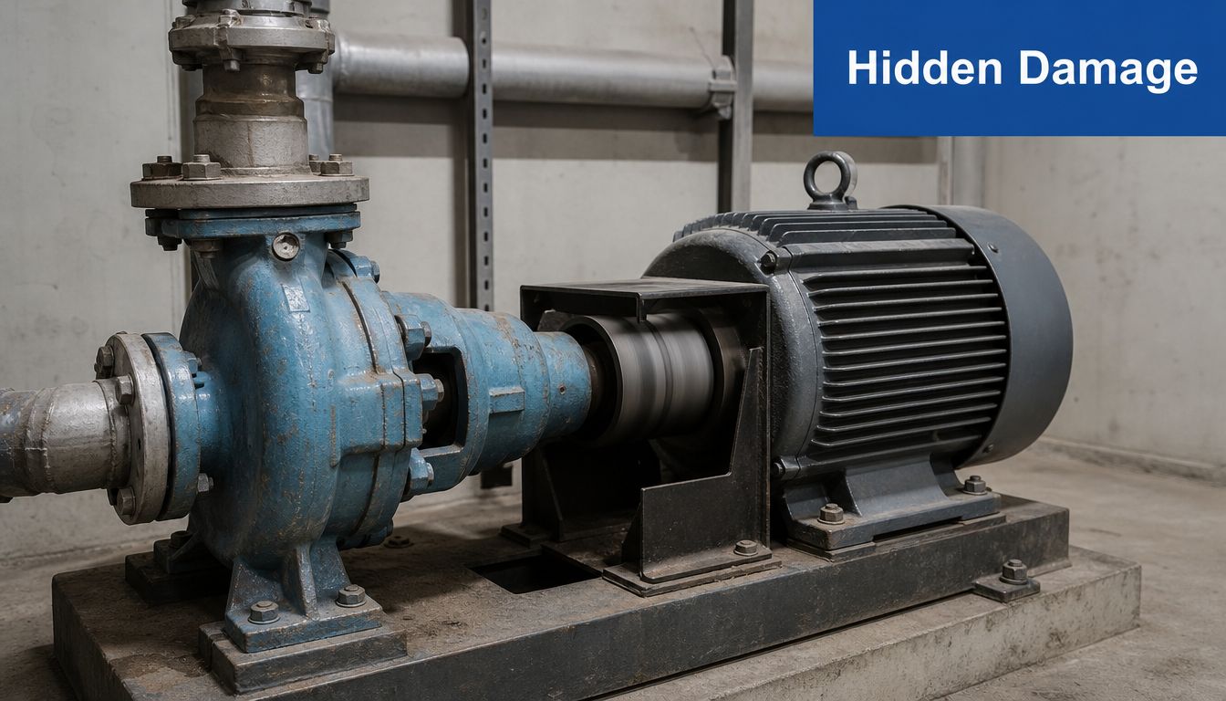
A maintenance supervisor often hears cavitation before seeing it. The pump develops a harsh rattling sound, the casing vibrates, and output becomes unstable. The noise can resemble gravel or marbles moving through the pump, but the source isn't loose material. It's the repeated formation and collapse of vapour bubbles inside the hydraulic passage.
Vapour bubbles become a mechanical problem
The Grundfos UK pump handbook describes the initiating event clearly. Pump cavitation starts when pressure at the inlet or another local low-pressure point drops below the liquid's vapour pressure. The liquid changes phase locally, creating vapour bubbles. As the bubbles travel into an area of higher pressure, they collapse.
That collapse produces the shock loading that pits metal surfaces. In centrifugal pumps, the impeller eye is a predictable hotspot because inlet velocity and local pressure conditions can produce the low-pressure zone where bubbles first form, as explained by Atlantic Pumps' guidance on detecting and preventing cavitation.
The consequences extend beyond the impeller. Repeated vibration can load bearings and seals, while erosion changes the geometry of the hydraulic surfaces. The pump may then deliver less stable performance and become more vulnerable to further damage.
Practical rule: treat a new gravel-like noise as a hydraulic warning, not as an acceptable operating characteristic.
Cavitation isn't the same as aeration
Cavitation creates vapour because pressure falls below the liquid's vapour-pressure threshold. Aeration or air ingress introduces air through a leak, poor plumbing, an incorrectly sized hose or a low reservoir level. Both conditions can cause noise, vibration and erratic flow, so replacing components without checking the inlet path often misses the actual fault.
The distinction matters during diagnosis. A pump can be mechanically sound and still cavitate because a blocked strainer or partly closed valve starves the inlet. The British Pump Manufacturers Association explains the pressure condition behind cavitation, including the need to account for suction-side losses when assessing whether the pump has enough available suction pressure.
Early investigation is cheaper than waiting for visible pitting. Check the suction arrangement, operating temperature, fluid level and valve positions before authorising a pump change. If the replacement sees the same inlet conditions, it can suffer the same damage.
The Physics Behind Cavitation Vapour Pressure and NPSH
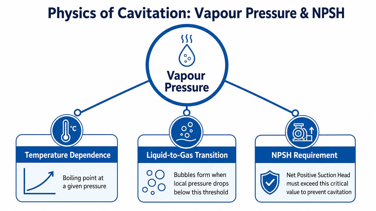
The pressure at a pump inlet doesn't need to reach a vacuum for cavitation to begin. It only needs to fall below the vapour pressure of the liquid at its operating temperature. Vapour pressure is the pressure at which a liquid can begin changing into vapour under the prevailing temperature conditions. As temperature rises, the liquid becomes more likely to vaporise at a given local pressure.
NPSH is the working margin
NPSH, or Net Positive Suction Head, is the hydraulic criterion used to judge cavitation risk. NPSHa is the available suction head supplied by the installation. NPSHr is the suction head the pump requires at a given operating condition. Cavitation risk rises when NPSHa is less than NPSHr, as set out in BPMA guidance on adding up NPSH.
NPSHa depends on the pressure above the liquid, static height, vapour pressure, suction pipework and valve losses. The BPMA's UK guidance says those suction-side terms must be added up when checking whether a pump has sufficient suction pressure. A higher liquid level or greater pressure at the source supports NPSHa. Suction friction, lift and higher vapour pressure reduce it.
Grundfos UK states that, at a given flow rate, available NPSH at the suction port should be at least 0.5 m greater than required NPSH. That margin provides practical separation between the installation's available condition and the pump's stated requirement, rather than relying on a calculation that only works under ideal conditions. The Grundfos UK NPSH explanation also links low inlet pressure with evaporation and subsequent cavitation.
Think about a blocked drinking straw
A pump pulling through a narrow or obstructed suction path behaves like someone trying to drink through a restricted straw. The pump still attempts to draw fluid, but friction and velocity losses consume more of the pressure available before the fluid reaches the impeller. If the remaining inlet pressure falls below vapour pressure, bubbles form.
That's why a pump curve must be read alongside the installation conditions. Use the manufacturer's NPSHr curve at the intended flow and speed, then calculate NPSHa for the actual suction height, fluid temperature, line arrangement and restrictions. The guide to reading pump curves is useful when matching pump performance data to a real system.
Atmospheric pressure also affects the available pressure at the source. Applications at higher altitude have less atmospheric pressure head to support suction conditions, including mobile and agricultural equipment operating away from sea level. The calculation should therefore reflect the actual installation, not a generic catalogue assumption.
Common Causes of Cavitation in Hydraulic Systems
Most hydraulic cavitation complaints begin at the inlet. The pump creates the pressure conditions that draw fluid in, but the surrounding system determines whether enough pressure remains when the fluid reaches the pump.
Suction-side restrictions
A blocked suction strainer is one of the first checks because contamination progressively increases the pressure drop. An undersized hose, a long suction run, sharp bends, a partly closed isolation valve or narrow upstream pipework creates the same basic problem. Each restriction consumes suction pressure and reduces NPSHa.
Suction velocity is another useful warning indicator. One UK engineering source flags velocities above 1.5 m/s as a concern in commercial installations, particularly where the arrangement already has friction losses. The number isn't a substitute for a full calculation, but it helps identify a suction line that deserves closer examination.
The practical comparison is straightforward:
| Inlet condition | Likely effect | First check |
|---|---|---|
| Blocked strainer | Rising suction loss and reduced inlet pressure | Remove, clean and inspect the element |
| Small or long hose | High friction loss | Confirm internal diameter and route |
| Sharp bends | Local turbulence and additional loss | Replace with gentle bends |
| Partly closed valve | Direct restriction | Verify valve position and condition |
| Air-leaking connection | Air ingress and unstable operation | Inspect seals, clamps and fittings |
Installation and pump placement
A pump installed too far above the reservoir has to overcome a greater suction lift. The static height reduces the pressure available at the inlet, and a long horizontal run adds further friction. Poor placement can therefore leave little margin even when the pump and pipe sizes appear correct on paper.
This issue is common in mobile and industrial systems where designers work around frames, tanks and access panels. Routing the suction hose for convenience can create a long, tight or raised path. A short, large-bore suction route with gentle bends usually protects the inlet better than a compact-looking line with several restrictive fittings.
Fluid condition and air ingress
Cold UK operating conditions can increase oil viscosity, which raises suction losses and makes the pump more likely to become starved of flow. Hot oil creates a different risk because higher temperature raises vapour pressure, making bubble formation easier. Excessive pump speed can also reduce the available margin by increasing flow demand and inlet losses.
Air ingress complicates the diagnosis. Leaky seals, poor plumbing and low reservoir level can draw air into the fluid, while incorrect hose sizing can contribute to both air entry and suction restriction. Cavitation and aeration may sound similar, so the technician should inspect the complete inlet arrangement rather than relying on noise alone.
Detecting Cavitation Symptoms and Measuring NPSH
A useful field diagnosis combines symptoms with measurements. Sound and vibration can identify a developing problem, but they don't prove whether the cause is cavitation, aeration, mechanical wear or misalignment.
Start with safe operating observations
Record the conditions when the symptom appears. Note fluid temperature, reservoir level, pump speed, flow demand, valve positions and whether the noise changes during a cold start or at a different duty point. A fault that appears only at high temperature or high demand points towards a changing NPSH margin rather than a permanently damaged bearing.
Then inspect the accessible suction components:
- Check the strainer and filter. Look for contamination, collapse, incorrect installation or an element with unsuitable resistance.
- Trace the suction hose. Look for flattening, tight bends, excessive length, poor support and a diameter that doesn't match the pump requirement.
- Verify valves and fittings. Confirm that valves are fully open where they should be and that fittings haven't created an unexpectedly narrow passage.
- Check for air leaks. Inspect seals, clamps, hose connections and the reservoir level. Suction leaks may admit air without producing an obvious external oil leak.
- Compare operating points. If the noise changes with speed or flow, record the exact condition rather than describing the issue as intermittent.
For water systems, a correctly chosen non-return arrangement also matters. A water line check valve selection guide can help engineers assess valve type and installation considerations without treating every check valve as interchangeable.
Calculate and compare the NPSH values
Measure suction pressure as close to the pump inlet as practical, record static liquid height and identify the liquid's vapour pressure at the measured temperature. Add the relevant pipework, filter and valve losses to establish NPSHa. Then read NPSHr from the manufacturer's curve at the actual flow and speed.
Grundfos UK's stated design guidance requires available NPSH to be at least 0.5 m above required NPSH at the given flow rate. If the measured or calculated NPSHa is below NPSHr plus that margin, treat cavitation as a strong possibility and correct the inlet conditions before condemning the pump.
Pressure gauge fluctuations, acoustic emission and vibration analysis can strengthen the diagnosis. MA Hydraulics' acoustic monitoring information is relevant where a maintenance team needs a more structured way to detect abnormal hydraulic activity and compare readings over time.
Prevention Strategies and System Design Best Practices
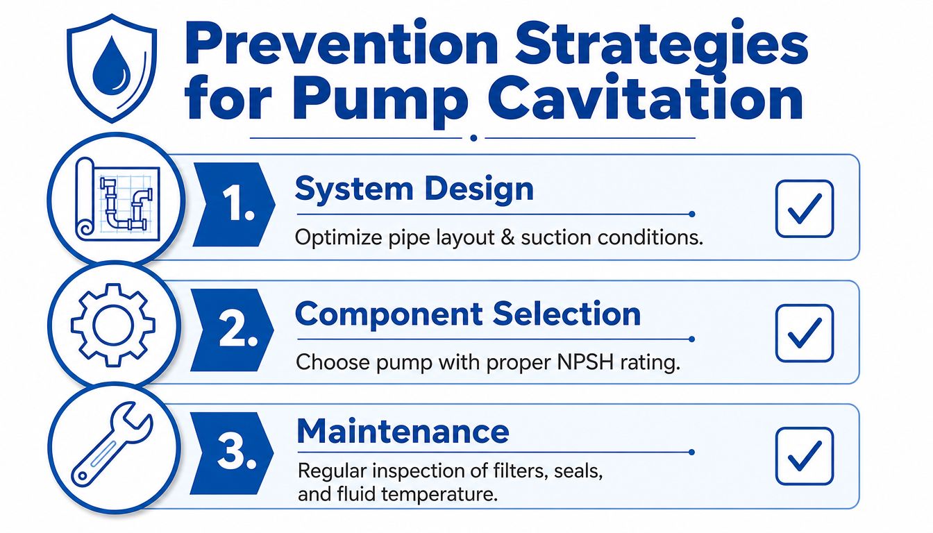
Cavitation prevention begins before installation, but existing systems can often be improved without replacing the complete pump. The strongest approach combines a favourable suction layout, correctly selected components and maintenance that protects the original design margin.
Design the inlet for low loss
Place the pump close to the reservoir and as low as practical, while maintaining safe access and suitable mounting. Keep suction runs short, use generous internal diameter and avoid unnecessary bends, reducers and valves. The objective is simple, preserve pressure at the pump inlet instead of spending it on avoidable friction.
Select suction filtration for the required cleanliness level, but don't treat a filter's micron rating as the only specification. Pressure drop, flow capacity, service access and contamination loading all matter. A filter that is technically fine when clean can become a serious restriction when neglected.
Choose components around the duty
Select a pump whose NPSHr suits the actual installation, not just the nominal flow rate. Check the full operating envelope, including hot fluid, variable speed, start-up and low-flow conditions. Higher-viscosity fluids increase suction losses, while higher-vapour-pressure fluids reduce the pressure margin.
The suction hose must resist collapse under vacuum and remain compatible with the fluid, temperature and movement of the equipment. MA Hydraulics' suction hose range provides a relevant reference when reviewing hose construction and application requirements.
Maintain the conditions you designed
A practical maintenance routine should include strainer inspection, hose and seal checks, reservoir-level verification and fluid-temperature monitoring. Record vibration and noise when the pump is healthy, then compare later readings against that baseline. This makes gradual deterioration easier to identify.
For an existing installation, retrofit options may include replacing a restrictive hose, removing unnecessary bends, relocating a filter, opening or resizing the suction path, lowering the pump relative to the reservoir or reducing operating speed where the duty permits. Fit a larger component only after checking the entire flow path, because one remaining restriction can continue to control the inlet pressure.
The most effective prevention work connects the calculation to the physical installation. A healthy NPSH margin on a drawing won't protect a pump if the installed hose is smaller, the filter is blocked or the reservoir level is lower than assumed.
Real-World Examples and Case Studies
Cavitation is often described as a pump fault because the impeller or casing shows the damage. That description hides the system conditions that created it. The following application patterns show why diagnosis must begin at the inlet.
Agricultural machinery
A tractor hydraulic pump can become noisy during cold starts when the oil is more viscous and a marginal suction arrangement develops higher losses. The useful diagnostic sequence is to compare the cold and warmed operating conditions, inspect the suction strainer and check the hose for collapse or restrictive bends. Improving the suction path and confirming the fluid condition addresses the mechanism rather than repeatedly changing the pump.
Industrial press equipment
A manufacturing press with a long suction hose and a contaminated filter may run acceptably after servicing, then develop the same symptoms as contamination builds again. The recurring failure pattern points towards restriction management, not necessarily poor pump quality. Measuring suction pressure before and after the filtration arrangement helps identify where the available margin is being lost.
Mobile plant
An excavator or other mobile machine can suffer chronic cavitation when the pump is mounted too high relative to the reservoir or when the tank and suction connection don't support the required inlet condition. Check static height, hose routing, tank level and operating temperature under the actual duty. The correction may involve mounting, plumbing or component selection rather than a different replacement pump.
These examples also show why technical communication matters. Maintenance teams need clear records of symptoms, measurements and corrective actions, while manufacturers need to explain system requirements plainly. For broader context on the communication challenges manufacturers face, see this guide from Machine Marketing.
When to Seek Professional Help and Contact MA Hydraulics
Basic checks are appropriate when a pump first becomes noisy, but stop treating the problem as routine troubleshooting when the symptoms persist after cleaning the strainer, opening valves, checking fluid level and inspecting the suction hose. Continued cavitation can damage the impeller, seals, bearings and casing, so running the equipment until the next planned shutdown may increase the repair scope.
Professional support is particularly useful when the system has several pumps, variable-speed operation, hot fluid, long suction lines or a duty that changes significantly during production. A proper review should examine the pump curve, NPSHr, NPSHa, fluid properties, static height, pipe and hose losses, valve arrangement and the operating point at which the noise begins.
Information to prepare before calling
A supplier or hydraulic engineer can work more efficiently if you provide:
- Pump make, model and displacement or capacity.
- Fluid type, viscosity and operating temperature.
- Reservoir level and pump mounting height.
- Suction hose internal diameter, length and routing.
- Filter and strainer details, including service history.
- Suction and discharge pressure readings.
- Flow requirement, pump speed and the conditions that trigger the noise.
- Photographs of the pump, hose connections, valves and reservoir arrangement.
MA Hydraulics Ltd supplies hydraulic components and bespoke power solutions for mobile and industrial applications. Its product support covers gear pumps, gear motors, flow dividers, valves, filters, gearboxes, clutches, bellhousings, couplings and manifolds, alongside Hydronit mini power packs and in-house bespoke industrial power packs up to 11 kW, as described in the company information provided for this article.
The right intervention may be a suction hose change, filter review, valve correction, pump selection exercise or a wider power-pack design review. The important point is to identify the inlet condition that is reducing the margin, then specify components around the actual duty.
Phone 01724 279508 today for advice on pump cavitation, suction-side restrictions and hydraulic component selection, or send MA Hydraulics a message through the contact page. For help reviewing an existing installation or building a bespoke hydraulic power solution, visit MA Hydraulics Ltd and speak with the team about the measured operating conditions.
