
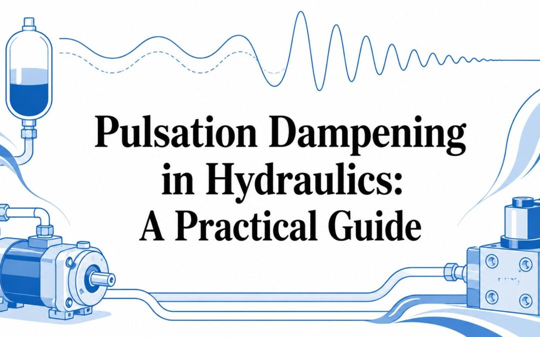
The operator feels it before the fault code appears. A telehandler's steering wheel starts to buzz as engine speed rises, the hydraulic hoses chatter against their clamps, and the pressure gauge needle refuses to settle. On a factory floor, a press may bang on every stroke while the pump whine climbs with each change in demand.
Those symptoms point to more than an irritating noise. Pressure pulsation can drive vibration, fatigue and premature component wear, while making faults harder to diagnose. For a maintenance manager, the consequences are familiar: unplanned downtime, replacement hoses and valves, operator complaints, and a machine that never feels properly under control.
Pulsation dampening can help, but it isn't a universal cure. The useful question is not which damper to buy. It's where the pressure fluctuation originates, which frequency is causing the trouble, and whether the better first intervention is a dampener, revised hose routing, a different valve response or proper measurement. For wider background on reducing hydraulic noise, see these hydraulic noise reduction techniques.
Why Pulsation Matters on Real Hydraulic Machines
A machine rarely announces pulsation as a neat engineering measurement. It announces it through feel and sound. On a mobile machine, the operator may notice a trembling steering wheel, a lift function that moves in small surges, or a rising whine as pump speed increases. In a workshop, the engineer may find a return hose flicking against a bracket, a gauge needle oscillating rapidly, or a fitting that repeatedly loosens despite being correctly tightened.
These are useful clues because hydraulic pressure doesn't always remain steady between pump discharge and actuator movement. A pump, valve or load change can introduce a repeating fluctuation into the fluid column. The pipework, hose assemblies and machine frame then transmit that energy, sometimes amplifying it rather than absorbing it.
Practical rule: Treat a new vibration or rhythmic noise as an early warning, not as a cosmetic defect.
The commercial effect is straightforward. A hose that flexes continuously can fail earlier than expected. A valve subjected to repeated pressure spikes can become difficult to control. A sensor may provide an unstable signal, leading a technician to replace the wrong component. On production equipment, a small hydraulic disturbance can interrupt a repeatable cycle and create more inspection or adjustment work.
UK engineering research has treated this as a formal systems problem for more than a decade. The University of Bath reported work published in September 2012 on active control of pressure pulsation in a switched inertance hydraulic system, placing UK-led pulsation control in a modern engineering context rather than treating it as a niche maintenance concern. The University of Bath research record is particularly relevant to engineers who need to understand why pressure ripple must be considered alongside noise, vibration and fatigue.
The first job on site is therefore tracing the symptom. Listen at different engine or motor speeds, check whether the problem follows pump delivery or valve operation, and inspect how hoses and rigid pipework are supported. A dampener may be the right answer, but only after the hydraulic source and transmission path are understood.
What Pulsation Dampening Means
A pressure pulsation is a repeated fluctuation around the circuit's average working pressure. It differs from water hammer, which is a sharp transient caused by a rapid change in flow. The distinction matters on site because the remedies are different. A multi-cylinder engine provides a useful comparison: overall flow continues, while individual pulses remain visible in the pressure waveform.
In a hydraulic circuit, pulsation can originate from pump displacement events, valve switching, load changes, or interaction between the fluid column and the surrounding structure. Pulsation dampening reduces that oscillation to a level the machine can tolerate. Supplier literature may also refer to ripple, surge, or water hammer, but those terms describe related disturbances rather than identical conditions.
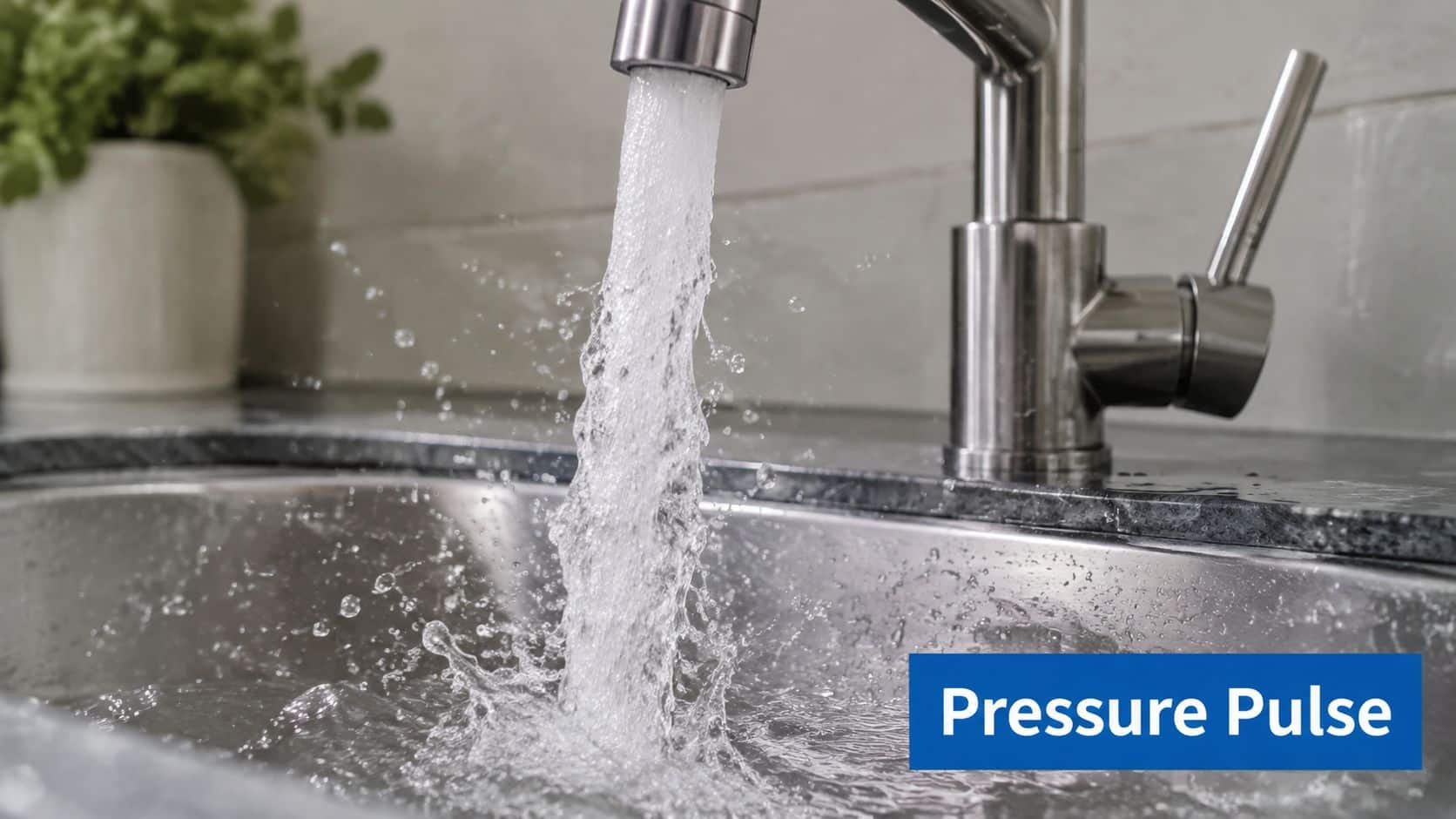
Two measurements govern the control problem:
- Amplitude is the pressure movement above and below the average. It may be specified in bar or as peak-to-peak pressure.
- Frequency is how often the fluctuation occurs, measured in hertz. Pump speed, displacement events, and the number of pistons or chambers all affect it.
A gas-charged dampener uses a compressible nitrogen volume to absorb part of each pressure event. Rising hydraulic pressure compresses the gas. As pressure falls, the stored energy is released, helping smooth the waveform. The pump still produces its displacement events. The dampener limits how much of that energy reaches pipework, valves, and the actuator.
Size alone does not guarantee a result. Gas condition, connection arrangement, and the device's response band must suit the disturbance. A capacitance-type dampener has been reported with 5–40 dB attenuation across roughly 20–3000 Hz, showing why performance depends on frequency. The TPD dampener datasheet.pdf) provides the cited attenuation range.
Dampening remains one part of vibration control. If the problem is caused by poor hose routing, an unsuitable valve, or a resonance elsewhere in the circuit, changing the dampener will not correct the source. Confirm the frequency and pressure behaviour before choosing the component.
How Pulsation Damages Hydraulic Systems
Pulsation is a repetitive pressure fluctuation around a mean working pressure. It differs from a sharp transient such as water hammer, but repeated peaks can still impose significant mechanical and acoustic loads on a hydraulic circuit.
The first common failure route is mechanical fatigue. Hoses, tube bends, clamps and fittings may withstand the nominal working pressure, yet deteriorate when pressure peaks repeat while the assembly is moving, rubbing or held under strain. A hose can look acceptable during a static inspection and still be close to failure if each pump cycle excites the same section.
Rigid pipework is vulnerable for similar reasons. An unsupported run can resonate and transfer energy into brackets, manifolds and machine panels. If a short flexible connection is missing, pump vibration can pass directly into the rigid structure, increasing noise and loosening fittings.
What engineers usually find first
Bearings in pumps and motors may suffer when pressure excitation couples with mechanical resonance. Rapid pressure changes can create harsh local conditions at valve seats and spool lands, while unstable pressure makes proportional control harder to tune. The resulting fault history may include several small symptoms rather than one obvious failure point.
Noise is both a warning sign and a load on the surrounding machine. UK technical material reports laboratory testing in which a pulsation damper reduced structural noise by more than 95%, with setting-in dampening exceeding 25 dB and typical sound-level reductions of approximately 10–20 dBA. These are laboratory results in the UK technical pulsation damper document.pdf), not figures to copy into a site guarantee. They do show that acoustic control affects equipment condition and working conditions, not just operator comfort.
A separate UK guide describes a hydraulic power pack transmitting vibration through a steel floor and producing 88 dB noise. After properly specified anti-vibration measures were applied, the remaining reduction was no longer measurable against background factory noise, as explained in this UK pulsation dampener guide.
| Component affected | Symptom or failure mode | Typical consequence |
|---|---|---|
| Hose assemblies | Chatter, rubbing, fatigue at bends or fittings | Leakage, blow-off or burst line |
| Rigid pipework | Resonance and transmitted vibration | Cracked supports, loosened fittings and structural noise |
| Pumps and motors | Bearing excitation or unstable discharge | Premature overhaul and difficult fault diagnosis |
| Valves | Harsh switching, seat damage or unstable control | Poor actuator movement and repeatability |
| Gauges and sensors | Unsettled readings or signal fluctuation | Incorrect adjustment or replacement of healthy components |
| Machine structure | Airborne and structure-borne noise | Operator complaints, disturbed surroundings and maintenance attention |
The correct response depends on the dominant problem: pressure amplitude, frequency, structural transmission, or a separate hydraulic fault. A dampener can reduce pressure ripple, but it will not correct poor hose routing, an unsuitable valve or resonance elsewhere in the circuit. Select it as part of a wider vibration-control strategy, supported by pressure and frequency checks before a noisy component fails.
Comparing the Main Pulsation Control Methods
No single device suits every circuit. A fixed-displacement pump, a load-sensing swashplate pump and a reciprocating diaphragm pump create different disturbances, while a mobile machine has different space and vibration constraints from a fixed industrial press.
The practical options
Bladder and piston dampeners use a gas volume to absorb pressure fluctuation. They're useful where the pressure source is known and a passive device can be tuned to the operating conditions. Their compactness can suit mobile equipment, but the wrong pre-charge, insufficient effective volume or poor frequency match can leave the main problem untouched.
Hydro-pneumatic accumulators provide a gas cushion that can smooth pump ripple as well as perform other hydraulic duties. UK technical guidance shows that specification is based on pressure, volume and frequency handling rather than pump size alone. For example, a UK-supplied HYDAC silencer is rated from 0.5–5.5 L and up to 330 bar, while a broader UK supplier range is listed from 1–32 L and 330–1,000 bar. These figures can be checked in the HYDAC pulsation damper technical material and the HYDAC accumulator range. The limitation is that a general-purpose accumulator may not provide the same response as a purpose-designed pulsation unit.
Damping lines and absorber hoses introduce compliance into the fluid path and can reduce transmission into rigid pipework. They're attractive where installation space is limited, but they need correct pressure, temperature, bend-radius and support checks. They won't cure a pump that is badly worn or a valve that is switching too aggressively.
In-line filters with damping chambers can combine contamination control with some hydraulic smoothing. That may suit a circuit where the filter already needs replacing, but the damping effect shouldn't be assumed from the filter body alone. Pressure drop, element condition and flow direction remain important.
Valve selection can outperform extra hardware when the disturbance begins at switching. Proportional valves, soft-shift directional valves and correctly controlled ramp rates reduce the abrupt change that creates a surge. They cost more in control complexity and won't correct a pump-generated pulse that exists throughout the delivery line.
Piping and hose routing changes alter how vibration reaches the machine. Flexible hose at the right connection, better support and a change in the run can shift or reduce structural resonance. The trade-off is installation labour and space, particularly on compact mobile equipment.
| Method | How it works | Best for | Typical pulse frequency | Relative cost | Main limitation |
|---|---|---|---|---|---|
| Bladder or piston dampener | Compresses gas to absorb pressure variation | Known pump ripple and defined operating duty | Must be matched to measured or estimated frequency | Moderate | Needs correct pre-charge and volume |
| Hydro-pneumatic accumulator | Uses gas compressibility to smooth pressure and flow | Ripple control plus wider accumulator functions | Dependent on system dynamics and tuning | Moderate | General units may not suit every band |
| Damping line or absorber hose | Adds compliance between source and structure | Hose fatigue and transmitted vibration | Dependent on hose and line arrangement | Low to moderate | Limited by pressure, temperature and durability |
| Filter with damping chamber | Combines filtration with fluid-volume damping | Systems already requiring filtration | Application-dependent | Moderate | Damping performance isn’t automatic |
| Proportional or soft-shift valve | Controls the rate of pressure and flow change | Switching surge and harsh actuator response | Linked to valve response and control settings | Moderate to high | Won’t remove pump-generated ripple |
| Routing and support changes | Interrupts vibration transmission or shifts resonance | Structural noise and hose movement | Dependent on pipework geometry | Low to moderate | Doesn’t absorb pressure at the source |
Selection rule: Measure or identify the source first. Add a dampener when the pressure waveform is the problem, and change the fluid path or valve response when transmission or switching creates the dominant disturbance.
Sizing Dampeners and Accumulators for the Job
Sizing from pump displacement alone is a common mistake. A workable specification starts with system pressure, flow, pulse amplitude, frequency and duty cycle. The source may be a fixed-displacement gear pump, a piston pump, a diaphragm pump or a variable-displacement unit changing output in response to load.
Begin by capturing a pressure trace at the point where the problem is visible. A suitable pressure transducer and recording system can show whether the issue is a repeating pulse, a short surge, valve switching or a broader resonance. If measurement isn't available, estimate the disturbance from the known pump arrangement, but treat that estimate as a starting point rather than a final size.
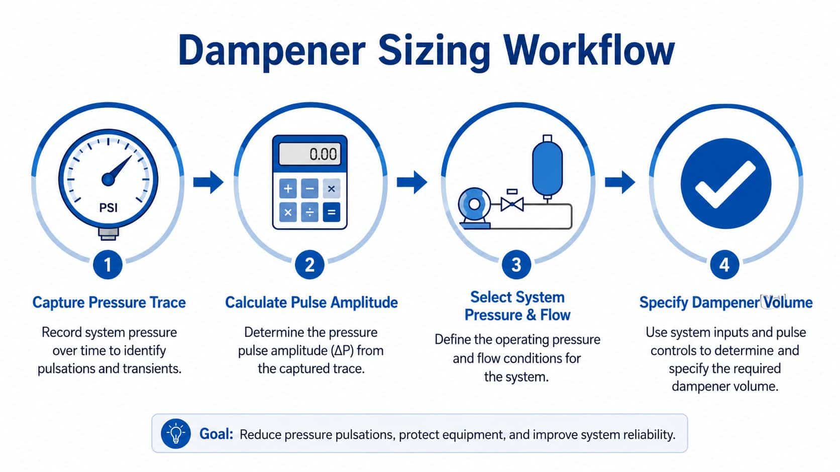
A workable sizing sequence
- Record minimum and maximum pressure. Identify the operating range, relief setting and any short transient that the damper must tolerate.
- Establish the frequency. Relate the pressure trace to pump speed and displacement events. A unit that works at one speed may be less effective when the engine or motor changes speed.
- Select the effective volume. Gas volume, fluid volume and the pressure range determine how much energy the unit can absorb. Manufacturer data should be checked at the actual pressure and temperature, not just the catalogue headline.
- Set the gas condition. Bladder and piston units normally require nitrogen pre-charge selected in relation to minimum working pressure. Too much pre-charge reduces fluid entry and can make the unit ineffective. Too little can allow excessive movement, heat or internal damage.
Mounting distance matters because the line between the source and damper has its own fluid stiffness and resonance behaviour. Line length, hose construction and the fluid bulk modulus all change the response. Place the damper close to the pump or the component being protected, then verify the result with another pressure trace.
For a mobile loader circuit, the practical workflow is to capture the pressure event during steering and lift operation, identify whether it follows engine speed or valve switching, and select a compact unit rated for the maximum circuit pressure and expected temperature. For a fixed industrial press, record the trace over the complete cycle, because the pulse may only appear during rapid approach, forming or return. The two machines may have similar nominal flow, yet require different volume, connection location and control methods.
Use hydraulic accumulator sizing guidance alongside the manufacturer's performance curves. Don't approve a component until the supplier has confirmed pressure rating, fluid compatibility, effective volume, connection size, temperature range and the intended pre-charge procedure.
Installation and Maintenance Best Practice
A correctly sized damper can still fail to deliver if it's installed in the wrong place. Mount it close to the pulse source or close to the component that needs protection, depending on the measured transmission path. A damper fitted downstream of a troublesome valve may do little for the upstream pipework that's already vibrating.
Use a flexible hose at the connection where vibration would otherwise enter rigid pipework. Secure the unit independently and don't use its body as a structural bracket. Keep it away from excessive heat, allow access for pre-charge checks, and provide a gauge or test point where the pressure trace can be verified.
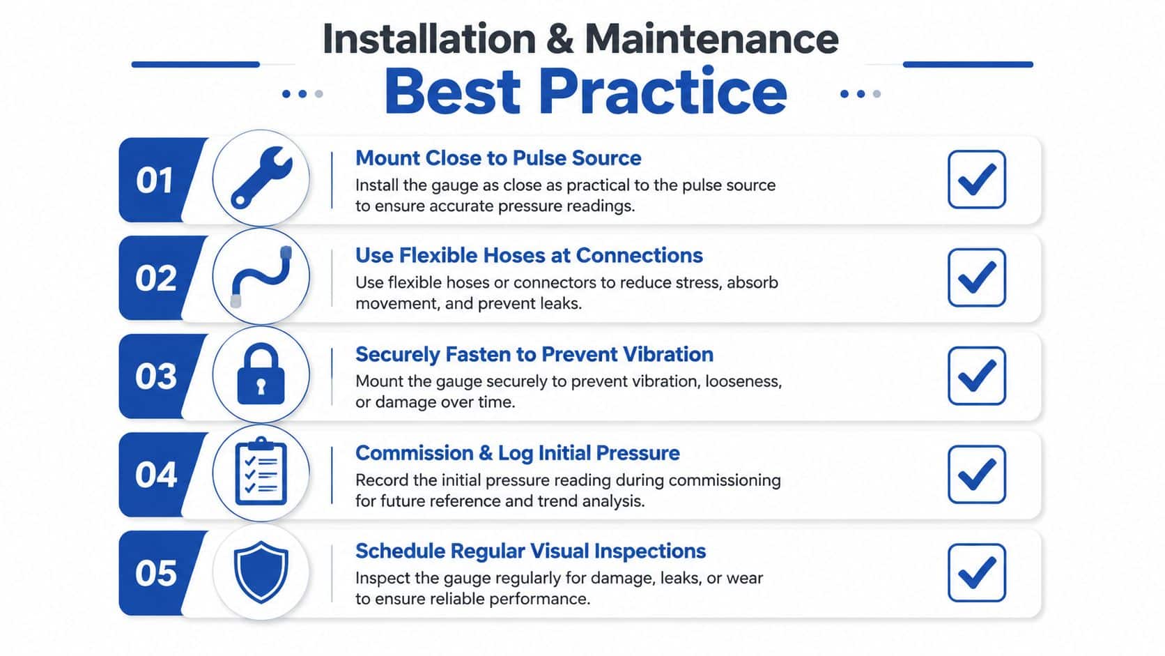
Commissioning should create a baseline
With the hydraulic system depressurised and isolated, check the nitrogen pre-charge using the correct charging equipment. Then ramp the machine slowly towards normal pressure while checking for leaks, abnormal movement and unexpected temperature rise. Capture the pressure trace before and after installation where possible, and record the operating speed, pressure, flow condition and valve state.
The baseline is valuable because a later change in amplitude can reveal gas loss, bladder deterioration, internal leakage or a new pump fault. A unit that initially works well but gradually loses its effect shouldn't be adjusted blindly. Check the pre-charge and inspect the rest of the circuit first.
Maintenance should be planned around the duty and manufacturer's instructions. Include nitrogen pre-charge verification in the site routine, inspect the bladder during overhaul, and check hose condition, clamps, supports and fitting torque. The accumulator charging procedure should be followed with the system made safe, the correct gas used, and the charging rate controlled.
Common site errors include:
- Skipping the post-refill check. Any change to gas charge alters the operating response.
- Mounting after the protected component. The damper can't remove energy that has already passed through a vibrating valve or pipe run.
- Ignoring flexible connections. A rigid connection can transfer vibration directly into the machine frame.
- Poor access. If technicians can't reach the test point safely, pre-charge checks will be delayed.
- Using the unit as a support. The pipework should be independently supported so the damper isn't carrying mechanical load.
A maintenance record should include the original pressure trace and the conditions under which it was captured. Without that context, later readings are difficult to compare.
When Dampening Is Not the Answer
A machine can become noisy after a pump change, a hose replacement or a valve setting adjustment. Adding a damper may reduce the symptom, yet noise and vibration alone do not prove that pump pulsation is the root cause. Suction-side air ingress, pump wear, coupling misalignment, unstable valve response and a long unsupported pipe run can produce similar behaviour.
Hose routing deserves early attention. Experimental work has shown that changing hydraulic hose configuration can reduce noise by approximately 5 dB(A) in some power units. The result supports a practical point: the fluid path can amplify or suppress a disturbance before a specialist component is added. Check the route, bend radius, supports and contact points before spending money on a larger or additional damper.
Diagnose before buying
Pressure transducers show the hydraulic waveform, while accelerometers help identify where vibration enters the structure. Frequency-domain analysis can separate pump-related pulses from resonance in a frame, bracket or pipe span. A short measurement exercise may cost less than repeated component changes, particularly when a new damper would leave the original fault untouched.
Start with the source and the affected component, then compare readings at intermediate points where access allows. A change in amplitude or frequency across the circuit helps distinguish a pressure disturbance from structural amplification.
Hoses need a suitable bend radius, independent support and enough freedom to absorb movement without rubbing. Flexible mounts and isolators can alter the structural response. A revised valve ramp or soft-shift setting may reduce a switching event more effectively than a damper. Check pressure, temperature, movement, abrasion and inspection access when making the change.
| Symptom | Likely root cause | Best response |
|---|---|---|
| Vibration follows engine speed | Pump-generated pressure ripple or mechanical excitation | Capture pressure and vibration traces, then match control to frequency |
| Noise appears during valve switching | Abrupt flow or pressure change | Review valve type, ramp settings and control response |
| Hose moves at one machine speed | Structural resonance or poor support | Improve routing, clamping and isolation, then verify the operating band |
| Unstable gauge reading | True pulsation, sensor limitation or poor mounting | Use a suitable transducer and compare readings at several points |
| Pump is noisy with suction bubbles | Air ingress or inadequate inlet condition | Inspect suction hose, connections, reservoir level and inlet restrictions |
| Vibration remains after damper installation | Wrong location, pre-charge or root cause | Check installation and charge, then return to measurement |
UK guidance describes dampers as a way to limit fluid-borne vibration travelling into pipework and structures. Structural vibration can still originate in a bracket, hose route, valve event or machine resonance rather than in a pressure pulse.
Pulsation dampening belongs inside a wider vibration-control plan. Use measurements to decide whether the first change should be a damper, hose redesign, valve adjustment or fault repair. The right answer may be a combination, but the diagnosis should come before the purchase.
Pulsation Dampening Checklist and Next Steps
A noisy machine becomes manageable when the investigation follows a repeatable sequence. Start with the operator's description, then reproduce the symptom under controlled conditions. Record engine or motor speed, pressure, flow demand, valve position and the point at which the vibration or noise appears.
The buying and specification workflow
- Confirm the noise source. Listen at the pump, valve, hose, manifold and machine structure. Note whether the sound changes with speed or only with a particular function.
- Capture the baseline pressure trace. Measure at the source and, where practical, near the affected component. Record minimum, maximum and repeating waveform behaviour.
- Identify the pulse rate. Relate the frequency to pump speed and displacement events. Don't select a unit solely from nominal pump flow.
- Choose the control method. Decide whether the evidence points to a bladder or piston damper, accumulator, damping line, valve adjustment, routing change or a combination.
- Specify the component. Confirm maximum pressure, effective volume, fluid and seal compatibility, temperature, connection arrangement, installation orientation and gas pre-charge.
- Install, commission and log. Fit close to the source or protected component, use suitable flexible connections, verify pre-charge safely, and compare the post-installation trace with the baseline.
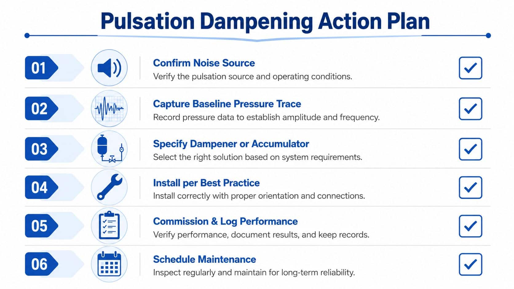
Before placing an order, give the supplier more than the pump model. Provide the pressure range, flow range, fluid, temperature, pump type, operating speed, connection size, available space and the measured symptom. Ask for performance data at the relevant pressure and frequency, not a generic statement that the product reduces pulsation.
On site, keep a record of hose routing, clamp locations, pre-charge, pressure readings and the machine condition during commissioning. Use manufacturer data sheets and applicable UK and European requirements for pressure equipment, installation and safe maintenance. The record will help distinguish normal variation from a developing fault during future servicing.
A UK technical brochure identifies AMS diaphragm accumulators as being used as shock absorbers and pulsation dampeners in industrial, machine tool and agriculture sectors, with UK contact and manufacturing details included in the document. That UK accumulator brochure reflects the range of applications where this approach is used in practice.
MA Hydraulics Ltd can help specify hydraulic accumulators, dampeners, valves, hoses and related components for mobile and industrial systems, including bespoke power-pack requirements. Visit MA Hydraulics Ltd with your pressure trace, duty details or replacement requirement, and speak to the team about the most suitable route for controlling pulsation.
Call MA Hydraulics Ltd on 01724 279508 today for practical help selecting and sizing hydraulic components for pulsation control, or send us a message with your application details. The team can help you assess whether a dampener, accumulator, hose arrangement or wider hydraulic change is the right solution for your machine.
