
Most hydraulic systems in the UK are working far harder than they need to. Average hydraulic system efficiency is estimated at only 22%, which means nearly 78% of input energy is lost through heat, friction, and pressure drops according to Advanced Science Research. That figure changes how performance optimization should be viewed. It isn't a fine-tuning exercise for perfectionists. It's a practical way to cut waste, stabilise machine behaviour, and protect component life.
In day-to-day engineering work, poor performance rarely shows up as a single dramatic fault. It shows up as hot oil, slow cycles, noisy pumps, drifting actuator speeds, awkward valve response, and a maintenance team replacing parts before anyone has fixed the cause. Good performance optimization starts by treating the system as a whole, then proving each improvement with measured data.
The Hidden Cost of Inefficient Hydraulics
A hydraulic pack can pass a function test and still waste a damaging amount of power every shift. In UK plants, that usually shows up as rising oil temperature, unstable cycle times, nuisance faults, and a maintenance budget that grows faster than output. As noted earlier, average hydraulic efficiency is far lower than many teams assume, so poor performance is rarely a minor housekeeping issue.
What matters on site is where those losses end up. They do not disappear. They turn into heat, pressure drop, noise, and unnecessary load on the motor or engine. Over time, that changes how the whole machine behaves and what it costs to keep it available.
Where the costs accumulate
Energy is only the first line on the bill. In practice, inefficient hydraulics create a chain of secondary costs that often outweigh the electricity or fuel loss.
- Higher thermal stress: hotter oil shortens fluid life, shifts viscosity, and makes response less consistent across a shift.
- Shorter component life: pumps, valve spools, seals, hoses, and motors spend more time operating outside their preferred range.
- More misdiagnosis: pressure loss, internal leakage, aeration, and poor valve settings can produce similar symptoms, so teams replace serviceable parts and leave the root cause in place.
- Greater production risk: a system that is slow, erratic, or temperature-sensitive is harder to plan around and more likely to stop the machine at the worst point in the duty cycle.
I have seen this repeatedly on older power packs. A unit described as "temperamental" often turns out to be oversized, heavily throttled, and running unnecessarily hot. The machine still works, but every hour of operation carries avoidable cost.
That is why performance optimization needs to sit alongside reliability planning, spares strategy, and total cost of ownership in hydraulics. Purchase price rarely tells the full story. A cheaper pump or a quick valve substitution can look sensible at order stage, then cost far more in energy, fluid changes, call-outs, and lost production over its service life.
The same principle is well understood in other asset-heavy sectors. The Wuxi Winteam Technology fleet guide makes the point clearly for vehicles and engines. Operators who track performance as a cost system, rather than a repair history, make better decisions about maintenance timing and asset replacement. Hydraulic equipment is no different.
Why generic advice misses the mark
General advice such as "check for leaks" or "fit more efficient components" is not enough for an engineer trying to justify downtime, parts spend, or a retrofit budget. The useful questions are more specific. Is the pump sized for the actual duty, not the worst-case assumption from the original design? Is excess flow being dumped across a relief or burned off through throttling? Is heat being generated by contamination-related wear, poor line sizing, or a valve strategy that no longer matches production demand?
Those details decide whether an intervention pays back in months or never pays back at all.
At MA Hydraulics, the best results usually come from right-sizing and measured correction, not from replacing parts on instinct. A system on repetitive factory duty needs a different optimisation plan from a mobile machine facing variable loads and intermittent peak demand. UK engineers and MRO teams need that distinction, because the commercial case depends on actual operating hours, energy tariffs, downtime cost, and how critical the asset is to production.
Establishing Your Performance Baseline
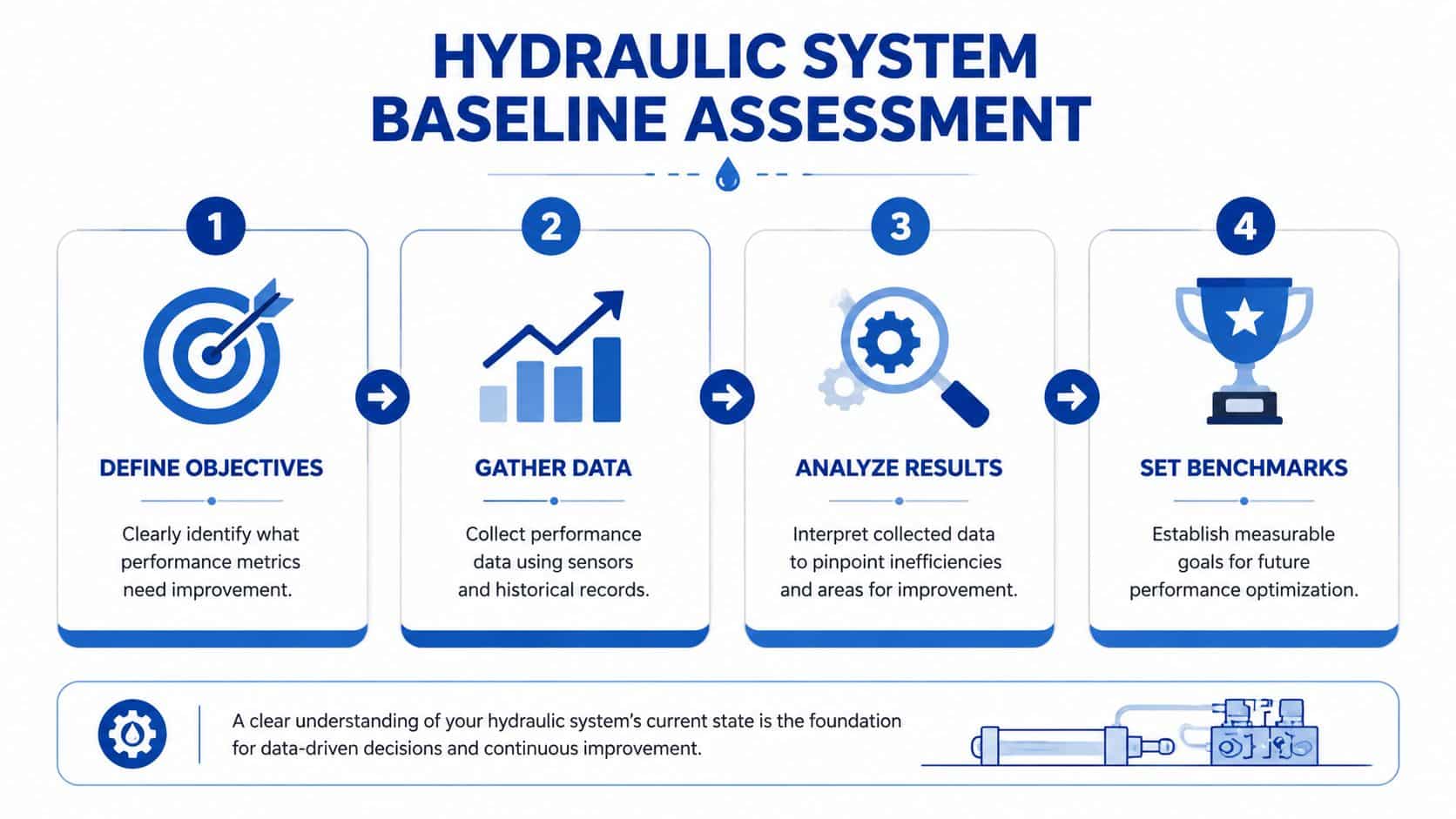
If the baseline is weak, every conclusion after it is shaky. Before changing pumps, valves, settings, or pipework, record how the system behaves now. The fastest way to waste time on a hydraulic project is to improve the wrong thing.
In UK practice, a structured approach starts with baseline operating data. A step-by-step performance optimization methodology begins with recording flow, pressure, and temperature, followed by sensitivity analysis in which inflow and hydraulic roughness parameters are adjusted by approximately 20% to identify uncertainty sources, according to UK government hydraulic modelling best practice.
Start with the operating condition that matters
A baseline taken at idle tells you very little about a machine that struggles under load. Record values during the duty that causes complaints. For most systems that means noting:
- Pressure in bar: at pump outlet, across key valves, and at the actuator when loaded.
- Flow in L/min: actual delivered flow, not just catalogue pump displacement.
- Temperature in °C: tank, pump case area where relevant, and return line.
- Power in kW: motor draw or overall pack demand during real operating conditions.
If the machine has different modes, log each one separately. Fast approach, loaded work stroke, hold pressure, and return stroke can all reveal different losses.
What to inspect before you connect instruments
Instrumentation matters, but first use your eyes and ears. A quick physical inspection often explains why measured data looks wrong.
- Check for external leakage. Even a minor recurring leak changes contamination risk and system stability.
- Inspect hoses and pipe routing. Poor routing can trap air, create vibration, and add avoidable pressure loss.
- Look for heat clues. Darkened paint near components, cooked sleeves, and hardened seals usually point to a chronic issue rather than a recent one.
- Listen at start-up and under load. Cavitation, aeration, and relief valve chatter have distinct sound signatures.
A useful cross-industry habit is to define what “good” looks like before collecting data. The Wuxi Winteam Technology fleet guide does this well from an equipment monitoring perspective. The hydraulic equivalent is deciding in advance which metrics matter for the machine. Cycle consistency, loaded speed, oil temperature stability, and pressure recovery are usually more useful than taking a long list of readings with no decision attached to them.
Measure enough to compare, not just enough to observe
A common mistake is taking single spot readings. That confirms the machine is alive, but it doesn't establish performance.
Use a short baseline sheet or logger that captures:
| Measurement point | What to record | Why it matters |
|---|---|---|
| Pump outlet | Pressure, temperature trend | Shows supply conditions and heat build-up |
| Across control valve | Pressure difference | Highlights throttling losses |
| Actuator line | Pressure and speed response | Confirms useful work at the point of action |
| Tank or return | Temperature and return condition | Indicates overall thermal health |
Practical rule: if you can't repeat the measurement at the same operating point next week, it isn't a reliable baseline.
Where possible, compare cold start behaviour with normal running temperature. Many systems look acceptable when the oil is cool, then drift badly once viscosity changes. That's where performance benchmarking for hydraulic systems becomes valuable. It turns scattered observations into a repeatable reference.
Calculate efficiency where it counts
For pump assessment, use actual flow rather than assumptions. Volumetric efficiency is determined by dividing the actual flow output by the theoretical flow output at the pump's operating pressure, as explained in Brennan's guidance on hydraulic efficiencies. That one calculation is often more revealing than a general discussion about whether a pump “feels weak”.
A strong baseline doesn't solve the problem by itself. It tells you where to act first. That usually leads straight to component matching.
Strategic Component Selection and Matching
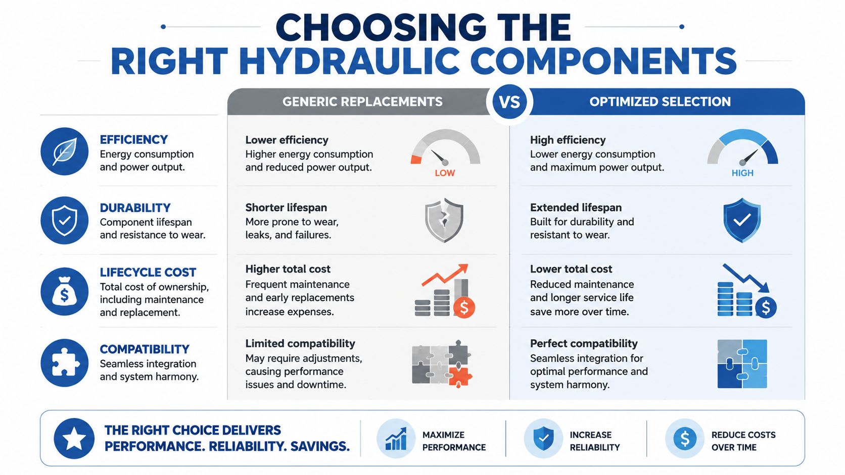
Replacing a failed part with the same model is sometimes correct. It is not always intelligent. If the original circuit was oversized, over-throttled, or poorly matched to the duty cycle, like-for-like replacement restores the same inefficiency.
The most important question isn't “what fits the manifold?” It's “what flow, pressure, and control behaviour does the application really need across its full duty cycle?” That's where performance optimization moves from maintenance into engineering.
Fixed displacement versus variable displacement
This is one of the clearest examples of design choice affecting energy use. Selecting a variable displacement pump instead of a fixed displacement pump can reduce energy consumption by adjusting flow to match system demand and eliminating the losses associated with throttling excess flow, as outlined in this technical explanation of pump selection.
That doesn't mean every system should be converted. A simple fixed displacement arrangement can still be the right answer when:
- duty is repetitive and predictable
- cost and simplicity matter more than control flexibility
- the machine spends little time idling under light demand
- maintenance support in the field must stay straightforward
A variable displacement option makes more sense when load and speed demand move around significantly during normal use.
Right-sizing beats over-sizing
Oversized components often get chosen for safety margin. On paper, that feels prudent. In service, it often creates avoidable throttling, excess heat, and poor controllability at low demand.
Consider the usual matching problems:
- Pump too large: excess flow is dumped or throttled away.
- Valve too small for real flow: pressure drop rises and heat follows.
- Actuator speed set by restriction rather than correct flow source: response becomes inconsistent as temperature changes.
- Motor and pump combination picked for peak demand only: system spends most of its life operating inefficiently away from its sweet spot.
What to look for on datasheets
A good datasheet doesn't choose the part for you. It gives you the limits and operating window. Engineers still need to match those limits to the machine.
Check these points before selecting a replacement or redesigning a circuit:
| Component | What to match | Common mistake |
|---|---|---|
| Gear pump | Displacement, pressure range, direction, speed range | Choosing only by mounting pattern |
| Valve | Nominal flow, pressure loss, spool type, control method | Ignoring pressure drop at working flow |
| Motor | Torque requirement, speed range, case drain needs | Matching speed but missing load behaviour |
| Power pack | Continuous duty, reservoir size, cooling requirement | Sizing only for peak output |
With brands such as Vivoil, Hydronit, and Luen, the practical issue isn't just availability. It's making sure the chosen pump group, valve size, and power unit specification suit the machine's real work profile, not an assumed one.
A good component match makes the system feel calm. Pressure stabilises faster, oil temperature behaves, and operators stop compensating for the machine.
Where design support is needed, MA Hydraulics Ltd can supply hydraulic components and bespoke power packs up to 11 kW, which is useful when the job calls for matching gear pumps, valves, manifolds, and compact power units around an actual duty requirement rather than a generic replacement.
Fluid Management and Contamination Control
Oil condition sits behind a large share of hydraulic reliability problems. In practice, many faults that look like pump, valve, or actuator failure start with viscosity drift, heat, water ingress, or particle contamination.
That makes fluid management part of performance optimization, not a separate housekeeping task.

Temperature and viscosity must stay together
A fluid can match the specification on paper and still be wrong for the machine's actual duty cycle. Cold starts in winter, high ambient temperatures, and long working periods all shift viscosity. Once the oil moves outside the range the pump and valves were selected around, starting torque rises, internal leakage changes, response becomes inconsistent, and heat builds faster.
Field work on UK industrial units shows the pattern clearly. Machines that run hot rarely suffer in one place only. Cycle consistency drops, seals harden sooner, and operators often compensate by increasing pressure or extending run time, which raises the cost further.
Published work on hydraulic control and system performance notes the value of keeping oil temperature under control and matching pump tolerances to the application, particularly in heavy-duty power packs, as discussed in this ScienceDirect study on hydraulic control and system performance. In day-to-day maintenance terms, the point is simple. Watch oil temperature and viscosity together, because one without the other gives an incomplete picture.
Cleanliness is a performance issue
Fine contamination wears components slowly enough to be missed during routine fault-finding. The machine may still run, but valve spools start sticking, leakage across clearances increases, and pump surfaces lose efficiency. By the time operation feels rough or unstable, the damage is already established.
For MRO teams, three checks usually give the best return:
- Filter to the most sensitive component: servo and proportional valves usually need much cleaner oil than basic on-off circuits.
- Sample from a live, representative point: a return line or dedicated test point gives a better view than a stagnant reservoir corner.
- Find the ingress route: repeated filter changes without fixing damaged breathers, poor seals, or bad transfer practice only slow the wear rate.
The same study also highlights the link between cleanliness control and pump life in heavy-duty power pack service. For UK engineers, ISO 4406 targets should be set against the actual components fitted and the cost of failure, not treated as a generic box-ticking exercise. That is where right-sizing and maintenance planning meet. A compact pack with tight-clearance valves needs a stricter cleanliness strategy than a low-duty system with tolerant components.
Cooling and filtration choices
Cooling and filtration faults are often built into the layout. I see this regularly on compact power units where the cooler was sized for nominal duty, not the actual working cycle, or where the only protection against contamination is a coarse suction strainer.
A sound arrangement usually includes:
- Return filtration to capture wear debris before it recirculates
- Proper breather protection to limit dirt and moisture ingress as the reservoir breathes
- Cooler capacity matched to real heat load rather than catalogue flow alone
- Access for sampling and maintenance so condition checks happen before failure
If the oil is dirty, aerated, waterlogged, or too hot, careful valve adjustment will not recover stable performance.
Fluid analysis, cleanliness control, and cooling reviews also support predictive maintenance. They give trend data that helps teams plan filter changes, investigate abnormal wear early, and justify spend with a clearer ROI. That matters in UK service environments where downtime cost usually outweighs the price of oil, filters, or a better breather assembly.
Advanced Tuning for Precision and Efficiency
Small setting errors create large operating penalties. In service work across the UK, I regularly see capable hydraulic systems lose accuracy, run hotter than they should, and consume more power because final tuning was treated as a quick commissioning job instead of a measured engineering task.
Good tuning starts with the duty cycle, the load, and the response the machine needs. A press, test rig, or mobile attachment does not benefit from the same valve behaviour, pressure margin, or controller settings. Copying values from a similar machine is one of the fastest ways to build inconsistency into an otherwise sound system.
Relief valves and flow control
Relief pressure should cover the working load with a sensible safety margin. It should not act as a routine bypass for excess pump flow. If oil is crossing the relief valve during normal production, the system is converting electrical input into heat and noise instead of useful work.
Flow control needs the same discipline. Throttling can be a valid way to stabilise actuator speed, but it does not correct a poor pump and valve match. Where speed is controlled by heavy restriction across changing loads, response drifts as oil temperature rises and repeatability suffers.
A practical tuning sequence looks like this:
- Measure the pressure required at the actuator under load.
- Set the relief valve to suit that duty, with only the margin the application needs.
- Record pressure drop across the main control valve during the working stroke.
- Adjust flow to achieve target speed, then check temperature rise and cycle consistency.
- Repeat the test at normal operating temperature.
That process gives MRO teams something they can defend with data, not guesswork.
Proportional valve tuning and PID control
Proportional and servo-controlled systems reward careful setup. They also expose weak commissioning practice very quickly. Poor tuning usually shows up as sluggish response, hunting, overshoot, or a machine that behaves well unloaded but loses control once the work starts.
I prefer to tune from measured behaviour. Step response, settling time, steady-state error, and loaded versus unloaded performance tell you far more than whether the machine "feels better" after a parameter change. For UK plants trying to tie hydraulics into predictive maintenance, these values are worth recording as part of the baseline because drift over time often points to wear, stiction, internal leakage, or a change in duty.
| Symptom | Likely tuning issue | Typical result |
|---|---|---|
| Sluggish response | Gain too low or correction delayed | Longer cycle times and poor positional accuracy |
| Hunting or oscillation | Gain too high or damping too low | Heat, instability, and accelerated wear |
| Stable unloaded, poor under load | Controller not matched to real load variation | Inconsistent production performance |
Where energy use is under scrutiny, tuning work should also sit alongside a wider hydraulic energy consumption reduction strategy. Better control accuracy often reduces wasted motion, unnecessary pressure peaks, and operator intervention.
Don't tune around mechanical faults
Controller adjustments cannot compensate for poor pipe routing, trapped air, loose mountings, or actuator friction. They only mask the problem for a short period.
In the field, this matters more than many teams expect. A circuit with aeration or line compliance can produce symptoms that look like bad PID values, yet the controller is reacting to unstable hydraulic conditions. The result is wasted commissioning time and a machine that still will not hold tolerance once it heats up.
Check the physical system before changing software parameters:
- Pipework support and routing
- Signs of aeration or cavitation
- Cylinder and motor leakage under load
- Valve spool condition and hysteresis
- Sensor placement and signal stability
At MA Hydraulics, we have found that the best tuning results come after the mechanical and hydraulic basics have been verified under real operating conditions. That approach also supports the financial case for tuning work. Teams focused on cutting business energy costs usually find that stable settings, lower heat rejection, and fewer operator corrections produce savings that are easier to measure than headline efficiency claims alone.
Tune the hardware first. Then tune the control loop.
Driving Down Costs with Energy Saving Strategies
The old set-and-forget approach still turns up in hydraulic systems everywhere. Pump runs at full speed. Valve trims away the excess. Oil gets hot. Cooler works harder. Maintenance team replaces tired parts. Then the cycle starts again.
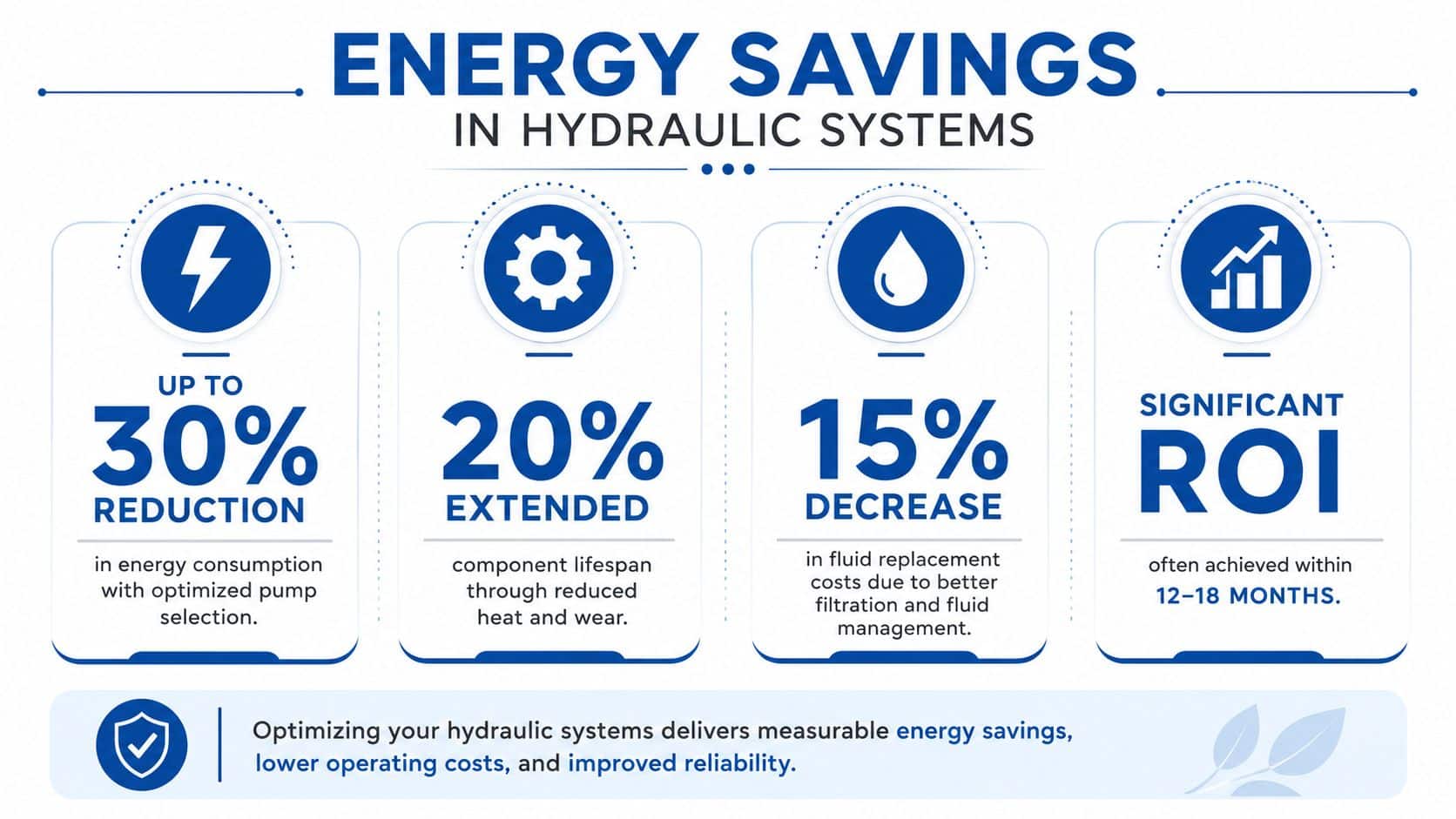
That model is expensive to operate and difficult to justify when efficiency has become a serious design criterion. The wider market is moving the other way. The UK hydraulic equipment market is projected to grow at a CAGR of 12.1% through 2035, driven by industrial modernisation and equipment efficiency initiatives, according to Brennan's UK hydraulics market overview.
Cut losses where they are created
The biggest wins usually come from reducing wasted flow and unnecessary pressure drop.
Focus on these areas:
- Variable speed drives on power packs: when motor speed follows demand, the system stops producing flow it doesn't need.
- Accumulator use where duty suits it: stored hydraulic energy can smooth intermittent peaks and reduce repeated demand spikes.
- Valve and pipework review: pressure drop across the wrong points often explains chronic heat problems.
- Removing routine throttling where possible: if a machine controls speed by burning off excess flow, redesign deserves a look.
Research aligned with UK hydraulic applications also notes a gap in practical guidance around right-sizing systems for variable load profiles and removing functional flow throttling in control valves, as highlighted in this recent off-road hydraulics paper. That gap is real in the field. Many machines still carry flow capacity they rarely need.
A broader operational view helps as well. Plant managers looking at the full utilities picture may find useful ideas in this guide to cutting business energy costs, especially when hydraulic efficiency is part of a wider site energy review.
Monitoring beats assumptions
Video often helps teams visualise where savings come from in a live circuit. This overview is a useful reference point.
The next step is to monitor the system after changes instead of assuming the design improvement has delivered what was intended.
Useful checks include:
- Pressure trend before and after modification
- Oil temperature stability across the same duty
- Motor loading through a normal shift
- Cycle consistency at beginning and end of operation
Predictive maintenance belongs in the same conversation
Predictive maintenance is often discussed separately from energy performance, but the two are linked. Sensor-based monitoring helps engineers catch blocked filters, leakage growth, and unstable temperatures before those conditions turn into waste and downtime.
Current industry discussion around hydraulic systems highlights the value of IoT-enabled smart controls and real-time monitoring, while also noting the lack of recent UK-specific field data on ROI and failure prediction for smaller bespoke power packs, as described in this sustainable hydraulics article. That doesn't make monitoring less useful. Instead, engineers should be disciplined about proving value on their own equipment.
For teams reviewing practical methods to lower hydraulic waste, energy consumption reduction approaches in hydraulics should be tied to measured outcomes, not supplier claims.
Validating Gains and Calculating Your ROI
If the post-modification measurements don't go back to the original baseline points, the result is opinion, not validation. The same pressure locations, the same operating mode, and the same temperature state should be used again after changes are made. That's the only fair comparison.
What to confirm after the work
A proper validation pass should answer four questions:
- Has the machine become more stable under the duty that mattered?
- Has oil temperature become easier to control?
- Has the operator stopped compensating for sluggish or erratic behaviour?
- Has maintenance demand shifted from reactive replacement to planned service?
Use the baseline sheet again and compare the before and after condition side by side. If the numbers are better but the machine still behaves poorly, there is probably another restriction or control problem still in the circuit.
A practical ROI framework
Hydraulic ROI is usually built from three areas:
| ROI element | What to include |
|---|---|
| Energy | Reduced motor demand, lower heat load, less cooler workload |
| Maintenance | Fewer premature part changes, less contamination damage, less fault-finding time |
| Production | Improved cycle consistency, fewer stoppages, less operator intervention |
You don't need a complicated financial model to begin. A simple internal worksheet is enough. For teams that want a refresher on the commercial side, this article on how to calculate profit margin is a useful reminder that engineering improvements only become business wins when the savings are tied back to actual cost and margin.
Example one, mobile agricultural machine
An operator reports weak low-speed control, oil heating during long field use, and repeated seal attention. Baseline checks show the machine performs acceptably when cold, then becomes inconsistent as temperature rises.
The improvement work might include correcting component matching, reducing avoidable throttling, and improving filtration and cooling practice. Costs would usually be grouped in pounds sterling across parts, labour, and testing time. The payback assessment should then compare energy use, service demand, and machine availability before and after the change.
Example two, industrial power pack
A compact industrial power pack shows pressure instability during load changes and a tendency to run hotter than expected through repeated cycles. The machine still functions, so the issue has been tolerated for some time.
A sensible optimisation project would re-check pressure settings, valve behaviour, temperature control, and the baseline flow performance of the pump. If the pack sees variable demand, engineers may also review whether a different control strategy would reduce waste. The ROI usually becomes clear when the system stops drifting thermally, the response becomes repeatable, and maintenance intervention drops.
Validation should be boring. If the gains are real, the readings are repeatable and the machine simply behaves better every day.
The strongest hydraulic projects aren't the ones with the most dramatic language around them. They're the ones where the machine runs cooler, responds properly, wastes less energy, and stops consuming maintenance time for avoidable reasons.
MA Hydraulics Ltd supports UK engineers, OEMs, and MRO teams with hydraulic components, bespoke power packs, and practical application guidance for performance optimization. If you need help reviewing a system, matching components, or discussing a power pack build, contact MA Hydraulics Ltd. Phone 01724 279508 today, or send us a message.
