
A maintenance engineer arrives at a mobile plant expecting a routine hose replacement. The pump is isolated, but a second circuit still holds pressure because the installed valve was intended for low-pressure water service rather than hydraulic isolation. The handle turns, yet the system can't be treated as safely shut off until the circuit is properly relieved and tested.
That situation explains why ball valve hydraulic selection needs more thought than choosing a quarter-turn handle. The valve must suit the fluid, pressure, temperature, bore, connection and duty. It must also belong to the correct standards environment. A plumbing ball valve and a high-pressure hydraulic isolation valve may look similar, but they aren't interchangeable.
Introduction to Hydraulic Ball Valves in UK Systems
A hydraulic ball valve is primarily an on-off isolation device. Inside the body, a drilled ball rotates through a quarter turn. With the bore aligned with the pipe, fluid passes through. Rotate the ball across the passage and the seats close around it, stopping flow through the valve.
That simple action has practical value for OEMs, MRO teams and mobile plant operators. A technician can isolate part of a circuit quickly before removing a hose, changing a motor, inspecting an actuator or working on a manifold. In agriculture, materials handling and manufacturing, controlled isolation supports safer maintenance and helps reduce the amount of equipment that needs to be taken out of service.
The wider UK market gives this component a substantial engineering context. The UK fluid power market was estimated at around £1.1 billion in 2024, with hydraulics representing roughly 80% of the total, while UK manufacturers' total fluid power equipment sales, including exports, fell by around 10% to £1.4 billion in 2024, according to the UK fluid power market data. That scale reflects a large installed base, continuing replacement demand and a mature technical standards environment.
The first decision is therefore not “which handle looks right?” It's “what job must the valve perform?”
- Isolation: Shut off a branch, hose, actuator or service section.
- Diversion: Direct flow between circuit paths with a suitable three-way arrangement.
- Control: Regulate flow or pressure continuously, which usually calls for another valve family.
- Safety: Provide a clearly identified isolation point that forms part of a documented maintenance procedure.
This guide separates true hydraulic isolation from potable-water applications, then works through operating principles, pressure ratings, materials, competing valve types, selection and maintenance. It uses metric terminology and UK English throughout. If supplier comparisons show prices in another currency, convert them to GBP before making a procurement decision.
How Hydraulic Ball Valves Work and Control Flow
A machine is ready for maintenance, but a trapped hydraulic line still holds pressure. The operator turns the ball-valve handle through a quarter turn to close the passage. That simple movement works like a tap, yet a hydraulic valve must contain pressurised fluid and withstand the loads generated by the circuit.
The parts that determine behaviour
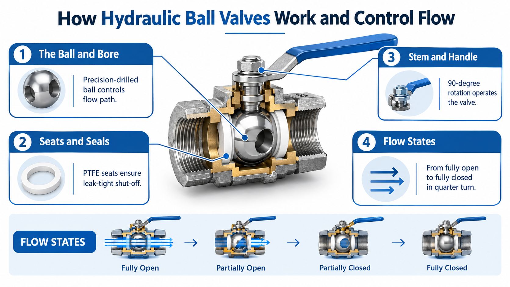
The ball has a precision-drilled bore. With the valve open, the bore aligns with the ports and creates a direct flow path. With the valve closed, the solid side faces the ports, while the seats press against the ball to limit leakage.
The seats form the sealing interface between the ball and body. Their material must suit the hydraulic fluid, temperature and pressure. The stem transfers movement from the handle or actuator to the ball, and stem seals prevent fluid escaping around the rotating shaft.
A two-way valve has an inlet and outlet, so its usual role is line isolation. A three-way valve includes another port. Its internal arrangement can select, divert or combine flow paths. The MA Hydraulics three-way ball valve guide shows how port configuration affects the available flow states.
Full bore and reduced bore
A full-bore valve keeps its internal passage close to the connected line size. It normally creates less restriction when open. A reduced-bore valve has a smaller passage, which can increase pressure drop and reduce flow capacity.
Reduced bore can still suit a compact circuit with modest flow, provided the pressure-drop effect has been checked. Connection size alone does not prove that the valve offers an unrestricted passage. The bore, fluid viscosity, required flow and operating pressure all affect the result.
Practical rule: Select the bore from the required flow and acceptable pressure drop, not from the handle size alone.
Ball valves are generally suited to isolation because the ball moves between defined open and closed positions. Standard designs are not intended to remain partly open for continuous flow control. Throttling can expose the ball and seats to high velocity, turbulence and contamination. Wear may increase, and repeatable control becomes difficult.
Contamination is a reliability issue, not just a cleanliness issue. Debris can mark a seat, prevent full closure or damage the sealing surfaces. A valve may appear closed while leaking through a damaged seat, trapped particles or a worn stem interface.
Opening a closed valve against an unexpected pressure differential can also produce a sudden flow event. Follow the circuit isolation procedure, relieve stored pressure and confirm the system state. Handle position alone does not prove that the hydraulic line is safe.
The operating principle is straightforward. Reliable isolation depends on the correct pressure capability, bore and cleanliness for the application.
Check that the embedded video displays within a correctly sized frame, particularly on mobile screens. Incorrect sizing can hide operating details and make the demonstration difficult to follow.
Standards Materials and Pressure Ratings Explained
A brass ball valve on a building water service may look much like a valve on a hydraulic power unit. The visual similarity is misleading. Plumbing standards, hydraulic pressure classes, bore sizes and fluid compatibility describe different duties, so the handle shape cannot establish suitability.
Start with the applicable standard
In the UK, BS EN 13828:2025 covers manually operated copper alloy and stainless-steel ball valves for potable water supply in buildings. It supersedes BS EN 13828:2003, as described in the BS EN 13828:2025 reference. That reference can support plumbing procurement, but it does not replace a hydraulic specification. Both products may use a rotating ball while having very different pressure, testing and service requirements.
For metal ball valves, BS EN ISO 17292:2015 is the current UK implementation of the international standard. It superseded BS EN ISO 17292:2004, which replaced BS 5351:1986. The standard covers DN 8 to DN 600, with pressure designations including Class 150, 300, 600 and 800, and PN 16, 25, 40, 63 and 100, according to the ISO standard listing.
Read the complete product documentation. Check the data sheet, nameplate and product image for the stated standard, connection, material and pressure designation. A wrong reference can affect procurement, inspection and acceptance testing. The image must agree with the written specification before publication or purchase.
Materials and temperature
Carbon steel and stainless-steel bodies can suit demanding industrial service, while brass is common in lower-pressure arrangements. The body, ball and stem are separate material decisions. Corrosion exposure, fluid chemistry, temperature and mechanical loading all influence whether the construction is appropriate.
Seats and seals need the same scrutiny. A compound compatible with mineral hydraulic oil may not suit another fluid or a higher operating temperature. Confirm the manufacturer's limits for the complete valve, including the fluid, temperature and pressure combination. A familiar seal code alone does not prove compatibility.
For teams comparing material technologies, explore AAM material offerings as a separate resource when considering how material choice and manufacturing approach fit the component environment. It does not replace the selected valve manufacturer's pressure, fluid and temperature documentation.
Pressure changes with size
A pressure rating belongs to a defined design and size range. One UK data sheet gives a PN30 brass three-way valve as an example. Its limits reduce as the nominal size increases, which is a useful warning against applying one rating across an entire product family. The same data sheet gives a working temperature range of -20°C to +120°C, with the pressure limits varying by size, as shown in the three-way ball valve data sheet.
| Nominal size | Working pressure | Selection implication |
|---|---|---|
| 1/4 to 3/4 inch | 30 bar | Higher stated pressure within this listed size range |
| 1 to 1 1/4 inch | 20 bar | Confirm the rating before upsizing the connection |
| 1 1/2 to 2 inch | 16 bar | Do not assume the smaller-size rating still applies |
Hydraulic products show a wider spread again. UK supplier data lists 3,000 psi for certain ball-valve sizes and up to 20,000 psi, or 1,378 bar, for another medium-pressure line, as shown by UK ball-valve pressure-range data. Convert imperial examples into bar before comparing them with a metric hydraulic circuit, then check the exact size, port configuration and service conditions.
STAUFF defines nominal pressure as the admissible working overpressure at +20°C and states a burst-pressure safety factor of at least 2.4 times nominal pressure in its hydraulic-component catalogue. Use that as catalogue-specific engineering information, not as a universal substitute for the selected valve's certification. Temperature, pressure peaks, bore size and contamination can all affect real-world reliability, so the final choice must match the complete circuit duty.
Ball Valves Compared with Other Hydraulic Valve Types
A ball valve solves a different problem from a CETOP directional valve. Confusing those functions can leave a circuit technically connected but operationally wrong.
A ball valve isolates. A directional control valve routes flow to an actuator. A proportional valve varies flow or pressure in response to a control signal. Needle valves regulate manually through a restricted passage, while check valves permit flow in one direction and prevent reverse flow.
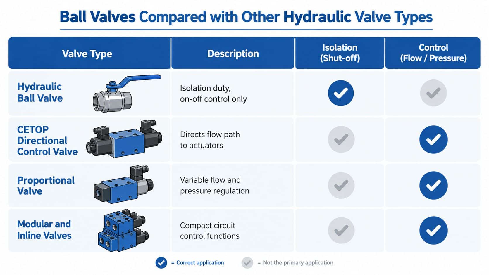
| Circuit requirement | Suitable valve family | What it does |
|---|---|---|
| Isolate a branch or component | Hydraulic ball valve | Provides on-off shut-off |
| Send flow to different actuator paths | CETOP directional control valve | Changes the flow route |
| Adjust flow or pressure continuously | Proportional valve | Provides variable control |
| Add compact circuit functions | Modular or inline valve | Integrates functions near the manifold or line |
| Restrict flow manually | Needle valve | Offers fine adjustment, with an associated pressure drop |
| Stop reverse flow | Check valve | Allows one-way passage |
Isolation is not metering
A standard ball valve has a useful open position and a useful closed position. At an intermediate position, the partially exposed seat and ball can experience turbulence and high local velocity. That can accelerate seat wear and make the relationship between handle position and flow unpredictable.
A needle valve is better suited to manual adjustment where the operator needs controlled restriction. A proportional valve is appropriate when the machine must vary flow or pressure in response to an input. A CETOP valve belongs where the circuit needs repeatable directional switching, often through a manifold or subplate arrangement.
Modular and inline valves also have distinct roles. They may provide check, pressure-control, flow-control or other functions within a compact hydraulic assembly. Their mounting format matters as much as their internal function, particularly where a machine uses a standard manifold layout.
Choose from the circuit task
Ask what must happen after the operator moves the control. If the answer is “the branch must be safely shut off for service”, a hydraulic ball valve may be suitable. If the answer is “the actuator must extend at a controlled rate”, a ball valve is the wrong starting point.
A quarter-turn handle tells you how a valve operates. It doesn't tell you what the circuit needs the valve to do.
Three-way ball valves deserve particular care because the port arrangement determines whether the valve diverts, mixes or isolates paths. Confirm the flow diagram against the actual circuit before installation. A familiar body shape doesn't guarantee the required connection between ports.
How to Select the Right Hydraulic Ball Valve
A service engineer arrives at a machine that needs safe isolation, but the installed valve is a plumbing type with an unsuitable pressure rating and a restricted bore. The handle still turns, yet the valve may not provide dependable hydraulic isolation. Selection should begin with the circuit, then move to pressure, bore, contamination, connections and operation.
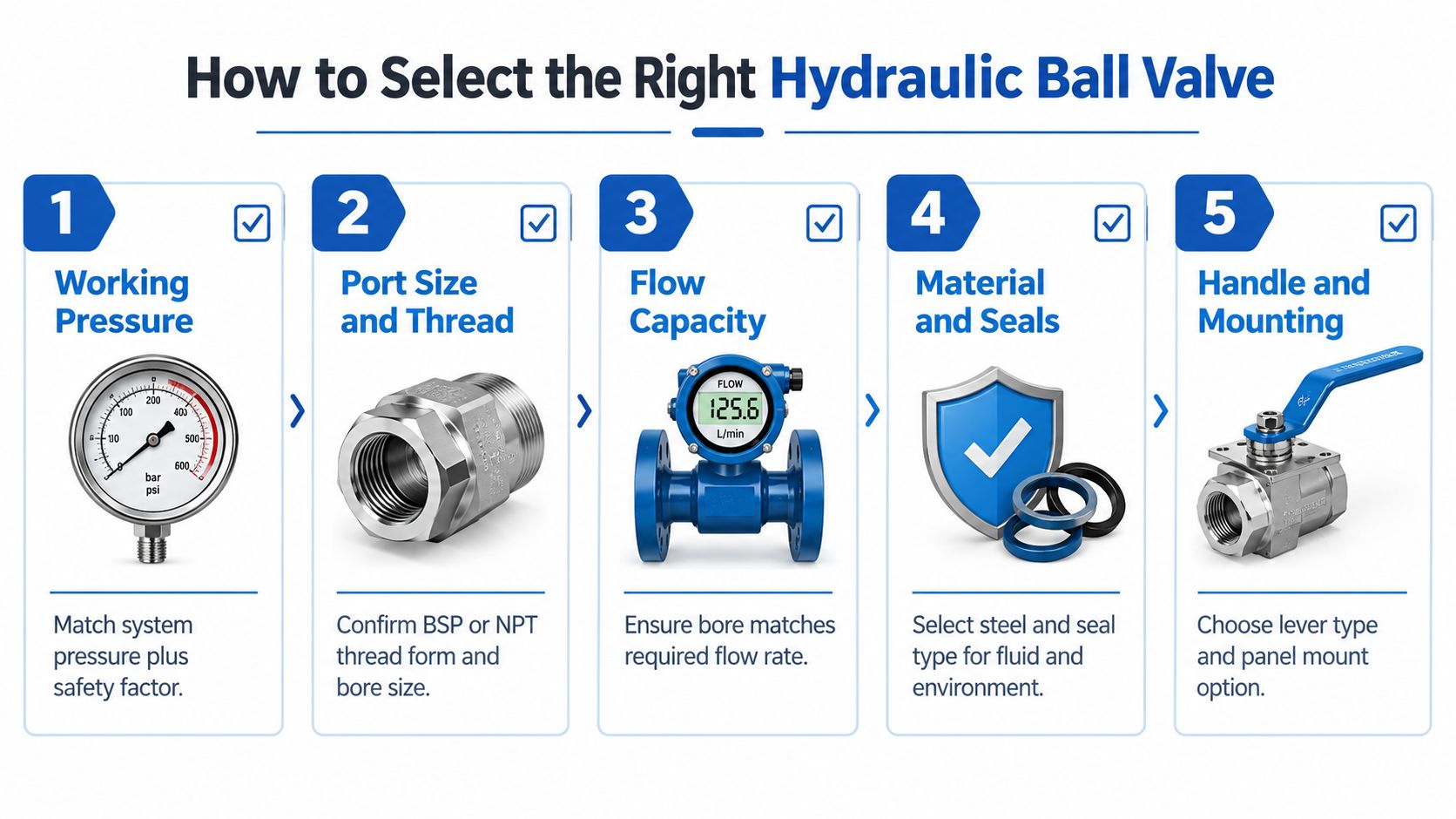
1. Confirm working pressure
Record the system's maximum working pressure, normal operating pressure and any pressure spikes created by the application. Compare these values with the valve's admissible working pressure at the expected temperature. The word “hydraulic” in a product description does not, by itself, confirm suitability.
Use the manufacturer's technical documentation for the selected valve. The STAUFF catalogue explains nominal pressure as admissible working overpressure at +20°C and gives a burst safety factor of at least 2.4 times nominal pressure. Treat those figures as product information, then confirm the exact model, temperature range and duty before ordering.
2. Match ports, threads and bore
Identify the connection standard, such as BSP or NPT, and check whether the valve has female, male, tube or flange connections. Threads can appear to fit while using the wrong form, leaving the joint unable to seal correctly.
Record pipe and tube dimensions in metric units. If a legacy component is identified in inches, retain that detail for cross-reference, then verify the replacement's actual bore and connection specification.
3. Check flow capacity
A full-bore valve generally suits circuits where pressure drop must remain low. A reduced-bore valve can suit lower flow demand or tighter installation space. Compare published flow data with the circuit requirement. A larger external body does not necessarily provide a larger internal passage.
Bore size also affects contamination tolerance. Fine particles can obstruct a restricted passage or damage seats, so filtration and cleanliness should be considered alongside nominal flow.
4. Validate materials and seals
Check the hydraulic fluid, ambient conditions, temperature and exposure to contamination or washdown. Brass, carbon steel and stainless steel bodies offer different levels of suitability, while seat and stem-seal compounds must be compatible with the medium.
A dusty agricultural machine, corrosive washdown area and clean indoor power unit may need different materials even when their pressure requirements are similar.
5. Decide how it will be operated
A lever suits a visible manual isolation point. Pneumatic or electric actuation may suit a guarded machine or remote control requirement, but the actuator must match the required torque, control method and safe-state response. For these interfaces, consult the MA Hydraulics actuator ball valve information.
Before ordering, cross-reference body markings, port arrangement, seal material, pressure rating and handle orientation. Ask the supplier to confirm availability, lead time and GBP pricing. If a catalogue shows a USD example, record the current UK equivalent in pounds rather than comparing currencies informally.
Installation and Maintenance Best Practices
Most hydraulic ball-valve problems don't begin with the handle. They begin with contamination, unsupported pipework, incorrect sealing, pressure left in the circuit or a seal that has been ignored because the valve operates only occasionally.
Install cleanly and without imposed stress
Keep protective caps in place until connection. Clean the line, inspect the threads and prevent sealant from entering the flow passage. Support adjacent pipework so tightening the valve doesn't turn it into a structural brace.
Orient the handle where operators can identify open and closed positions safely. Leave enough clearance for inspection and removal. If the valve is fitted into a manifold or compact assembly, make sure nearby components don't obstruct the handle, stem or actuator.
Don't use the handle as a spanner. Tighten the connection using the correct method for the fitting, then inspect for distortion or misalignment.
Make isolation a controlled process
Before service, stop the machine, isolate the energy source and depressurise the circuit. A closed valve doesn't prove that downstream pressure has disappeared. Use the machine's approved test points and verify the pressure state before loosening a connection.
Maintenance guidance for valves emphasises inspecting the valve and stem interface, depressurising before service, checking seals and mounting parts, retightening or replacing seats and stem seals after use, then carrying out pressure and leakage testing, as set out in the valve maintenance guidance.
Inspect even when operation is rare
A valve that moves only during an annual shutdown still faces ageing, contamination and seal deterioration. Set an inspection interval based on the duty, environment and manufacturer's instructions. Record the inspection rather than relying on someone remembering the last check.
Look for:
- Stem weeping: Inspect the stem seal area and confirm that fluid isn't tracking from a nearby connection.
- Stiff operation: Check for contamination, pressure differential, misalignment or seal degradation. Never force the handle.
- Leakage when closed: Verify the ball position, relieve pressure safely and inspect the seats for damage or debris.
- Pressure loss when open: Check bore size, contamination, incorrect installation and restrictions elsewhere in the line.
- Loose mounting: Examine brackets, panel mounts and adjacent pipework for imposed loads.
After maintenance, perform the required pressure and leakage tests before returning the circuit to service. Any embedded video used in a work instruction should have a correctly sized frame, with a 16:9 aspect ratio where appropriate, so technicians can see the valve position and test sequence without distorted controls.
For installation detail on related inline components, use the MA Hydraulics inline valve installation guide.
Next Steps for Specifying Your Hydraulic Ball Valve
A sound specification starts with the circuit duty. Confirm whether the valve provides isolation, diversion or another function, then record working pressure, temperature, fluid compatibility, bore, connection form and operating method. These details prevent a plumbing valve from being selected for a high-pressure hydraulic job because both products have a ball and handle.
Use the earlier standards discussion as a check, not as a substitute for the manufacturer's datasheet. Confirm the exact valve family, pressure rating at the required temperature, material, seal compound and connection specification. A PN30 marking alone does not describe every size, port arrangement or service condition.
Before releasing the part for purchase, work through this short checklist:
- Match the pressure rating to both normal and trapped pressure conditions.
- Select a bore that supports the required flow without creating avoidable pressure loss.
- Check fluid cleanliness, contamination risk and the valve's suitability for the circuit.
- Confirm thread form, port orientation, mounting space and handle clearance.
- Use metric dimensions in drawings and purchasing records, with GBP for UK cost comparisons.
- Check the part number and datasheet against the written specification.
For application advice, cross-references, stocked components and bespoke power-pack support from Scunthorpe, phone MA Hydraulics Ltd on 01724 279508 today or send a message through the MA Hydraulics contact page.
MA Hydraulics Ltd can help match a hydraulic ball valve to circuit pressure, bore, fluid, actuation and installation constraints, whether you need a replacement or components for a complete system. Visit MA Hydraulics Ltd to discuss hydraulic components, cross-references and bespoke power solutions with the team.
