
A hydraulic power pack can be correctly rated on paper and still waste energy every time the machine pauses. A fixed-speed motor keeps turning, a pump keeps producing flow, and the relief valve converts surplus hydraulic power into heat while the cylinder waits for its next command. That pattern appears in fabrication shops, presses, mobile lifting equipment and process machinery across the UK.
Hybrid power solutions address the mismatch between installed power and actual demand. They combine variable-speed drives, energy storage, complementary prime movers and intelligent controls so the hydraulic circuit receives power when it needs it, rather than continuously at a catalogue rating. The right design isn't just a battery added to a conventional power pack. It starts with the duty cycle, then matches the motor, pump, accumulator, controls and thermal system to the measured load.
The UK grid is also changing the engineering case. Renewable electricity supplied 47% of UK electricity in 2025, while gas supplied 28%, nuclear 11% and net imports 10%, according to Carbon Brief's analysis of UK electricity generation. For hydraulic equipment, that makes dispatch timing, storage and load management increasingly important. The practical question is not whether hybridisation sounds efficient. It's whether the architecture survives motor inrush, peak cylinder loads, cold weather, poor solar conditions, maintenance constraints and the response demands of the machine.
Why Hybrid Power Solutions Matter for Modern Hydraulics
A typical Midlands fabrication shop runs a fixed-speed hydraulic power pack for a press brake. During the active bend, the pump supplies substantial flow and pressure. During dwell, positioning or operator handling, the hydraulic demand falls sharply, yet the electric motor continues operating at full speed. If the circuit unloads through a valve, the motor still consumes power and the oil still absorbs heat. If flow remains available across a relief valve, the losses are even more direct.
That arrangement was often accepted because fixed-speed motors, gear pumps and simple unloading circuits were familiar, reliable and easy to service. The weakness appears in the duty cycle. A machine with short high-load events and long idle periods gets sized around its peak requirement, then runs inefficiently for much of the shift. Oversizing the motor and cooler doesn't solve that mismatch. It often makes the idle penalty, starting current and cabinet footprint worse.
Hybrid power solutions change the power path. A variable-speed drive can reduce motor speed when flow demand falls. An accumulator can store hydraulic energy during low-demand periods and release it during a fast cylinder movement. A battery or secondary generator can support transient loads without forcing the primary prime mover to carry every peak. The hydraulic circuit still performs the work, but the energy source follows the machine's actual demand more closely.
The commercial pressure is not limited to electricity consumption. Industrial teams face energy-management obligations, including the need to understand significant energy use under the UK's Energy Savings Opportunity Scheme. Mobile equipment designers must also consider Stage V emissions requirements, operator noise and the increasing expectation that plant should reduce unnecessary engine idling. A hybrid design can help, but only when its controls and components are specified around the load profile.
Practical rule: Don't start with the battery size or motor rating. Start with pressure, flow, time and the frequency of each operating event.
A useful early review should record loaded strokes, holding periods, unloading time, starts per hour, oil temperature and the worst-case simultaneous functions. The sustainability practices guidance from MA Hydraulics provides relevant context for treating efficiency as a system-design issue rather than a single-component purchase. The rest of the design then becomes a question of selecting the simplest architecture that can meet those measured requirements.
Core Architectures Behind Hybrid Hydraulic Systems
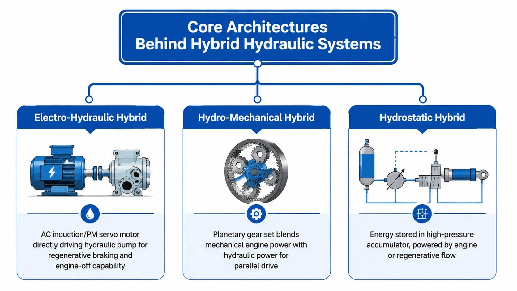
Hybrid hydraulic systems fall into several practical families. The three most useful for industrial and mobile applications are electro-hydraulic, diesel-electric-hydraulic and battery-hydraulic arrangements. A fourth category, hydro-mechanical or hydrostatic storage, can also be important where an accumulator or mechanical transmission provides the buffering function.
Electro-hydraulic arrangements
The electrical path is straightforward: a three-phase supply feeds a variable frequency drive, the drive controls an AC induction or permanent-magnet motor, and the motor turns a fixed or variable-displacement pump. In an industrial installation, the electrical side commonly centres on a 400 V AC supply. An accumulator sits on the hydraulic side, connected through suitable valves and protection devices, and supplies short-duration peaks when the motor and pump would otherwise need to be sized for them.
Think of the accumulator as a hydraulic flywheel. It stores energy in compressed gas and returns it quickly, while the electric motor supplies the average requirement. The drive can slow the motor during low flow demand, then increase speed when the accumulator pressure or machine command calls for more hydraulic power.
Diesel-electric-hydraulic systems
For mobile plant, a diesel engine can drive a generator that supplies a DC bus. Inverter-fed electric motors then drive one or more hydraulic pumps. A battery or supercapacitor bank connects to the DC bus and handles fast changes in demand, while the engine runs closer to its efficient operating region instead of following every valve movement.
Mobile DC systems may use architectures ranging from 48 V to 800 V DC, depending on power, packaging, insulation and safety requirements. The hydraulic accumulator can still be added to the circuit, giving the designer two storage layers. Electrical storage handles electrical transients and engine decoupling. Hydraulic storage handles rapid flow delivery directly at the actuator.
Battery-hydraulic systems
A battery-hydraulic unit removes the combustion engine from the local power path. The battery feeds an inverter, the inverter drives an electric motor, and the motor drives the hydraulic pump. This suits indoor machinery, urban mobile equipment and applications where local exhaust emissions or noise are unacceptable.
Storage sits upstream of the motor and pump, so the battery management system must account for peak current, temperature and state of charge. The hydraulic circuit still needs conventional protection, filtration, cooling and emergency discharge arrangements. A battery-led machine isn't automatically simpler. It replaces engine and fuel-system tasks with high-voltage isolation, thermal management, charging strategy and electrical diagnostics.
The control architecture matters as much as the hardware. A closed-loop hydraulic system approach can coordinate pressure, flow and actuator position, but the feedback signals must be selected for the actual machine response rather than added as a generic upgrade.
Comparing Benefits and Trade-Offs Across Architectures
No hybrid architecture wins every application. A 24-hour injection moulding line with long holding periods has a different requirement from a telehandler that spends short periods lifting, travelling and braking. The first needs quiet, repeatable flow control and thermal stability. The second needs rapid transient power, mobile packaging and reliable operation away from a large electrical connection.
| Criterion | Electro-Hydraulic (VFD + Accumulator) | Diesel-Electric-Hydraulic | Battery-Hydraulic |
|---|---|---|---|
| Energy reduction potential | Strong where idle running and throttling dominate | Strong where engine loading is highly variable | Strong where engine idling and local generation are avoidable |
| Peak power handling | Accumulator supports short hydraulic peaks | Battery or supercapacitor supports bus transients, with engine providing sustained power | High-discharge battery and inverter must support the complete peak profile |
| Capital cost | Moderate to high, depending on drive, pump and storage | High, due to generator, DC bus, inverters and controls | High, with battery, charger, inverter and safety systems |
| Footprint | Usually compact for fixed plant | Larger because it combines engine, generator and hydraulic equipment | Packaging depends heavily on battery volume and cooling |
| Noise | Low at reduced motor speed | Engine noise remains, although engine-off operation may be possible during selected functions | Lowest local noise potential |
| Grid dependency | Requires a suitable industrial supply | Can operate independently of the grid | Requires charging infrastructure or a separate energy source |
| Maintenance complexity | Adds drive and controls to familiar hydraulic maintenance | Adds generator, power electronics and battery service | Removes engine maintenance but adds battery and high-voltage procedures |
A 24/7 injection moulding machine often favours the electro-hydraulic route. A variable-speed motor can reduce speed during hold and cooling periods, while an accumulator can provide fast injection or clamp transitions if the circuit is designed for it. The designer must still check motor cooling at low speed, pump efficiency across the pressure range and the effect of pressure ripple on valve performance.
A mobile telehandler has a different balance. A diesel-electric-hydraulic system can separate engine operation from hydraulic demand and use stored electrical energy for rapid lift peaks. Claims about fuel reduction must be validated against the measured cycle. The hybrid hardware adds inverters, isolation, software and diagnostic requirements that an MRO team must be able to support. HVO compatibility may be attractive for some diesel arrangements, but it must be confirmed for the selected engine and fuel system rather than assumed.
Battery-hydraulic equipment provides the clearest route to zero local combustion emissions, but continuous high-flow work can create battery and inverter heat. Cold conditions can also reduce available battery performance, which is particularly relevant to UK mobile plant. Three-phase 400 V AC availability may make an industrial electro-hydraulic system practical, while a large VFD installation can still require careful coordination with the distribution network operator. Grid-connected projects may face connection limits even when the machine's annual energy requirement looks manageable.
For variable industrial loads, consider a digital displacement pump option where controllable displacement is more valuable than varying motor speed. The best architecture is the one that handles the dominant load pattern with the fewest unnecessary conversion stages.
Design and Integration Considerations for Real Duty Cycles
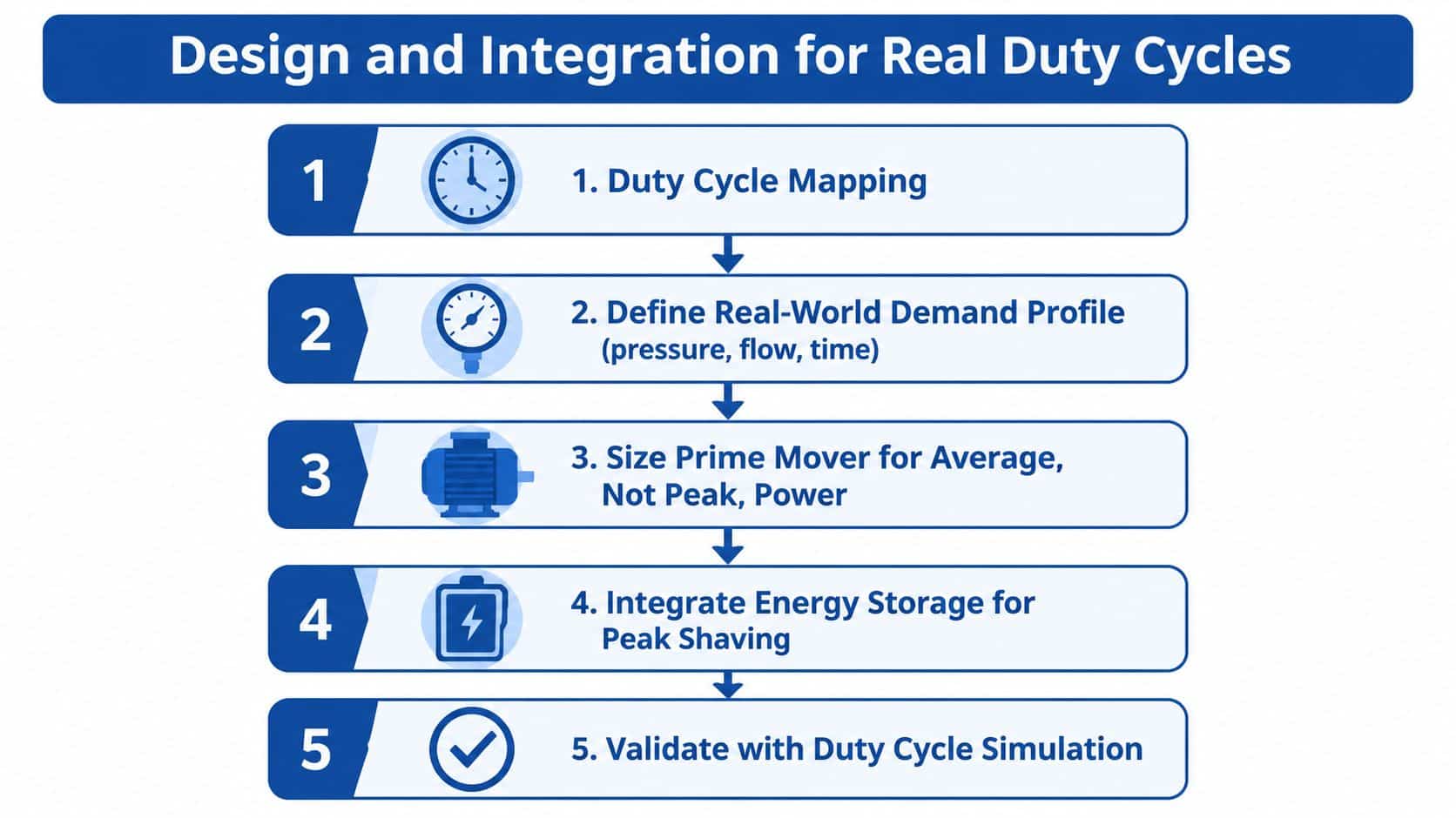
Catalogue peak power is a poor basis for hybrid sizing. A hydraulic system may reach its maximum cylinder force for a short pressing event, draw high flow during extension, and spend most of its operating time holding position or waiting for the next cycle. The prime mover should be selected against the measured average and sustained demand, while storage and controls handle peaks that are short and repeatable.
Begin with a duty-cycle capture. Record pressure and flow at the pump outlet, actuator speed, motor current, oil temperature and the timing of each function. For mobile machinery, include travel, braking, steering, auxiliary hydraulics and engine warm-up. Motor inrush also needs separate treatment. A large induction motor can impose a severe starting event even when its running demand is modest, so a VFD, soft-start arrangement or battery-supported DC bus may be necessary.
Match control logic to the machine
Pressure-flow decoupling prevents the prime mover from responding to every small valve movement. A variable-speed pump can regulate flow at the source, while a proportional or servo valve controls the actuator with the required precision. An accumulator can then cover rapid demand changes, provided its pre-charge, usable volume and pressure limits match the cycle.
Pre-charge is not a set-and-forget value. Too much pre-charge reduces usable stored oil volume and can cause poor pressure support. Too little can increase bladder movement, reduce responsiveness and create an unsuitable operating range. The control system should monitor pressure, state of charge and temperature, then define clear thresholds for assist, recharge, engine start and shutdown.
Energy recovery needs a deliberate circuit path. A descending load can drive a hydraulic motor or pump, sending energy into an accumulator or through a regenerative electrical drive. A counterbalance valve still has to control the load safely. It shouldn't be bypassed to chase recovery, because uncontrolled overrunning can create instability, overspeed or a dangerous loss of load control.
The UK grid's carbon intensity varies with generation conditions. Live GB data has shown a point at around 64 gCO2/kWh, while renewables supplied roughly 45.5% of generation at that time, as recorded by Energy Dashboard's live electricity data. The engineering response is to tune charging, export and grid import logic to actual timing, not to treat installed renewable capacity as an automatic emissions result.
Safety check: Stored hydraulic and electrical energy must have a defined dissipation path before anyone relies on an emergency stop.
Emergency stop sequencing should isolate prime movers, prevent unintended actuator movement, discharge stored energy where safe, and preserve any functions required for controlled load descent. The design and risk assessment should address BS EN ISO 4413, electrical isolation, accumulator protection, safe maintenance access and verification after commissioning.
The following video can help engineers visualise the relationship between hydraulic demand and hybrid control, but embedded media should be checked on the finished page for correct frame sizing and responsive behaviour.
Selecting Pumps, Motors, Valves and Power Packs
Component selection should follow the measured operating envelope. A variable-displacement axial-piston pump is useful when pressure and flow vary widely and the control system can exploit that range. A fixed gear pump remains attractive for simpler auxiliary functions, intermittent circuits and applications where low cost, uncomplicated servicing and predictable direction of rotation matter more than fine modulation.
The electric motor must be checked at the actual torque-speed points, not just its nameplate rating. Low-speed operation can affect cooling, while repeated acceleration can impose thermal stress even when average power is modest. Permanent-magnet servo motors offer precise control, but they bring drive compatibility, encoder and service considerations. Induction motors with VFDs may be easier for an industrial maintenance team to understand and replace.
| Component | Selection criteria | Typical application fit |
|---|---|---|
| Pump | Displacement control, pressure range, volumetric efficiency at operating temperature, allowable speed and flow ripple | Variable industrial loads, mobile auxiliary circuits or steady-duty functions |
| Electric motor | Torque-speed envelope, starting method, cooling at low speed, enclosure and duty rating | VFD-driven power packs, battery-electric mobile units and regenerative drives |
| Hydraulic motor | Continuous and intermittent torque, speed range, case-drain requirements, starting efficiency and allowable pressure | Wheel drives, winches, fans and regenerative load circuits |
| Valve assembly | Response time, leakage, proportionality, contamination tolerance and fail-safe position | Servo positioning, pressure control, load holding and sequencing |
| Reservoir and cooler | Heat rejection, aeration control, return velocity, filtration and available installation space | Compact mobile packs and high-cycle industrial machinery |
| Accumulator | Bladder or piston suitability, usable volume, gas service, pressure rating and isolation method | Peak shaving, emergency movement and energy recovery |
| Power pack | Modular manifold or integrated assembly, access for service, noise control and electrical protection | OEM builds, retrofit units and bespoke industrial installations |
Valve choice is often where a promising design loses its practical advantage. A proportional valve can't compensate for poor signal scaling, excessive deadband or contaminated oil. Servo valves demand greater cleanliness and control quality. For a sturdy MRO installation, a proportional CETOP or inline valve arrangement may offer a better balance than a high-performance servo circuit.
Reservoir sizing also needs more than a volume rule. A compact mobile pack must prevent aeration, allow heat rejection and provide enough separation time for entrained air. If the system relies on lower motor speed to reduce heat generation, verify that the cooler still performs across the full ambient range and that low-flow operation doesn't create local hot spots.
For UK OEMs and plant teams, MA Hydraulics Ltd supplies hydraulic components, assembles Hydronit DC electric pump BULL sets in 12 V and 24 V for battery-powered mobile applications, and builds Hydronit and bespoke industrial power-pack solutions, including in-house industrial units up to 11 kW. That type of supplier input is most useful when the discussion starts with the duty cycle, pump displacement, valve function and service conditions rather than a preferred brand.
Maintenance, Lifecycle Costs and ROI Planning
Hybrid power solutions move cost rather than eliminating it. Upfront expenditure rises because the system may need a VFD, accumulator, battery, inverter, sensors, protection equipment and software. Ongoing energy cost can fall where the baseline system spends substantial time unloading, throttling or idling, but the result must be demonstrated from operating data.
A defensible business case compares the existing machine with the proposed architecture over the intended service life. Use logged motor current, machine hours, pressure and flow, then apply the site's actual electricity or fuel costs. Include cooling, hydraulic oil condition, filter replacement, battery inspection, drive servicing, downtime and the cost of specialist fault-finding. Avoid inserting an assumed payback period into the purchase justification without validating the duty cycle.
Build the cost model around failure modes
A hybrid system has new failure points. Power electronics can be affected by heat, contamination and poor enclosure selection. Batteries need health monitoring and safe isolation. Accumulators require inspection, correct pre-charge and protection against unauthorised intervention. Hydraulic components still face contamination, seal ageing, hose damage and thermal degradation.
Maintenance planning should assign responsibility for each layer:
- Hydraulic service: Monitor oil cleanliness, filter condition, leakage, temperature and accumulator pre-charge.
- Electrical service: Inspect connections, cooling paths, drive alarms, isolation devices and motor bearings.
- Energy storage: Check battery condition, thermal data, state-of-charge limits and charging equipment.
- Controls validation: Confirm pressure sensors, speed feedback, emergency-stop logic and fault responses.
- Parts strategy: Hold critical seals, filters, valves and electrical spares according to actual failure consequences.
The UK storage market shows why service capability matters. Utility-scale battery storage reached 7.5 GW of installed power capacity in 2025, with 2.3 GW energised during that year. Great Britain's grid-scale batteries produced 2.3 TWh and recorded average annual efficiency of 85%, according to the UK government's grid-scale battery storage statistics. Those figures describe grid assets rather than hydraulic machines, but they underline the scale at which battery management, controls and maintenance are becoming established engineering disciplines.
The model should also test operational scenarios. What happens if the battery is cold, the accumulator has lost pre-charge, the grid connection is limited or the engine must run continuously? A system that delivers its expected result only under ideal conditions isn't a reliable investment.
Application Scenarios for OEMs, MRO Teams and Plant Engineers
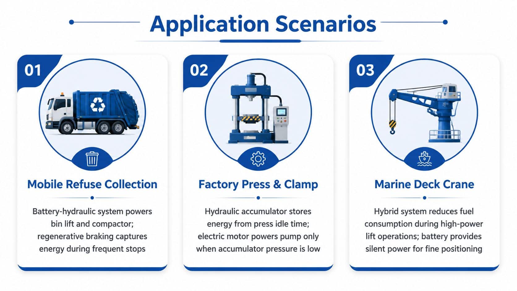
Three UK applications show how the architecture should follow the duty rather than the marketing label.
Mobile refuse collection
A refuse collection vehicle has frequent stops, repeated bin-lift movements and hydraulic compaction events. The diesel engine may be sized for road travel and peak hydraulic demand, even though the hydraulic functions operate intermittently around the collection route.
A battery-hydraulic arrangement can drive the bin lift and compactor from an electric motor when the vehicle is stationary. Regenerative braking can return energy to the battery during repeated deceleration, subject to the vehicle's electrical and control architecture. A high-discharge battery, inverter-fed motor, variable-displacement pump and load-sensing valve block would be sensible starting points. The result can include lower engine idling, reduced local noise and less heat generation during waiting periods, but the battery must be sized for the route's actual lifting and compaction sequence.
Retrofitted factory press
An MRO team working on an older hydraulic press should first measure the existing pump flow, pressure, motor current, idle dwell and cycle timing. Replacing a fixed-displacement pump and unloading valve with a variable-speed electro-hydraulic drive may reduce unnecessary circulation and soften motor starting, but the retrofit must preserve cylinder response, pressure holding and emergency movement.
An accumulator can support rapid press movement or clamp events if the pressure envelope and safety arrangements allow it. The manifold should include isolation, pressure monitoring and safe discharge. Site engineers also need to check the three-phase supply, drive harmonics, cabinet ventilation and available fault level before specifying a large VFD. A retrofit that saves hydraulic energy but creates nuisance trips on the factory network hasn't solved the plant problem.
Seasonal aggregate processing
An aggregate processing line may run hard during production periods and at reduced capacity during colder or quieter conditions. A diesel-electric-hydraulic arrangement can use a generator and DC bus to decouple engine speed from hydraulic demand, while battery or supercapacitor storage handles short transients.
The plant engineer should size the engine for sustained demand, not every simultaneous startup, then confirm that the storage system can cover the peak without excessive thermal stress. Winter operation requires particular attention to battery temperature, diesel starting, oil viscosity and solar availability where PV forms part of the site supply. Hybrid control should define when the engine starts, when storage assists, and how the system behaves during low-fuel or low-charge conditions.
For finance and operations teams assessing equipment without buying the whole asset outright, understanding how products as a service works can add a useful commercial perspective. It encourages the team to consider uptime, service responsibility, replacement risk and measurable output alongside the initial equipment price.
When to Choose Hybrid Power Solutions and Next Steps
Hybrid power solutions make the strongest engineering case where the machine has frequent peaks, long holding or idle periods, repeated deceleration, noise constraints or local emissions requirements. They also suit sites where storage can reduce peak electrical demand or where a generator can run independently from variable hydraulic activity.
A conventional power pack may remain the better choice for a simple, steady load with low annual operating hours. Extra controls and storage won't repay themselves if the machine rarely cycles, has little throttling loss and already operates close to its prime mover's efficient point.
The decision should come from a measured duty cycle, not a headline efficiency figure. OEMs, MRO teams and plant engineers can contact MA Hydraulics for a no-obligation duty-cycle assessment, component specification review or retrofit feasibility study matched to the hydraulic application and site conditions.
MA Hydraulics Ltd can help specify pumps, valves, motors, accumulators and bespoke power packs for industrial and mobile hydraulic duty cycles, including battery-led and variable-speed arrangements. Visit MA Hydraulics Ltd, phone 01724 279508 today, or send us a message to discuss your application.
