

A mobile machine can spend much of its working day alternating between heavy loading, precise movement and near-idle running. A conventional hydraulic circuit may still drive the pump at a level suited to the highest demand, then discard surplus energy across valves as heat. The operator sees a familiar machine response, while the maintenance team sees rising fluid temperature, cooling demand and fuel use.
A digital displacement pump changes where the system makes its decisions. Instead of producing a broadly available flow and restricting it downstream, the pump can select how many pumping elements contribute to each part of the cycle. That makes the technology relevant to excavators, off-highway equipment, industrial power units and emerging electrically driven hydraulic systems.
The important question for a UK retrofit isn't whether the pump can be efficient on a test rig. It's whether the benefit survives mixed-duty operation, existing pipework, legacy controls, hydraulic noise, commissioning time and the cost of supporting the machine in service. The principles of hydraulic circuits remain useful, so engineers unfamiliar with the technology may find this guide to how hydraulics work a useful foundation.
Introduction to Digital Displacement Pumps for Modern Hydraulics
Why the operating cycle matters
Consider an excavator lifting a load, slewing, positioning its attachment and then waiting for the next instruction. Each task needs a different combination of pressure and flow. Conventional variable pumps can reduce displacement, but many systems still rely on proportional valves and throttling to control actuators. The pressure drop across those restrictions becomes heat rather than useful movement.
A digital displacement pump approaches the same cycle by controlling the pumping action closer to its source. It can supply flow when a cylinder needs it and reduce contribution when demand falls. That doesn't mean every installation automatically delivers the same saving. The valves, controller, sensors, motor or engine, pipework and actuator all remain part of the energy path.
A UK-developed technology with practical scale
The technology has a long UK engineering history. Work began at the University of Edinburgh in the early 1990s, following earlier concepts in 1984 and prototype work in 1990. Artemis Intelligent Power formed in 1994, and the first 1.5 kW pump powerpack demonstration took place in 1998, according to the University of Edinburgh's archived Digital Displacement publication.
The same historical record places the technology on a much larger footing by 2014, when a 7 MW wind turbine installation in Scotland demonstrated that the approach had moved beyond small experimental hardware. That progression matters to retrofit engineers because it shows both a research lineage and experience with demanding power transmission.
Practical rule: Treat the pump as part of a complete hydraulic architecture, not as a drop-in replacement for a conventional pump.
What this guide is designed to clarify
For a design engineer, the attraction is controllable flow with lower avoidable losses. For a fleet operator, the concern is payback during real work rather than an idealised test. For a service engineer, the questions include valve condition, fluid cleanliness, software diagnostics, sensor calibration and the availability of replacement parts.
Those concerns are connected. A pump may show strong efficiency at a chosen operating point but deliver less benefit if the legacy circuit continues to throttle heavily, if energy recovery isn't commissioned correctly, or if the controller lacks accurate pressure and speed information. Understanding that chain is the starting point for a sound specification.
How a Digital Displacement Pump Works and Is Controlled
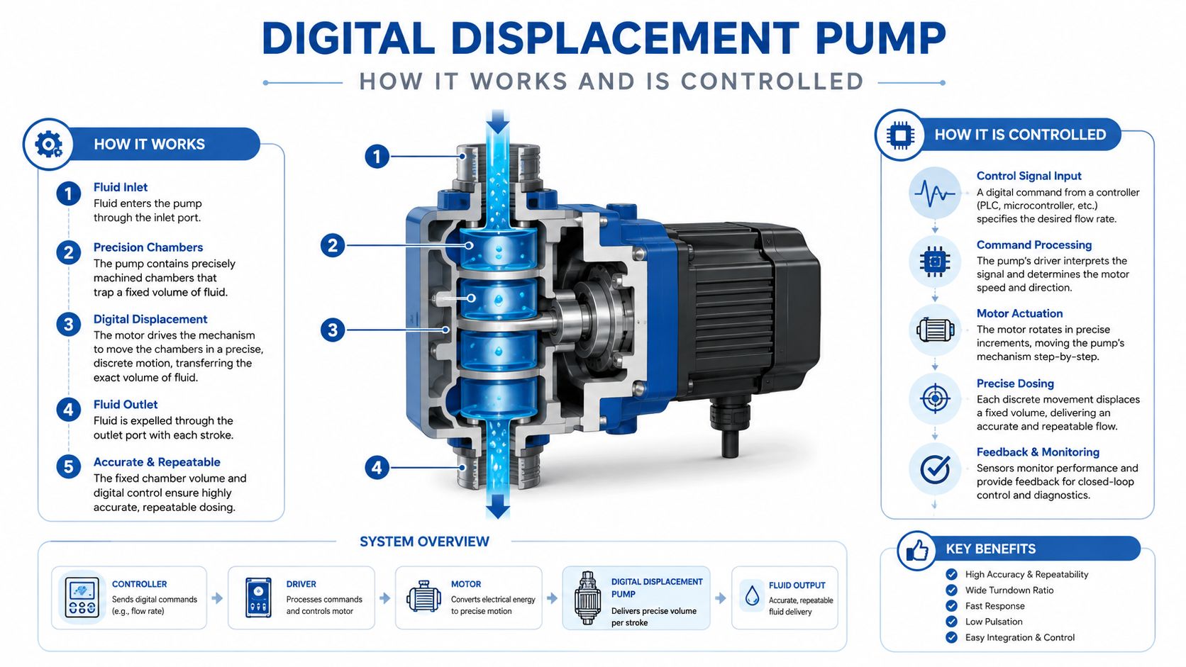
A conventional pump often changes displacement through a mechanical arrangement such as a swashplate. The pump remains a hydraulic machine with a continuously varying output, and the wider circuit controls where that flow goes. A digital displacement pump divides the task into individually controlled pumping elements.
The cylinder-level decision
Think of the pump's cylinders as a bank of small contributors. At any point in shaft rotation, the controller decides which cylinders should compress and deliver fluid, and which should remain unloaded. The comparison with digital bits is useful: each cylinder has a controlled contribution, and the combined result forms the required flow.
The mechanism is more precise than a simple on or off switch. Ultra-fast mechatronic valves control the hydraulic state of each cylinder, while embedded electronics use shaft position, pressure and command information to make decisions in real time. The controller can therefore match delivered flow to actuator demand rather than relying solely on a downstream restriction.
Why the arrangement can reduce losses
The University of Bath describes the central advantage clearly in engineering terms. Individually actuated cylinders and real-time control allow precise flow management while reducing leakage and throttling losses, which can improve efficiency compared with conventional pump arrangements. The same University of Bath research on the Digital Displacement Pump also identifies an important trade-off, reduced inherent damping can increase transmitted vibration and fluid-borne noise in the hydraulic circuit.
That trade-off is easy to miss. A conventional circuit can absorb some pressure fluctuations through restrictions and compliance. A fast digital system removes unnecessary restriction, but the designer must then manage pulsation, resonance, hose routing, accumulator behaviour and controller tuning.
Control is part of the pump
The pump won't deliver its intended behaviour through hydraulic hardware alone. The control system must understand requested flow, available pressure, shaft speed and the operating limits of the prime mover. It must also respond safely to sensor faults, valve errors, excessive temperature and unexpected load changes.
This is why digital displacement shouldn't be compared only with a pump catalogue entry. It may replace or reduce the role of a conventional proportional control arrangement, but it introduces a greater dependence on electronics, software and commissioning. Engineers familiar with proportional valve control will recognise the same need for stable command signals and predictable feedback, although the control point has moved closer to the pump's individual cylinders.
Digital Displacement Versus Conventional Pumps Compared
The right choice depends on the duty cycle and the rest of the circuit. A conventional variable pump can remain the sensible option where the machine has stable demand, established service procedures and limited appetite for control-system change. Digital displacement becomes more compelling where frequent load changes, energy recovery, multiple outputs or electrification expose the losses of traditional architecture.
The table below is a design aid, not a substitute for testing the actual machine.
Digital Displacement Pump Versus Conventional Variable Pump Comparison
| Criterion | Digital Displacement Pump | Conventional Variable Pump |
|---|---|---|
| Part-load efficiency | Can control cylinder contribution directly, reducing unnecessary flow and throttling losses | Can reduce displacement, but downstream valves and restrictions may still dissipate energy |
| Flow control | High-resolution, real-time control at cylinder level | Mechanical displacement control, often combined with valves |
| Response | Fast electronic valve actuation can support rapid command changes | Response depends on pump compensator, swashplate dynamics and circuit control |
| Noise and vibration | Reduced damping can increase pressure pulsation, vibration and fluid-borne noise if the circuit isn’t tuned | Restrictions and hydraulic compliance may damp some fluctuations, though they create losses |
| Integration | Requires sensors, embedded control, software and suitable electrical architecture | Familiar interfaces and established commissioning methods |
| Maintenance | Needs attention to valves, electronics, fluid cleanliness, sensors and diagnostics | Focuses on mechanical control elements, seals, bearings, valves and contamination |
| Best fit | Mixed-duty, multi-output or electrified systems where control and efficiency justify added complexity | Proven, simpler installations with predictable demand and existing support capability |
The underlying pump principles remain common to the wider positive-displacement family. Engineers comparing architectures may also benefit from this positive displacement pumps guide, particularly when reviewing fixed-volume displacement, pressure behaviour and maintenance implications.
Efficiency isn't only a pump figure
A pump's volumetric behaviour, leakage and pressure losses affect the result at the actuator. The practical meaning of volumetric efficiency in hydraulic systems is therefore important during comparison. A component can appear attractive in isolation while the completed machine loses the advantage through undersized pipework, poor control tuning, relief-valve activity or an actuator that operates far from its useful range.
Digital displacement also creates responsibilities. The control software must be supported, replacement valves must be available and the service team must understand diagnostic information. If the application cannot justify that additional system work, a conventional variable pump may offer a lower-risk lifecycle decision even if its peak efficiency is less attractive.
Where Digital Displacement Pumps Deliver Value in Real Systems
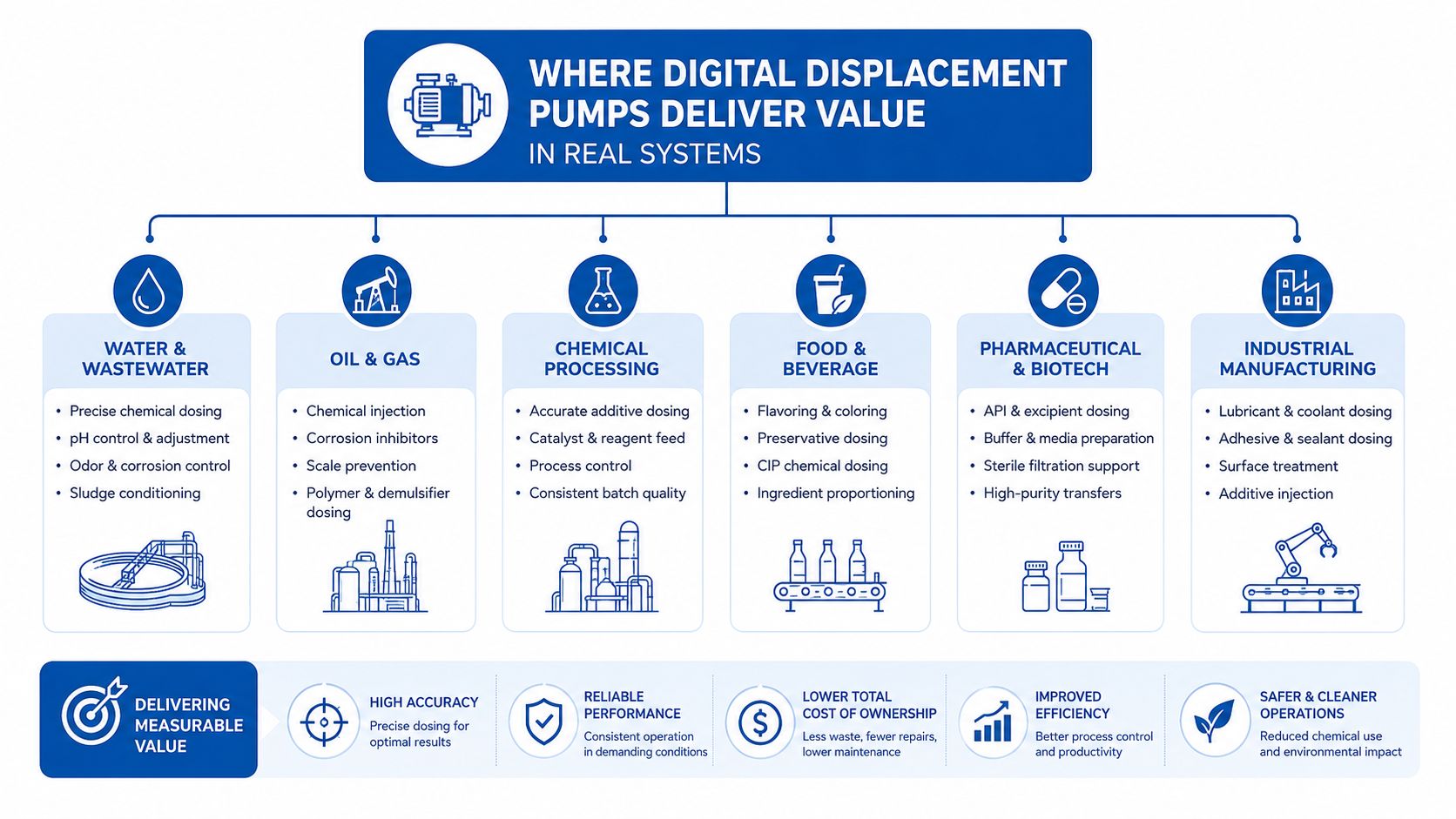
Digital displacement earns its strongest case where demand changes repeatedly and the machine can make use of accurate flow allocation. Excavators are a clear example because boom, arm, bucket and slew functions can impose different pressure and flow requirements within the same working sequence.
Evidence from excavators and transmissions
UK-linked University of Edinburgh work gives the technology a useful practical reference point. In one excavator study, average pump efficiency rose from 82.1% to 91.5%, with whole-machine fuel savings of up to 21% in efficiency mode and productivity gains of 10%. The same source reports 91% shaft-to-shaft efficiency at full power for another Edinburgh transmission study, with a projected 93% in an operational system. These figures are reported in the University of Edinburgh transmission and excavator study.
The figures don't mean every retrofit will reproduce the result. They show where value can appear, especially when the control strategy reduces wasted flow and the machine's duty cycle contains enough variable demand to reward that control.
Industrial and emerging uses
The technology also suits hydraulic power transmission, marine-energy equipment and wind applications. The UK research record includes assessment of Digital Displacement hydrostatic transmission for tidal current energy converters, where efficiency and dynamic performance were both relevant engineering considerations, as described in the tidal current energy converter paper.
Newer architectures extend the idea beyond one pump feeding one circuit. UK coverage describes digital displacement pumps using embedded control and fast mechatronic valves for electric off-highway systems. A 2026 UAV example shows a UK-developed digital displacement pump distributing power to four hydraulic rotors, according to Danfoss's new-generation pump information. That example is a projection of where the architecture is being applied, not proof that every small hydraulic system needs it.
A useful way to judge fit is to ask:
Does the machine spend enough time away from one steady operating point for controllable displacement, energy recovery or independent outputs to repay the added integration work?
An excavator, electrically driven power unit or multi-output machine may answer yes. A simple, lightly loaded circuit with predictable flow may not.
The following video provides another visual introduction to the technology and its application context.
How to Select and Specify a Digital Displacement Pump
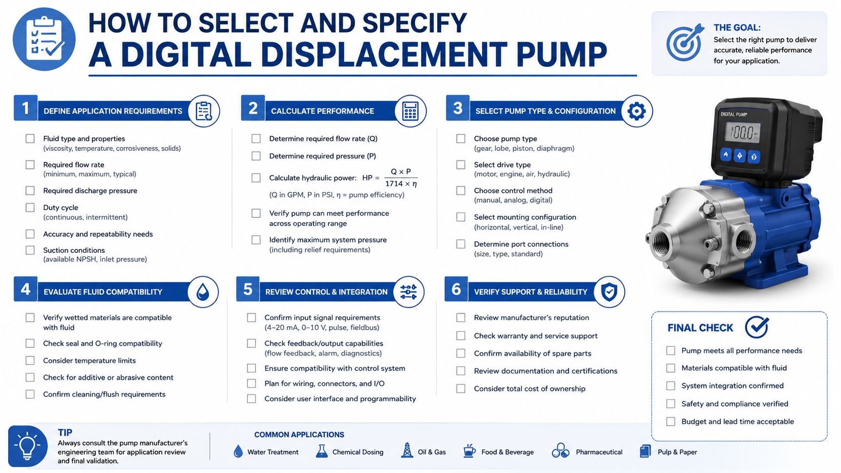
Selection should start with the machine's duty cycle, not the pump label. Record pressure, flow, shaft speed, direction, temperature and operating duration across representative tasks. A peak requirement alone can lead to an oversized pump that spends much of its time operating inefficiently or a controller that cannot manage the transition into low-demand work.
Start with the hydraulic envelope
Define the required flow in litres per minute, pressure in bar, shaft speed in revolutions per minute and fluid temperature in degrees Celsius. Include standby, start-up, shock loading and relief events. If the pump will drive several functions, establish whether those functions need simultaneous flow, priority control or independent pressure management.
Then examine the prime mover. An engine-driven pump may need coordination with engine speed and fuel demand. An electric motor and inverter may offer a different operating envelope, but the electrical supply, cooling and control response must support the hydraulic commands.
Test the full efficiency path
Independent University of Edinburgh work measured Digital Displacement Pump Motor round-trip efficiency between 63% and 87% under varying pressure, displacement and shaft-speed conditions. The same study measured excavator boom energy-recovery efficiency at 31% in JCMAS testing, while simulation suggested it could rise to 64% after system changes, as reported in the University of Edinburgh repository study.
Those results are a useful warning against choosing on a headline figure. Ask the supplier for efficiency maps covering the actual pressure, speed and displacement range. For an energy-recovery system, request separate data for capture, storage, conversion and reuse. A recovery path that performs well only during a narrow boom movement may not justify its additional hardware in a mixed-duty fleet.
Price the engineering, not just the component
No verified GBP purchase price is available here, so a sound specification shouldn't pretend to offer a universal figure. Build a UK lifecycle estimate from the pump, valves, controller, sensors, wiring, software work, manifold changes, installation, commissioning, training, planned maintenance and spares.
A procurement review can also include adjacent diagnostic disciplines. For example, teams responsible for electrical protection may find this practical resource on interpreting ground fault results useful when reviewing inverter and motor fault information alongside hydraulic alarms.
The final specification should state acceptance tests, expected operating points, noise limits, filtration requirements, control fallback behaviour and data logging. That makes later payback analysis credible because the team can compare measured machine work with the original duty-cycle assumptions.
Integration and Retrofit Considerations for UK Hydraulic Systems
Retrofitting a digital displacement pump into an existing machine is a system redesign. The old pump may connect to a familiar manifold, PTO, reservoir, cooler, controller and valve block. Replacing it without reviewing those interfaces can move the restriction elsewhere and leave much of the expected efficiency gain unrealised.
The UK scale-up context
Public discussion has often centred on flagship research and new-build equipment, while the practical retrofit path receives less attention. UK evidence shows that the technology is still moving from pilot activity towards manufacturing scale. APC-backed work in Scotland is associated with a new Loanhead facility and a £21 million programme, as recorded in the UK government project document.
That matters for buyers because manufacturing availability, technical support and replacement strategy influence lifecycle risk. A promising prototype still needs a supply chain, documented diagnostics and serviceable interfaces before a fleet manager can treat it like routine hydraulic equipment.
Retrofit checkpoints
Use the first machine as an engineering validation, not as proof that every machine in the fleet will behave identically.
- Hydraulic circuit: Map existing restrictions, relief settings, accumulators, hose sizes, return paths and actuator leakage before selecting the replacement.
- Mechanical installation: Check shaft alignment, mounting, PTO compatibility, coupling loads, access for service and cooling requirements.
- Electrical architecture: Confirm motor or engine control, inverter capacity, sensor wiring, earthing and protection arrangements.
- Software behaviour: Define command priorities, safe states, fault handling, start-up sequencing and manual recovery modes.
- Energy recovery: Measure where recovered energy goes and whether the storage or reuse path suits the actual work cycle.
- Commissioning: Test pressure, flow, temperature, noise, vibration and machine productivity at representative tasks.
- Fleet economics: Compare fuel or electrical consumption, output, downtime, parts and technician time rather than relying on pump efficiency alone.
Why mixed-duty results vary
A recent Edinburgh excavator retrofit measured 63% to 87% round-trip efficiency, while energy recovery rose from 31% to 64% in the reported system work after proposed changes. Those results show that architecture and control changes can materially influence the outcome, but they also demonstrate why a legacy machine needs measurement before and after conversion.
For UK application advice on a bespoke power unit, hydraulic integration or retrofit feasibility, phone 01724 279508 today, or send a message through MA Hydraulics Ltd's contact page.
Maintenance and Troubleshooting to Protect Efficiency Gains
Efficiency can disappear gradually through contamination, calibration drift or a control fault that forces the system into a conservative operating mode. Digital displacement systems need conventional hydraulic discipline plus attention to high-speed valves, sensors, electronics and software diagnostics.
Workshop checks that protect performance
- Fluid cleanliness: Maintain the specified filtration and investigate recurring contamination rather than repeatedly replacing valves.
- Valve condition: Look for delayed response, inconsistent flow, abnormal leakage or fault records associated with individual pumping elements.
- Sensors: Check pressure, speed, temperature and position feedback against calibrated test equipment during planned service.
- Connections: Inspect plugs, harnesses, earth points and enclosure seals for moisture, vibration damage or poor contact.
- Hydraulic condition: Check fluid level, aeration, temperature, hose condition and unusual pressure fluctuations.
- Data records: Compare current pressure, speed and flow behaviour with commissioning data so deterioration becomes visible before a breakdown.
Use symptoms to narrow the fault
A rise in fluid temperature may indicate throttling, excessive leakage, a relief setting problem or a controller that isn't delivering the intended displacement strategy. Slow actuator response can result from a sensor issue, valve command fault, air ingress, restricted filtration or a change in the load circuit.
Vibration and fluid-borne noise deserve structured investigation. The University of Bath work identifies reduced inherent damping as a possible consequence of digital control, so don't assume every noise complaint means a failed pump. Check pressure pulsation, hose support, accumulator condition, valve timing, resonance and mounting before changing major components.
Service principle: Record the operating condition when the symptom appears. Pressure, speed, temperature and commanded flow often reveal more than a fault code alone.
MA Hydraulics Ltd can help with component cross-references, hard-to-find hydraulic parts, bespoke power packs and after-sales troubleshooting where an existing installation needs a practical repair or system review. Contact MA Hydraulics Ltd to discuss your digital displacement pump application, retrofit measurements or hydraulic power-pack requirements, and phone 01724 279508 today or send a message through the contact page.
