
A conveyor on a Midlands food-production line starts tripping whenever the product load rises. The motor nameplate appears adequate, yet the shaft slows, the gearbox runs hot and the maintenance team is called back to the same fault. The problem may not be a defective motor. It may be that the motor speed, reduction ratio, output torque, duty cycle and contamination controls were never considered as one system.
That distinction matters across UK manufacturing, materials handling, agriculture and mobile plant. The UK industrial gearbox and gear motors market recorded a 15.22% increase in imports from 2023 to 2024, alongside a 5.72% compound annual growth rate between 2020 and 2024, a pattern described as part of a sustained recovery rather than a single spike. UK industrial gearbox and gear motors market data points towards a growing installed base and stronger demand for application-specific sourcing, replacement support and technical cross-referencing.
What Gearbox Motors Are and Where They Fit
A gearbox motor pairs a motor with gearing so the output shaft turns more slowly while delivering higher usable torque than the motor shaft alone. The motor may be electric, hydraulic or pneumatic. Gearing changes the balance between speed and torque, but it does not create power. Mechanical losses remain, and they appear mainly as heat.
For a conveyor, auger, winch or indexing table, start with the driven shaft. Define its required speed, torque, starting load, stopping frequency, reversing duty and radial loading under the hardest operating condition. Nameplate motor power is only one part of that decision. Duty cycle, efficiency and contamination control often determine whether the drive runs reliably over its service life.
The reduction ratio links a fast motor to a slower machine shaft. A clear explanation of what a reduction gearbox does helps establish the mechanical principle. A higher reduction ratio can provide greater output torque at lower speed, subject to efficiency, thermal capacity and the gearbox's permitted load.
Three product families
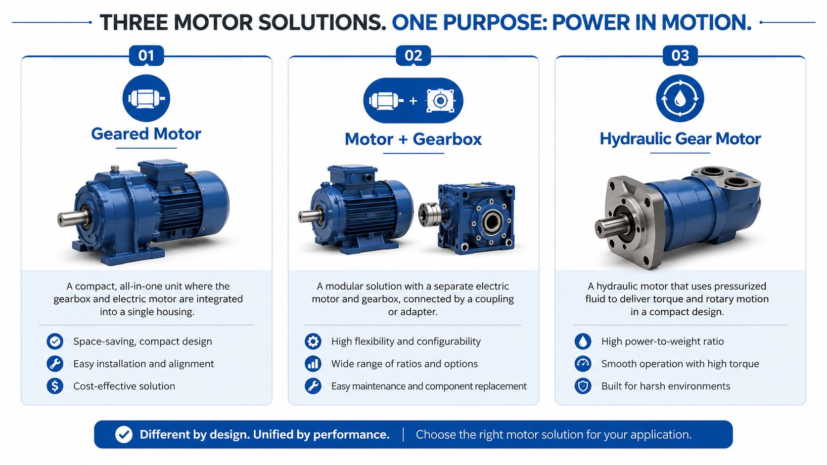
Engineers commonly see three arrangements on quotations:
- Integrated electric geared motor: The motor and gearbox are supplied as one matched unit, usually with a combined specification and compatible mounting.
- Motor plus gearbox: A separate motor connects to the gearbox through a flange, coupling or bellhousing. This can simplify replacement choices, provided shaft dimensions, alignment, mounting and ratings are compatible.
- Hydraulic gear motor: Pressurised fluid drives gears inside a hydraulic motor housing. It suits machines that already have hydraulic power and require compact rotary drive.
The arrangement also sets the maintenance workload. Electric units require attention to electrical protection, cooling, seals and gearbox lubrication. Hydraulic gear motors add fluid cleanliness, filtration, seal condition and circuit pressure. In dusty, wet or washdown environments, contamination control can matter as much as the selected ratio, because contaminated oil or ingress accelerates wear in gears, bearings and seals.
The UK has a long history of gearbox engineering. John Dixon Abbott patented a change-speed and reversing gearbox suitable for motor-trams in 1909. Henry Meadows was founded in Wolverhampton in 1920 as a car gearbox maker. Improved Gears Ltd was incorporated in 1928 and later became Self-Changing Gears, associated with patented pre-selective epicyclic gearbox technology used in Leyland buses. This history of Self-Changing Gears records the development and industrialisation of these British gearbox architectures before modern automation drives became commonplace.
Gear Technologies Compared Without the Jargon
The simplest way to compare gear technologies is to think about how each one moves load through the gearbox.
A worm gearbox is like a screw turning a toothed wheel. The input and output shafts usually sit at a right angle, the movement is quiet and the arrangement can achieve substantial reduction in a compact space. That makes worm drives familiar on conveyors, mixers, gates and other mechanisms where slow movement and straightforward packaging matter.
The trade-off is sliding contact between the worm and wheel. That generally creates more heat and lower efficiency than a well-selected helical arrangement. Some worm drives resist back-driving at standstill, but you shouldn't assume that feature provides a safe holding brake. If a suspended or hazardous load must remain stationary, specify and test a suitable brake or mechanical holding device.
A helical gearbox uses angled teeth that engage progressively, much like two carefully meshing ramps rather than two blunt blocks. The result is smooth torque transmission, lower noise and a strong general-purpose option for conveyors, pumps, fans and industrial machinery. UK technical guidance reports a helical bevel drive delivering 1.5 kW at 82 rpm, with monitored drive efficiency improving to 81% and actual power draw falling to 0.48 kW in the reported industrial case. The Engineer's report on Flender Motox geared motors illustrates why the complete drivetrain matters more than output speed alone.
A planetary gearbox resembles a compact solar system. A central sun gear drives several planet gears, which rotate inside a surrounding ring. Multiple contact paths share the load, allowing high torque density in a relatively compact coaxial package. Planetary systems often suit cyclic, reversing, high-load or precision applications, although the specification must still account for backlash, lubrication, thermal capacity and shock.
A practical comparison
| Technology | Typical strength | Main concern | Often considered for |
|---|---|---|---|
| Worm | Compact right-angle reduction and quiet operation | Sliding losses, heat and possible efficiency penalty | Conveyors, mixers and slower mechanisms |
| Helical | Smooth running, strong efficiency and broad industrial usefulness | Axial and radial loads must be managed correctly | Materials handling, pumps and production machinery |
| Planetary | High torque density and compact coaxial construction | More demanding specification and service requirements | Cyclic, reversing and precision machinery |
UK listings show that the market also includes bevel, right-angle, in-line helical spur, hollow-shaft, solid-shaft and motorised variator arrangements, alongside worm and planetary options. UK geared motor and gearbox listings demonstrate why “gearbox motor” isn't a sufficient specification by itself.
The Seven Specifications That Drive a Real Choice
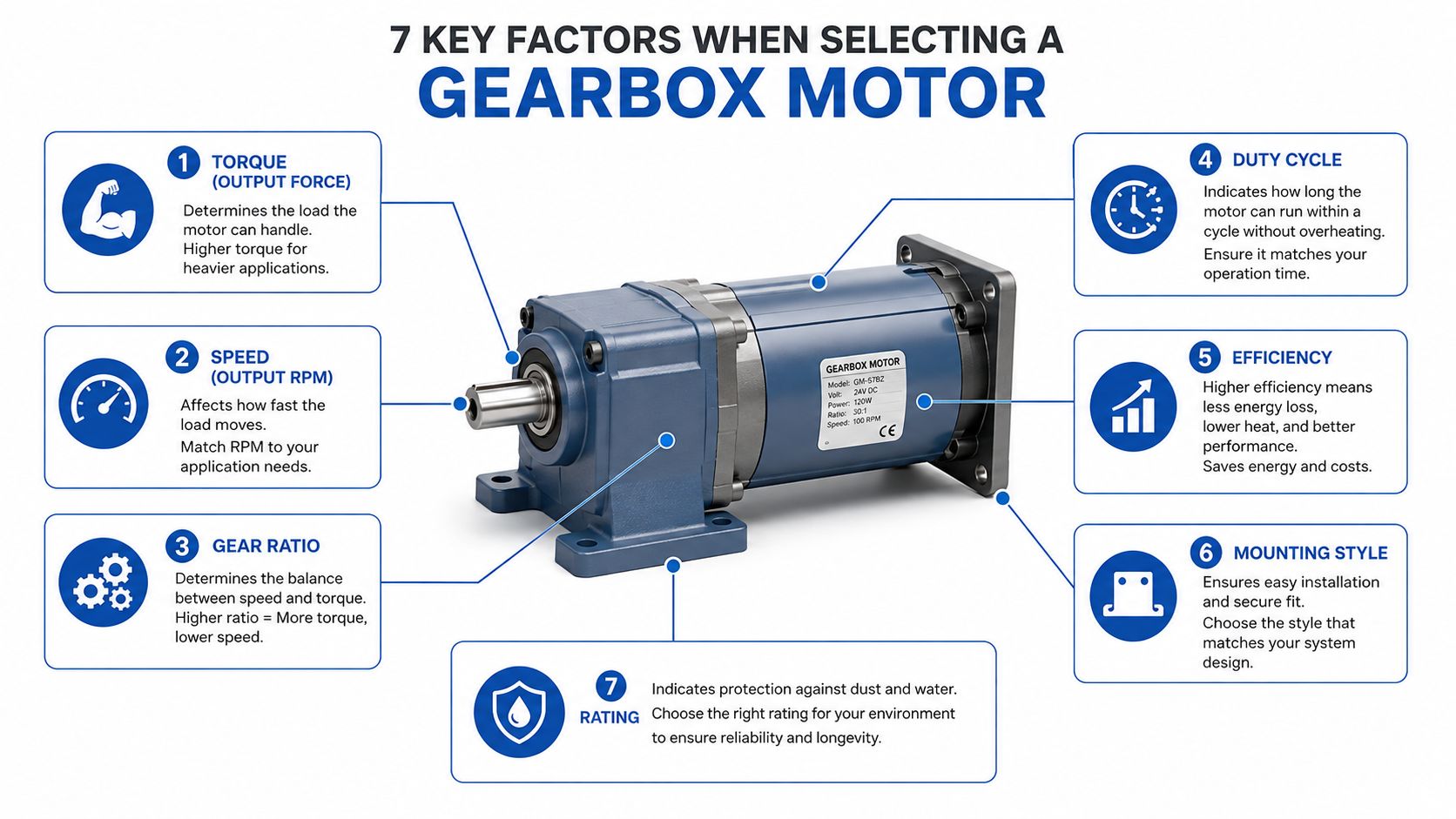
A catalogue search becomes useful only after the driven machine has been described properly. The following seven specifications interact, so changing one can alter the others.
Torque
Torque is the turning force available at the output shaft. Size it against the worst credible load, not the average running condition. Include starting resistance, acceleration, product build-up, shock loading and any risk of the driven machine stalling.
Speed
Output speed is the speed the machine receives after reduction. It isn't the motor's nameplate speed. A motor can run correctly while the machine still runs too quickly if the ratio is wrong.
Ratio
The ratio connects input speed to output speed and contributes to torque multiplication. UK supplier data shows a helical geared-motor range spanning motor powers from 0.12 kW to 200 kW, reduction ratios from 3.77:1 to 28,171:1, and output torque from 87 Nm to 18,000 Nm. This UK helical geared-motor range shows why engineers must select from the load profile rather than from motor power alone.
Efficiency
Efficiency is both an energy figure and a heat figure. Power lost in the motor and gearbox becomes heat, which influences oil temperature, bearing life, enclosure cooling and operating cost. The efficiency curve at the actual duty point matters more than a headline value at an unrelated operating condition.
Duty cycle
Duty cycle describes how the unit works over time. Continuous running, intermittent operation, frequent starts, reversing and repeated acceleration all produce different thermal and mechanical demands. Ratings such as S1, S3 and S5 only become meaningful when matched to the actual shift pattern and control sequence.
IP rating
The enclosure must suit the environment. Washdown, airborne dust, outdoor exposure, mud and hydraulic contamination each demand a deliberate ingress-protection decision. An enclosure that suits a clean indoor panel may not suit a mobile machine exposed to water and debris.
Mounting
Foot, flange, hollow-shaft and solid-shaft arrangements must match the driven machine. Mounting errors are especially expensive because they often appear late, after the frame, coupling or guard has already been designed.
Practical rule: Treat torque, ratio, efficiency and duty cycle as one calculation. A correct nameplate power figure can't rescue a gearbox motor with inadequate thermal capacity or the wrong output arrangement.
A Practical Method for Sizing a Gearbox Motor
Start with the machine, not the supplier's product filter. Write down the required output speed, continuous torque, peak torque, acceleration time, start-stop pattern, direction changes, operating hours and shock-load history. If the machine drives through a chain, belt, coupling or pinion, record the radial and axial loads that reach the gearbox shaft.
Build the load picture
Separate the load into three conditions:
- Continuous running: the torque and speed needed once the machine is moving.
- Starting and acceleration: the extra torque needed to overcome static resistance and accelerate rotating mass.
- Abnormal or shock loading: jams, impact, product accumulation or sudden changes in resistance.
Output power can be estimated from torque multiplied by rotational speed. The gearbox efficiency must then be considered to estimate the motor power required. This is an approximation, not a substitute for checking the manufacturer's torque, thermal and starting curves.
A detailed motor sizing guide can help structure the calculation. Keep a written record of every assumption, including the selected service factor and the reason it reflects the actual duty.
Check the complete arrangement
Choose the output speed required by the machine, then select a reduction ratio that keeps the motor operating in a suitable range. A very high ratio may provide the required torque, but it can also increase sensitivity to lubrication, mounting, service factor and duty-cycle errors.
Avoid two familiar mistakes. Selecting only by motor power ignores acceleration and shock, while adding an arbitrary safety margin can produce unnecessary inertia, cost and poor control response. Before releasing the selection, verify:
- Brake requirement: Confirm whether the load can back-drive or coast.
- Shaft loading: Check belt, chain, coupling, radial and axial forces.
- Thermal capacity: Match heat rejection to the actual operating pattern.
- Electrical details: Confirm voltage, frequency, protection and control method.
- Mechanical fit: Check mounting, shaft diameter, keyway, flange and guarding.
- Environmental suitability: Confirm enclosure protection and ambient conditions.
A credible selection shows the calculation path, duty assumptions, applied factor and fallback limits. It shouldn't be just a final kW figure copied from a catalogue.
How the Same Motor Plays Out Across Applications
Gearbox motors behave differently according to the machine they drive. A unit that performs reliably on a fixed conveyor may struggle on mobile plant because shock, contamination and restricted space change the duty.
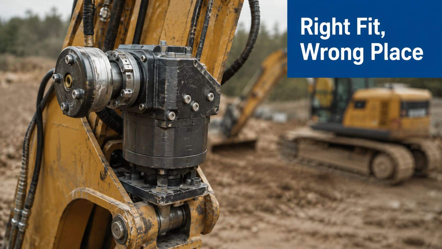
Mobile plant
An excavator attachment or agricultural machine may see impact loads, dirty oil and limited installation space. A practical reference case is an S3 25% duty with IP68 protection and an ISO 4406 cleanliness code specified for the hydraulic fluid. That combination points to a motor selected for intermittent operation and contamination control, rather than one chosen from nameplate power alone.
Low mass, compact packaging and reliable starting can outweigh peak efficiency. A worm arrangement may suit a slower, lighter-duty mechanism, while helical or planetary gearing can provide higher efficiency and compact torque where the duty is harsher.
Materials handling
A conveyor can run for long periods, with loading peaks as material enters the belt or screw. Repeated starts, thermal build-up and possible back-driving make braking, service factor and predictable gearing important. A helical geared motor may be a sound starting point, provided belt tension, acceleration and mounting loads are checked against the complete drive arrangement.
Industrial automation
An indexing or positioning line depends on low backlash, smooth acceleration and repeatable stopping. Electrical compatibility matters just as much as torque, because the gearbox, motor, drive and controls must behave as one motion system. Excessive backlash can turn an apparently adequate motor into a poor positioning solution.
The selection should therefore follow the driven component's overload, coupling and braking characteristics. Application labels are useful for screening, but duty cycle, efficiency and contamination control decide whether performance lasts.
The following video provides a visual reference for hydraulic gearbox motor applications before you compare a particular unit with your machine's duty.
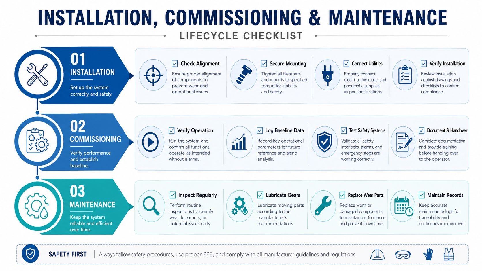
Installation and Maintenance That Extends Life
A gearbox motor can be correctly selected yet fail early on a machine with a misaligned shaft, flexible foundation, contaminated oil or excessive belt tension. Installation and maintenance therefore belong to one reliability process. Nameplate power starts the selection, but duty, efficiency and contamination control determine how well the drive survives in service.
Installation before energising
Inspect the driven shaft, mounting face and foundation for alignment, distortion and adequate support. Before fitting the unit, confirm rotation direction, lubrication level, breather position, electrical protection, enclosure rating and the coupling or pinion arrangement.
A mismatched component should never be forced onto a shaft. Excessive belt or chain tension, heavy chain drives and direct impacts can impose radial loads that damage bearings, even when the motor torque rating appears sufficient. The gearbox may be transmitting the right torque while its bearings carry the wrong load.
Commissioning sets the baseline
Run the unit unloaded for a short period, checking for leaks, abnormal noise and overheating. Raise the load gradually and record current, speed, vibration and oil temperature. These readings provide the maintenance team with a reference for later diagnosis.
Once the equipment has completed its initial operating period, recheck alignment and fasteners. A small change in noise, vibration, temperature or current can reveal a developing problem before visible failure. Record the operating conditions with the readings, since a temperature measured at light load is not comparable with one taken during a demanding duty cycle.
Control contamination deliberately
Contaminated oil degrades faster than clean oil and carries particles through gears, bearings and seals. Use the specified lubricant and clean filling equipment, while keeping water and debris out during storage, filling and servicing. Manufacturer documentation advises renewing hydraulic fluid when water content reaches ≥0.1%. Parker's hydraulic documentation also notes gearbox oil checks every 3,000 hours or 6 months, with some new units requiring oil replacement after 1,000 hours or 1 year.
Treat those intervals as a starting point. Temperature, duty, washdown, dust and moisture should shape the inspection plan. Keep the preventive maintenance checklist alongside the gearbox manufacturer's instructions and condition-monitoring records.
Lubrication protects the teeth, while contamination control protects the lubricant. Both are necessary.
Diagnosing Common Gearbox Motor Faults
Overheating, leakage, escalating noise and premature bearing wear are symptoms. They don't identify the cause by themselves. Replacing the gearbox without checking the load profile, alignment and oil condition often sends the same failure back into service.
Begin with the operating history. Has the machine recently gained a larger pump, heavier product, longer conveyor or different control sequence? A helical unit that ran acceptably before a hydraulic pump retrofit may now be working beyond its thermal or torque envelope, even if the motor nameplate hasn't changed.
Work from evidence
Check the following in order:
- Duty history: Compare actual starts, reversals and running hours with the original selection.
- Temperature: Measure the gearbox and oil temperature under a representative load.
- Lubricant condition: Look for water, particles, incorrect viscosity, foaming or a low level.
- Alignment: Inspect the motor, gearbox and driven shaft together.
- Mounting: Check fasteners, foundation stiffness, shaft support and coupling condition.
- Load profile: Investigate jams, product accumulation, belt tension and unexpected resistance.
A planetary motor grinding on a telehandler may have suffered contamination, shock loading, bearing damage or an incorrect installation. The noise directs attention towards the transmission, but the root cause may sit in the hydraulic circuit, attachment loading or service history.
Match symptom to question
| Symptom | Questions to ask first |
|---|---|
| Rising temperature | Has the duty changed, is the oil correct and can the unit reject heat? |
| Oil leakage | Is the breather positioned correctly, is a seal damaged or is the housing overfilled? |
| New or worsening noise | Has alignment changed, is a bearing loaded incorrectly or are teeth damaged? |
| Premature bearing wear | Are belt, chain, radial and axial loads within limits? |
| Slow or inconsistent output | Is the motor receiving the expected pressure or voltage, and is the gearbox slipping or overloaded? |
| Repeated trip or stall | Did the load increase, has acceleration changed or is the selected ratio unsuitable? |
The diagnostic aim is to restore the operating conditions the gearbox was designed for, then confirm the result through temperature, vibration, current, pressure or speed readings. That approach protects total cost of ownership better than blind component replacement.
Choosing a UK Supplier and Planning Your Next Step
A gearbox motor that fits well on paper but lacks the right mounting, ratio or service support can create avoidable downtime. For UK OEMs and MRO teams, supplier choice should therefore include the operating conditions, maintenance plan and contamination controls, not only the part number and delivery date.
UK buyers commonly work with a distributor, an OEM-direct supplier or a hydraulic-system specialist. A distributor may provide wide catalogue access and stock visibility. An OEM can supply matched units, technical documentation and application-specific parts. A hydraulic specialist is useful when the motor must integrate with an existing pump, valve, filter, manifold or mobile power circuit.
Ask what happens after delivery
Use the first supplier call to establish how the proposed unit will be supported. Ask whether an obsolete motor can be cross-referenced by torque, displacement, ratio, shaft and mounting. Confirm whether the supplier will compare repair, replacement and redesign when the existing unit fails, and whether seals, bearings, couplings and other compatible parts remain available.
Discuss commissioning as well. Can the installation and baseline checks be reviewed? Will the supplier assess hydraulic pressure, flow, duty cycle and contamination exposure? Is the quoted unit physically in stock, or does the stated date depend on another manufacturer? These answers indicate how well the supplier can support the motor through its service life.
UK supply models vary. Geared Motors UK states that it supplies single-phase and three-phase geared motors and offers next-day delivery across the UK mainland for qualifying orders placed before 16:00. A Telford provider describes support covering inspection, commissioning, removal, installation, delivery and collection throughout the UK in its gearbox motor service offering.
A Coventry company operating since 1987 lists planetary, helical, bevel-helical and worm gear reducers and gearmotors. Its gearbox and geared-motor catalogue shows the range of architectures engineers may compare. The duty should determine the gearbox type, because efficiency, heat rejection and contamination tolerance affect long-term performance as much as nameplate power.
Give the supplier a load profile, output speed, continuous and peak torque, duty cycle, ambient conditions, washdown or contamination exposure, fluid cleanliness targets, drawings, shaft loads and mounting details. Include the fault history when replacing a failed unit. MA Hydraulics Ltd supplies hydraulic components, gear motors, gearboxes and bespoke power solutions, and can support sizing, cross-referencing and replacement work for mobile and industrial applications.
A verified selection should leave you with the reason for the ratio, the expected heat behaviour, lubricant and contamination limits, mounting requirements and measurements for confirming healthy operation after commissioning.
MA Hydraulics Ltd can help match gear motors, gearboxes and hydraulic power components to your load, duty cycle, mounting and contamination-control requirements. Phone 01724 279508 today for practical selection or replacement advice, or send MA Hydraulics Ltd a message with your application details.
