
A boom on a mobile machine is refusing to reach its working pressure. The operator says the pump is tired, the maintenance team suspects a relief-valve problem, and the gauge appears to support both conclusions. It reads slightly low, but nobody knows whether the hydraulic circuit is at fault or the instrument is lying.
That situation is common in workshops. A pressure gauge can look clean, respond to pressure and still mislead fault-finding because of drift, hysteresis, vibration damage or a previous pressure spike. Hydraulic pressure gauge calibration turns that uncertainty into a recorded comparison against a traceable reference, giving engineers evidence they can use before replacing a pump or dismantling a valve.
Why Hydraulic Pressure Gauge Calibration Deserves More Attention
A maintenance team can lose valuable production time by trusting a gauge that is only apparently healthy. On a mobile boom, a reading that is modestly below the true system pressure may send engineers towards the pump, even when the pump is delivering correctly. They may adjust the relief valve, inspect hoses and change components before checking the instrument that started the investigation.
That isn't a criticism of the engineers. Working gauges are exposed to vibration, contamination, pressure cycling, thermal changes and occasional overloads. A pointer can return to zero and move smoothly enough for an operator's daily checks while the instrument has developed a meaningful error elsewhere on the scale.
Practical rule: A gauge that looks fine has passed a visual inspection. It hasn't necessarily passed a calibration.
Calibration is a diagnostic control
Proper calibration compares the gauge indication with a reference at defined pressure points. The technician records the reference value, the gauge reading and the direction of travel, then checks whether the result remains within the gauge's stated tolerance. That process identifies errors which a single pressure check won't show, particularly hysteresis and non-linearity.
The result is useful in three ways:
- Fault-finding: You can separate an instrument error from a genuine pump, valve or actuator problem.
- Quality records: A controlled calibration record supports an auditable measurement process and complements the traceability expectations found in UK specifications.
- Asset protection: Early evidence of drift or overload lets you adjust, repair or replace the gauge before it misdirects a larger investigation.
A UK government specification for differential pressure gauges requires a valid certificate from a test house able to demonstrate traceability to national standards. The principle applies well to hydraulic measurement too. A certificate isn't valuable because it has a stamp on it. It's valuable because it identifies what was tested, against which reference, at which points and with what uncertainty. See the UK government specification for traceable gauge certification for the kind of documentation requirement engineers may encounter.
Trust the measurement, not just the dial
The important question isn't whether a gauge is technically within tolerance at one point. Ask whether its error is acceptable for the decision you're making. A gauge can pass a broad industrial class yet still be too imprecise for diagnosing a high-pressure fault where a small difference changes the conclusion.
That is why calibration belongs in the diagnostic process, not at the end of an annual compliance checklist. It gives the maintenance team a defensible basis for deciding whether to keep investigating the hydraulic circuit or investigate the gauge itself.
Equipment You Need on a UK Calibration Bench
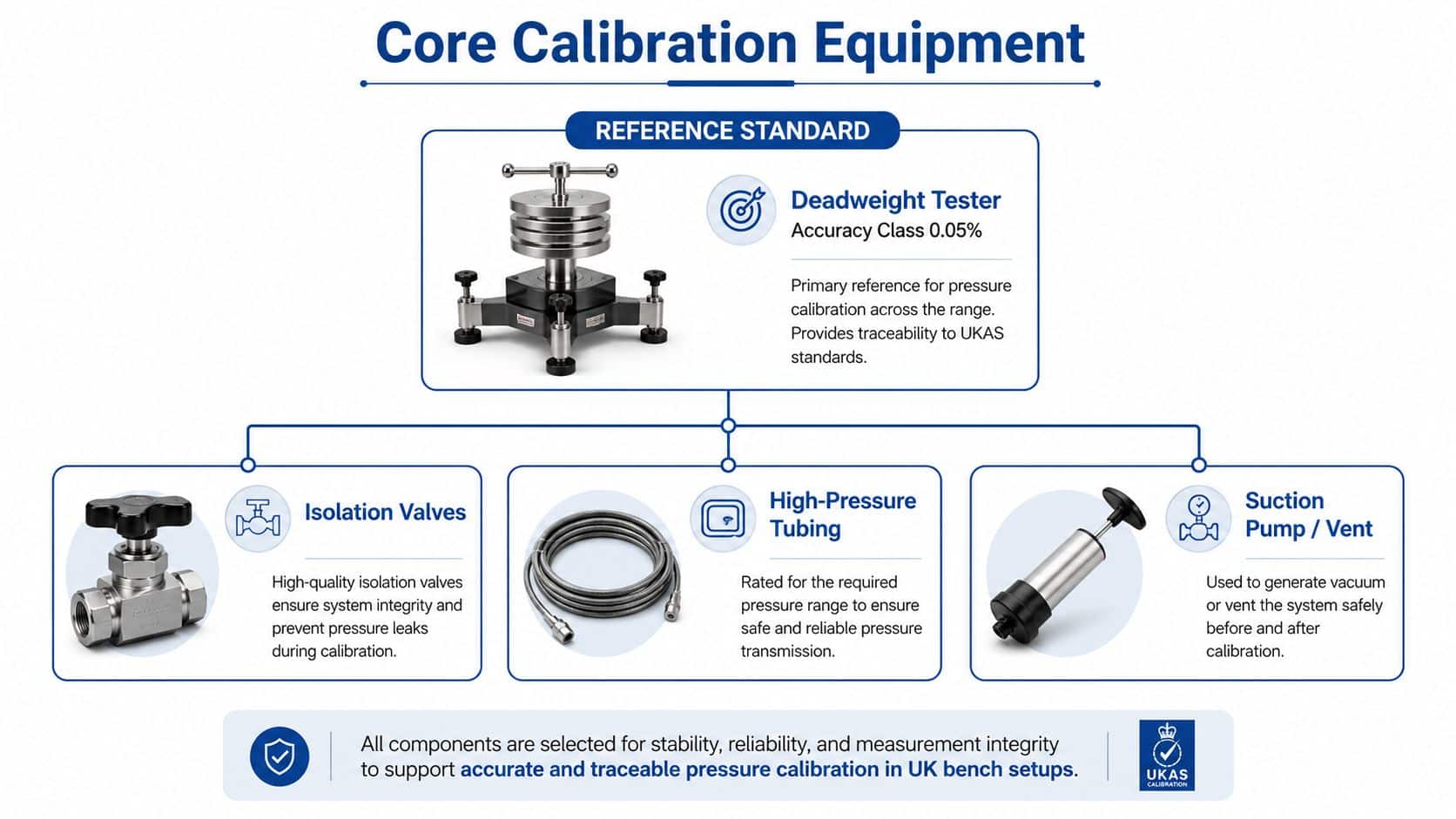
A reliable bench starts with the reference standard, not the gauge under test. For the highest accuracy work, a deadweight tester or pressure balance generates pressure from a known piston area and calibrated masses. NPL describes a UKAS-accredited service for oil-operated pressure balances covering 500 kPa to 200 MPa, with an uncertainty of 0.0031% + 0.24 ppm/MPa, and states a calibration accuracy of ± 5 Pa for its pressure balance service. Those figures establish the strength of the UK traceability chain, although an in-house workshop will normally use a calibrated secondary reference rather than operate a national-level standard. Details are available from NPL's pressure and barometry service.
A digital pressure calibrator is often more convenient for routine workshop checks. It gives a direct reading, can be portable and works well when the reference has a suitable range and current traceable certificate. The reference must be materially better than the gauge being tested. A second general-purpose gauge isn't a dependable standard just because it appears newer.
Build the pressure path around the work
The bench needs more than a reference instrument. Prepare:
- High-pressure tubing and hoses: Select assemblies rated for the maximum test pressure, with suitable safety margins and secure end connections.
- Isolation valves: Use valves that shut cleanly and let you isolate the gauge without disturbing the reference.
- Pump and vent arrangement: A hand pump, suction pump or other suitable pressure source should allow controlled pressure generation and safe release.
- Adapters: Keep clean BSP, NPT and metric adapters available, but don't force incompatible threads together. An adapter that restricts flow or traps air can make the pressure settle slowly and complicate readings.
- Fluid management: Use a compatible hydraulic oil or water circuit, depending on the gauge, reference and bench design. Clean fluid matters because contamination can damage valves and affect repeatability.
- Mounting and drainage: Fix the gauge and reference so the dials are readable, keep the bench stable and provide a controlled way to collect or remove test fluid.
For a compact workshop setup, a hydraulic pressure tester kit can provide a starting point for connecting test equipment, provided its pressure rating, fittings and reference capability suit the gauges in your programme.
What an accredited laboratory adds
A UKAS laboratory must demonstrate competence, defined capability and controlled measurement uncertainty. UKAS schedules list hydraulic gauge work from 500 kPa to 5.5 MPa and 5 MPa to 110 MPa, with expanded uncertainties of 0.039% and 0.030% respectively. A separate schedule covers pressure-balance and associated hydraulic work from 0.5 MPa to 7 MPa, 7 MPa to 140 MPa and 140 MPa to 500 MPa, with expanded uncertainties of 0.0040%, 0.0053% and 0.011%. These ranges show why you should match the laboratory capability to the gauge range rather than assume every certificate offers the same measurement quality. The relevant UKAS calibration schedule sets out the capability in measurable terms.
Preparing the Gauge and the Test Circuit Safely
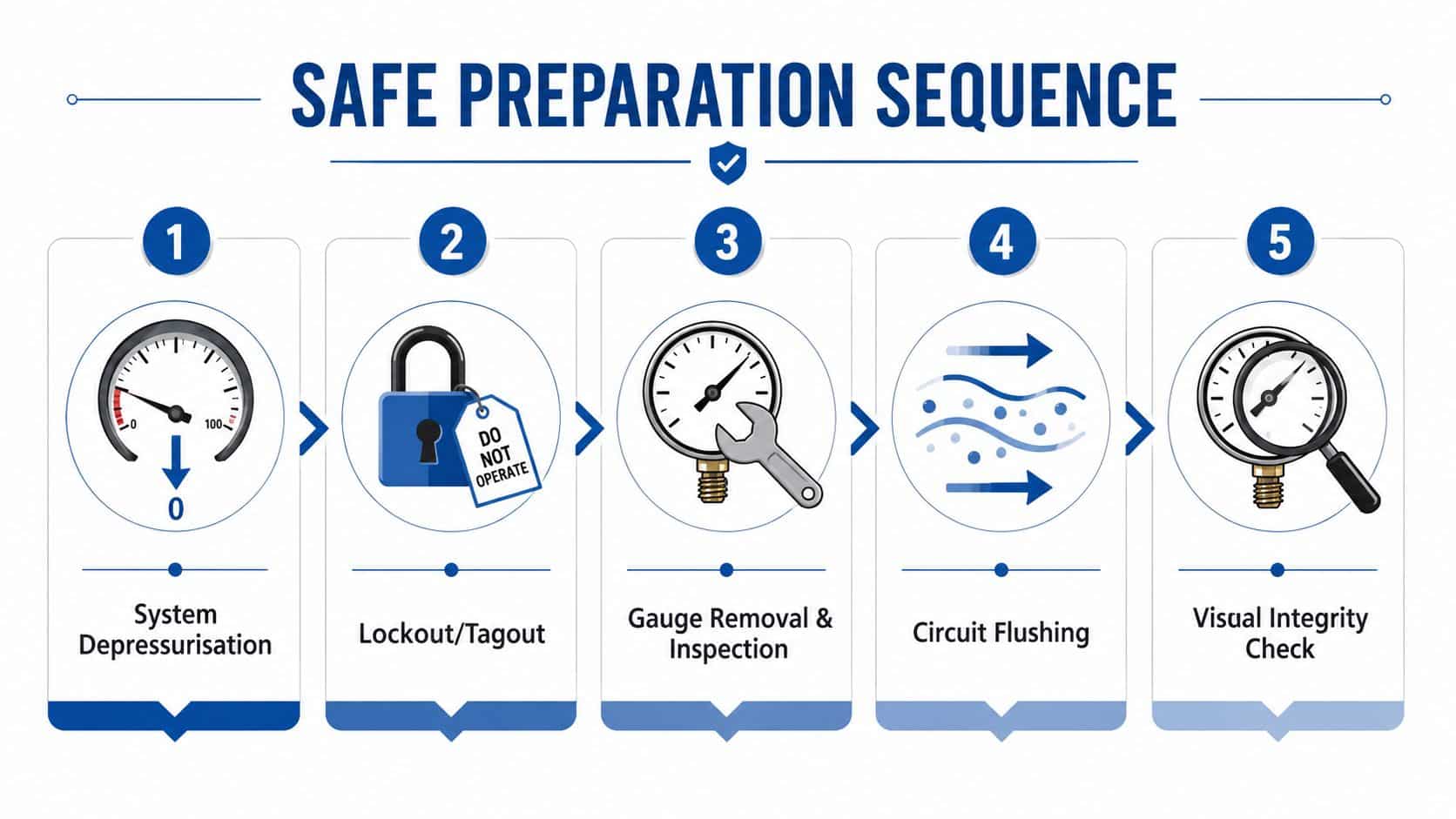
A gauge can be within tolerance and still mislead fault-finding if the test circuit is not prepared properly. Before applying pressure, isolate the gauge or circuit, lock out the energy source where the equipment procedure requires it, and prove the pressure has fallen to atmosphere. A machine display or the gauge under test cannot prove depressurisation.
Inspect the instrument before fitting it to the bench. Check for a cracked window, bent pointer, damaged case, loose connection, blocked port, fluid ingress or overload marks. Confirm the identification plate, range, units, connection type and asset number. If the gauge came off dirty mobile plant, cap the port and keep contamination out. Guidance on selecting and identifying a suitable hydraulic pressure gauge can help when the instrument details are unclear.
Prepare people and connections
Wear eye protection as a minimum, with gloves and site PPE suited to the hydraulic fluid and equipment. A pinhole leak can inject oil through skin, so stand clear of connections during the first pressure application. Use rated hoses, adaptors and valves, and confirm how pressure will be relieved before starting the pump.
Cleanliness affects repeatability as well as component life. Clean or flush the circuit as appropriate, remove trapped air and check connections for leaks at low pressure before increasing the load. Air compresses and expands, producing unstable readings or a delayed response that can be mistaken for gauge hysteresis.
Condition the mechanism
UK guidance recommends cycling the instrument to its upper limit at least twice, holding there for one minute, then checking indications at 0%, 50% and 100% of span. The pressure gauge calibration guidance from SM Gauge describes this conditioning and checking approach.
Complete the cycles before recording formal results. Controlled pressure changes can expose a sticking pointer, overload damage or a zero that fails to return. That matters on high-pressure mobile and industrial systems, where a small response problem can send fault-finding towards the wrong valve or pump. Stop if the gauge behaves abnormally and record the observation. More pressure will not repair a damaged movement.
Running the Calibration Sequence Step by Step
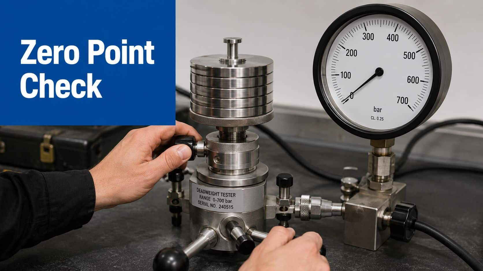
Start with the gauge vented to atmosphere. Allow the pointer or digital display to settle, then record the reference zero and the indication from the gauge under test. If the pointer doesn't return cleanly, note the zero error before making any adjustment.
Use rising and falling pressure
Apply pressure in ascending steps across the span. A practical high-pressure method uses six pressure points, followed by three repeat measurements at 50% full scale, as described by Rhopoint Metrology's hydraulic pressure calibration service. Record both the reference and test readings at each point, along with the direction of travel and any settling behaviour.
For a gauge covering 0 to 400 bar, an example sequence would be:
| Test point | Target pressure |
|---|---|
| Zero | 0 bar |
| Point 1 | 80 bar |
| Point 2 | 160 bar |
| Point 3 | 240 bar |
| Point 4 | 320 bar |
| Full scale | 400 bar |
These are test points for the example, not a universal requirement. If the dial graduations don't line up with a target, read the pointer consistently and record the actual reference pressure. Don't force the result to a convenient printed mark.
After the ascending pass, reduce pressure through the same points. The difference between the rising and falling readings is evidence of hysteresis. A single ascending check can miss that error, just as a zero check alone can miss non-linearity near the top of the range.
Adjust only when the instrument allows it
Some gauges have external zero or span adjusters. If the manufacturer permits adjustment, correct the zero first, repeat the conditioning cycle and then check span. Adjustments can interact, so confirm the full sequence again rather than assuming one turn has fixed the instrument.
A sealed or non-adjustable gauge should be treated differently. Record the error at each point and provide correction factors only if your quality system allows the gauge to remain in service with those corrections. If the error is unstable, excessive or inconsistent between rising and falling pressure, declare the instrument unsuitable for the task and assess repair or replacement.
The calibration video provides a visual reference for the type of bench activity involved.
Understanding Tolerances and Measurement Uncertainty
A calibration certificate usually contains two separate ideas. Tolerance is the permitted error for the gauge or application. Measurement uncertainty describes the doubt associated with the calibration result, including the reference, method and conditions. A gauge can be within its tolerance while the measurement process still needs careful interpretation.
EN 837-1-linked UK practice commonly uses accuracy classes from ±0.1% to ±4% of span. The correct class depends on the decision the gauge supports. A rugged mobile-plant indication may not need the same performance as a test-rig reference, but a fault-finding gauge used to distinguish between close pressure conditions deserves more scrutiny than a simple operator display.
| Class | Tolerance of span | Typical use |
|---|---|---|
| ±0.1% | ±0.1% | Precision test and reference work |
| ±0.25% | ±0.25% | Controlled test benches |
| ±0.5% | ±0.5% | Higher-accuracy diagnostic measurement |
| ±1% | ±1% | General process and industrial indication |
| ±2% | ±2% | General hydraulic service work |
| ±4% | ±4% | Rugged, lower-precision indication |
The class range and practical benchmark are set out in UK guidance on pressure gauge calibration tolerances. Treat the table as a selection aid, then check the actual manufacturer's specification and the consequence of an incorrect decision.
Read the result at the working pressure
Percentage of span can hide the size of the error at a particular pressure. For example, a 0.5% of span gauge covering 0 to 400 bar has a permitted error of 2 bar if that class is applied across the full span. At a diagnostic point of 350 bar, that difference may be enough to send an engineer towards the wrong relief-valve or pump conclusion, even though the gauge remains technically within its stated class.
That doesn't make the gauge defective. It means the gauge class and the diagnostic task may not match. A higher-class reference or a calibrated digital instrument can provide a clearer answer, while the working gauge may remain suitable for routine indication.
Understand expanded uncertainty
UKAS schedules commonly express expanded measurement uncertainty with k=2. The coverage factor indicates how the uncertainty has been expanded for reporting. Don't compare a gauge's accuracy percentage with a laboratory's uncertainty percentage as if they were interchangeable. Check the pressure range, units, coverage factor and whether the uncertainty is appropriate to the result you need to defend.
A UKAS-accredited capability lists 300 ppm across 1.0 to 413.7 MPa for hydraulic pressure gauge work, with expanded uncertainty identified as k=2, as shown in this UKAS calibration schedule. At the high end, ask for the actual uncertainty associated with the test point and decide whether the gauge's remaining error matters to the troubleshooting decision.
For system-level decisions, a pressure monitoring systems guide can help frame the relationship between the indicated reading, the reference reading and the record of zero, span and calibration date.
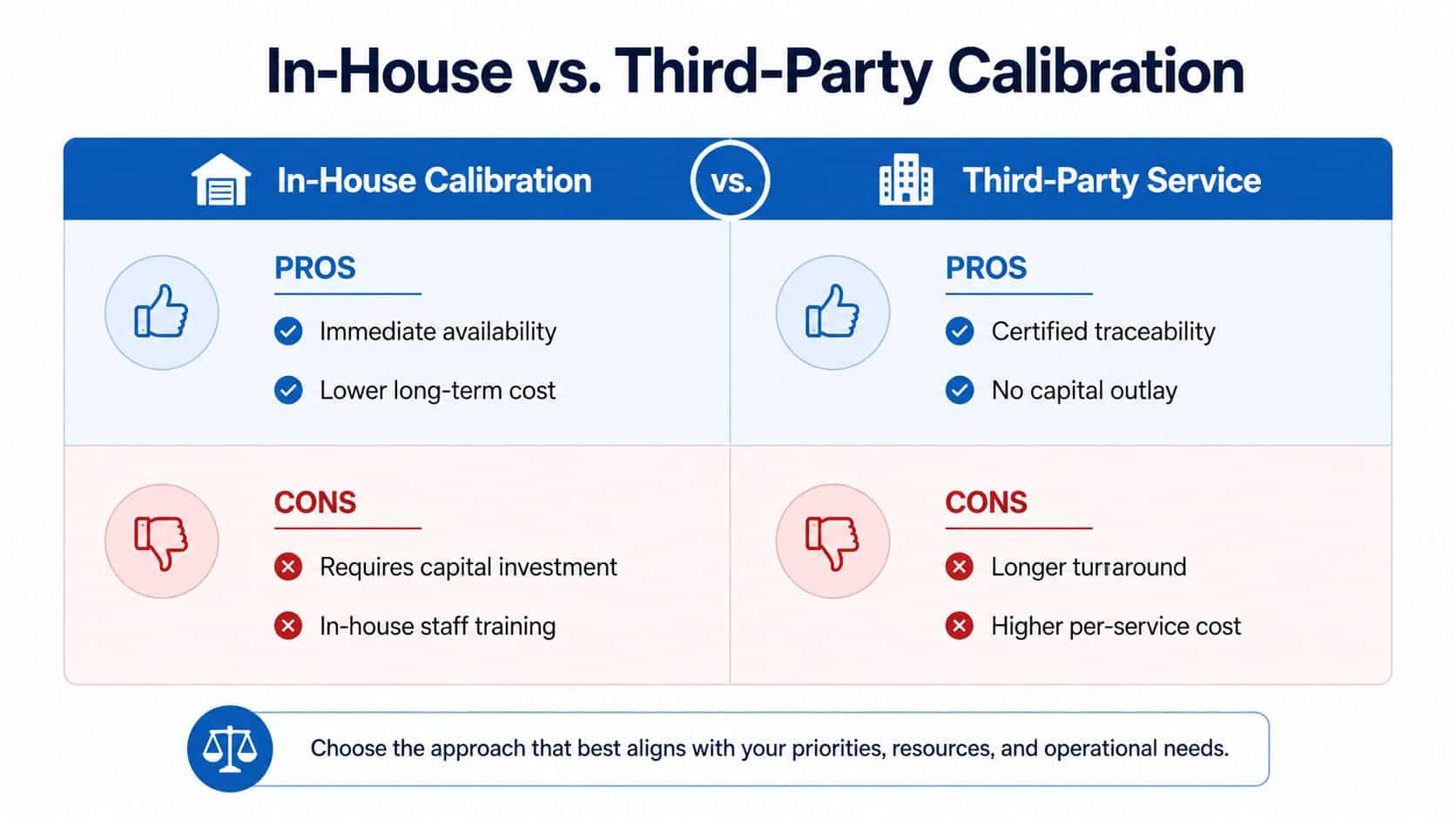
Choosing Between In-House and Third-Party Calibration
In-house checks suit teams that need quick answers and have suitable equipment, trained staff and a controlled method. A calibrated pressure reference and a sound test circuit can expose a drifting gauge before a maintenance decision is made. The limitation is traceability. Your workshop record is only as defensible as the reference certificate, procedure, environmental control and competence behind it.
Third-party UKAS-accredited calibration is the stronger route when a customer, quality system or safety case requires formal traceability. It also removes the need to maintain every part of the calibration capability internally. The trade-off is time away from service, transport, administration and the provider's charge per instrument.
Make the decision by risk
Use an internal check when you need an interim condition check, the gauge is non-critical and the reference has adequate traceability. Use a third-party laboratory when the gauge supports a regulated or customer-controlled process, when a formal certificate is required, or when the gauge's uncertainty is important to the decision.
A practical MRO rule is to separate screening from certification. Screen gauges in-house after suspicious readings, overloads or repairs. Send selected instruments for formal calibration according to their criticality and your documented quality requirements. That approach avoids sending every gauge away while preserving independent evidence where it matters.
On-site calibration can make sense for installed gauges that are difficult or costly to remove. It reduces removal and refitting work, but the provider must control the test conditions and explain how the site setup affects uncertainty. A laboratory normally offers better environmental control, while on-site work can reduce equipment downtime.
Turnaround needs planning. One UK service quotes 7 to 14 working days for pressure gauge calibration, so don't wait until a planned shutdown has started. The Rhopoint pressure calibration service also recommends formal calibration at least once a year, with interim in-house checks based on usage.
Scheduling, Records and Common Faults to Watch For
An annual interval is a sensible starting point, but mobile plant and high-pressure systems often need a more deliberate schedule. Set the interval around usage, vibration, pressure cycling, fluid conditions, gauge criticality and the consequence of a misleading reading. Bring calibration forward after an overload, pressure spike, pump rebuild, valve incident, unexplained process result or physical impact.
A record should let another engineer reconstruct the test without relying on memory:
- Instrument identity: Record the asset number, range, units, manufacturer and connection.
- Reference details: Note the reference standard, certificate identity and traceability status.
- Test method: Record the fluid, test points, rising and falling readings, repeat checks and any conditioning cycle.
- Conditions: Include relevant temperature, cleanliness observations and abnormal behaviour.
- Decision: State the tolerance used, uncertainty considered, pass or fail result, adjustment or correction factor.
- Approval: Add the technician's sign-off, date and next-due date.
Treat faults as evidence
A sticking pointer can indicate a damaged movement or contamination. Hysteresis points towards mechanical stress, friction or Bourdon-tube damage. A zero shift after a pressure spike may show overload. Slow response can result from trapped air, a restriction, viscosity effects or a deteriorating mechanism. Fluid behind the dial needs investigation before the gauge returns to service.
A gauge can pass a tolerance check and still mislead fault-finding if it sticks, responds slowly or behaves differently on rising and falling pressure. Record the full ascending and descending sequence before adjusting anything. If the error is repeatable and the design allows adjustment, correct it and retest. An unstable result or mechanical damage usually supports replacement more strongly than repeated adjustment.
Send instruments to a laboratory properly
Clean the outside, cap the connection, identify the fault or service history, and provide the required range and accuracy information. State whether you need UKAS calibration, a traceable certificate or a condition report. Package the gauge so the pointer, window and connection cannot be damaged in transit.
Keep a trusted spare for critical diagnostic work. A controlled spare provides a known comparison when the installed gauge is removed, preventing calibration work from stopping fault-finding across the plant. Give it its own controlled record. Storage in a cabinet does not prove that it remains accurate.
MA Hydraulics Ltd can help identify suitable pressure monitoring and hydraulic components for mobile and industrial systems, including practical support when a gauge reading needs checking against the wider circuit. Visit MA Hydraulics Ltd, phone 01724 279508 today, or send us a message with your application details.
