
A maintenance engineer in a cold yard doesn't need a lecture on valve theory at 7 a.m., they need the right part in their hand before the machine sits idle another hour. That's where the 3 way ball valve earns its keep, because one compact body can divert, mix, or isolate flow without forcing you to build the circuit out of several separate valves.
The confusion usually starts when people think of ball valves as simple open-or-shut devices. A 3-way version is different, because the internal passage decides which ports connect, and that choice changes how the whole circuit behaves. Get that right, and you simplify routing, reduce clutter, and make maintenance easier. Get it wrong, and you can end up with dead legs, poor shut-off, or a valve that looks right on paper but behaves badly in service.
What a 3 Way Ball Valve Actually Does
A 3 way ball valve has three ports and is used to divert or mix flow paths, with the ball's drilled passage determining whether the valve behaves as an L-port or T-port design. That basic idea matters because the body itself doesn't tell you enough. Two valves can look almost identical from the outside and still perform very differently once they're in a circuit.
The simplest way to picture it
Think of it as a compact junction block with a rotating internal plug. Instead of two separate valves and extra pipework, you've got one body that can steer fluid from one path to another, or bring two paths together if the bore is drilled for that duty. That's why these valves show up in mobile hydraulics, process skids, and service circuits where space is tight and the routing needs to stay clean.
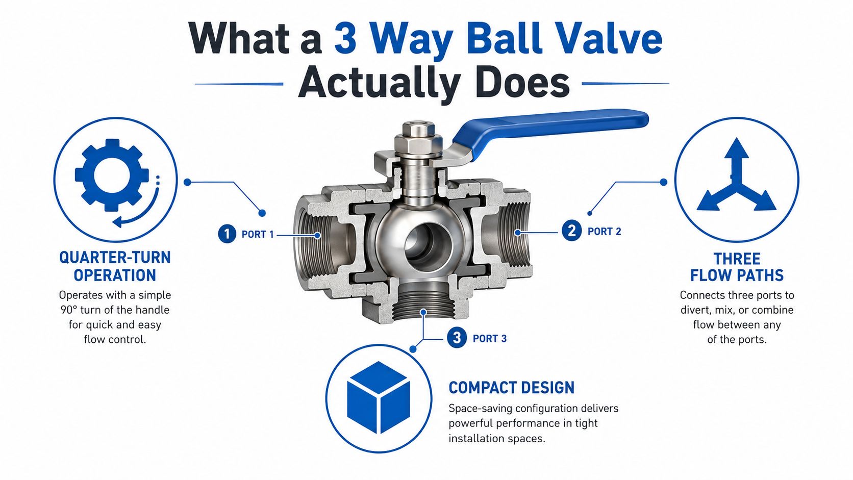
The useful mental model is simple. A standard two-port ball valve is a gate. A three-port valve is a selector. In practice, that means the same component can help you choose between two lines, merge flows, or isolate a branch without adding another valve body and another set of threaded joints to leak later.
Practical rule: if the circuit needs one common line to connect with two alternates, a 3-way valve is often the first component worth sketching.
For UK buyers reading catalogues, the important part is not the name, it's the port pattern. If you can identify the common port and the two alternates on the schematic, you're already halfway to the right selection. The rest is matching the internal bore to the job.
Inside the Ball and How Flow Moves
A three-way ball valve acts as a compact junction block with a rotating internal plug. Instead of two separate valves and extra pipework, one body can steer fluid from one path to another, or bring two paths together if the bore is drilled for that duty. That is why these valves appear in mobile hydraulics, process skids, and service circuits where space is tight and the pipework has to stay tidy.
Three-way ball valves are commonly described as quarter-turn valves because the internal ball rotates 90 degrees to change the flow path. Some product literature also shows 90-degree diverter and 180-degree switching variants. That tells you two things straight away. The movement is fast, and the routing is set by how the ball is drilled, not by the handle shape alone.
Why the bore shape matters
Inside the body, the ball is not a solid sphere with a hole through it. It is drilled with either an L-shaped or T-shaped passage. When the handle or actuator turns, that passage lines up with the ports in different ways. In an L-port, the passage behaves like a selector between two paths. In a T-port, the geometry can link, split, or mix paths depending on the port orientation and the valve's stop arrangement.
That is the reason the valve can feel deceptively simple from the outside. What matters is not just whether it turns, but which port is common and which ports connect in each position. A junior engineer who learns to read that internal layout will avoid a lot of expensive trial and error on site.
A useful analogy
The ball works like a railway turntable inside a pipe. The body stays still, but the internal route changes direction when the ball rotates. The seats around the ball keep the media where it belongs, and the bore decides which track the flow takes. That is a better way to visualise the valve than treating it as a slightly more complicated two-way ball valve.
The key selection habit is to stop asking, “Is it open or closed?” and start asking, “Which ports connect in this position, and what happens to the third port?” That one shift in thinking is what separates a quick replacement from a correct one.
L-Port Versus T-Port in Real Circuits
An L-port valve diverts flow between two paths. A T-port valve can link, split, or mix three paths, and not every T-port arrangement gives full shut-off in every direction. That distinction matters in the circuit, where the question is not what the handle looks like, but whether the valve gives you isolation, bypass, mixing, or a clean changeover without leaving a problem behind.
Where L-port earns its place
An L-port valve is the straightforward diverter. It suits a line that needs to go to one of two destinations, or a setup where two sources must feed a common line one at a time. In a hydraulic cooler bypass, for example, it can send flow through the cooler or around it. In a tank return selector, it can direct return oil to one reservoir or another without forcing the fitter to install a second valve.
That is why an L-port often feels familiar on site. The circuit behaves like a fork in the pipework, one route is active, the other is left out of service, and the valve's job is to make that choice reliably.
Where T-port makes more sense
A T-port valve gives you more options, but those options come with conditions. It can support mixing or distribution duties, which makes it useful in blending loops or circuits where one feed needs to be shared across two branches. In practice, that extra flexibility only helps if the internal porting matches the job, so the manufacturer's flow diagram matters more than a guess based on the handle position.
Some T-port valves can't fully isolate all three ports at once, and that surprises people who assumed “three-way” meant “all directions, always”.
Dead-leg risk is the other point people miss. If a section of bore traps fluid between positions, that trapped volume can stagnate. In clean process service, that may be a nuisance. In dirty hydraulic service, it can become a maintenance headache because contamination sits where you can't flush it easily.
The same selection habit applies to a 3-way diverter valve, match the port pattern to the actual circuit outcome. A wrong shorthand in a quote sheet can hide the fact that one valve diverts and another mixes.
Selection Criteria Engineers Use
The fastest way to choose badly is to size by pipe diameter alone. Start with what the valve must do in the circuit, then check whether the pressure and temperature envelope supports that duty, whether the passage can pass the required flow without creating avoidable resistance, whether the end connections fit the installation, and whether the fluid will suit the materials. A proper quote review should read like a specification check, not a part-number hunt.
A useful way to judge a 3 way ball valve is to ask a practical question first. Is the valve isolating one branch, bypassing flow, or mixing two streams into one? That answer tells you more than the body size on its own, because port geometry, sealing behaviour, and dead-leg risk all change what the valve really does in service.
Start with the pressure and temperature envelope
A UK supplier datasheet for a PN30 brass 3-way ball valve shows a size-dependent working limit of 30 bar at 1/4 to 3/4 inch, dropping to 20 bar at 1 to 1 1/4 inch and 16 bar at 1 1/2 to 2 inch, with a working temperature range of -20°C to +120°C. The lesson is straightforward. Larger bodies do not automatically keep the same rating as smaller ones, because sealing load and body stress change as section size increases. If the line size grows, re-check the rating instead of assuming the original pressure class still applies. Typical Working Pressure by Bore Size on a PN30 Brass Body
Then match flow, not just thread size
A valve can fit the pipe and still be wrong for the duty. You want the effective flow capacity to suit the circuit, otherwise the system sees unnecessary pressure loss or sluggish switching. Internal passage shape matters here more than the outside dimensions. A compact body with the wrong bore arrangement can behave like a narrow section of pipe, even if the connection size looks correct on paper.
If you are comparing families of valves, a quick review of common hydraulic valve families helps keep the discussion tied to circuit function instead of catalogue wording. That matters because a quote sheet may describe the valve by connection size while the circuit needs a diverter, a selector, or a mixing duty.
Check materials and mounting last, not first
Body material, seat material, and end connection style should come after the duty check. Brass is common in general service, while more demanding fluids may call for stainless or other body materials. Seals and seats need to suit the media and temperature cycling, and the mounting style has to match the installation, whether that is threaded or flanged. If the fluid is mineral oil, water-glycol, or a bio-fluid, ask for compatibility data instead of assuming one seat material covers everything.
The order matters because the wrong material choice can look acceptable at quotation stage and still fail the job later. A valve that is fine for one fluid may age quickly in another, especially where temperature swings and repeated cycling are part of the duty.
| Typical Working Pressure by Bore Size (PN30 Brass Body) | ||
|---|---|---|
| Bore Size | Maximum Working Pressure | Working Temperature Range |
| 1/4 inch to 3/4 inch | 30 bar | -20°C to +120°C |
| 1 inch to 1 1/4 inch | 20 bar | -20°C to +120°C |
| 1 1/2 inch to 2 inch | 16 bar | -20°C to +120°C |
A good buying habit is to ask one question before comparing prices, “What does this valve need to do in the circuit?” That single question usually rules out half the catalogue.
Manual Versus Actuated Operation
The cheapest valve on the page isn't always the cheapest valve in service. If the valve is awkward to reach, needs repeatable positioning, or forms part of a control scheme, then actuation becomes part of the selection, not an optional extra. The trick is to pay for movement only where movement matters.
Four common operating options
- Manual lever: Best when an operator is present and the valve moves infrequently. It's simple, direct, and easy to understand, but it gives no position feedback.
- Gear operator: Useful when torque is higher or the installation leaves little room for a long lever. It adds control in a compact package, which can help on larger bodies.
- Electric actuator: Suits remote control and automation, especially where a PLC or timed sequence needs consistent positioning. It's clean to integrate, but wiring and controls have to be planned properly.
- Pneumatic actuator: A strong fit for high-cycle duty and fail-safe arrangements, provided the site has compressed air available.
A Siemens 599 Series three-way ball valve technical instruction specifies an ANSI 250/600 WOG rating and notes that the valve provides a slowly opening valve. That detail matters because actuation speed affects how the circuit behaves, especially when you're trying to avoid sudden flow changes. Siemens 599 Series 3-Way Ball Valves Technical Instruction
Where the choice changes the job
A lever makes sense on a tank return selector that's moved once a day. An electric actuator makes sense on a bypass that the control room needs to switch remotely. Pneumatic actuation earns its keep on a line that cycles often and needs fast, consistent movement. The cost step-up is real, but so is the difference between a quick adjustment and a valve that's effectively inaccessible during a fault.
If you're comparing a valve to a solenoid-style alternative for a compact control function, keep the application clear in your head. A 3-way ball valve is a rotating isolation and routing device, not a drop-in answer to every control problem, and the actuator style changes the maintenance burden as much as the purchase price. For that reason, it's worth reviewing options like a 3-way solenoid valve only after you've defined the duty, access, and feedback you need.
Where 3 Way Ball Valves Earn Their Place
A 3-way ball valve earns its keep where the circuit needs a real routing choice. That can be a tractor loader with a bypass function, a materials-handling machine that needs to switch between two actuator paths, or a process skid that mixes two streams into one controlled line. The valve is valuable because it replaces complexity with one clean decision point.
Mobile and agricultural hydraulics
On agricultural machinery, the valve often acts as a selector or diverter. That suits routines where one pump source has to serve different functions at different times, or where a bypass path needs to open without disturbing the whole system. In mobile plant, the practical advantage is easy routing and fewer fittings, which matters when the machine lives in mud, vibration, and awkward access.
Industrial skids and maintenance work
In factory and skid-mounted systems, a T-port valve can help with blending or distribution. If the process needs flow to move between two paths, or two feeds to combine before a downstream stage, the three-port layout keeps the pipework compact. That's exactly the sort of problem MA Hydraulics sees in hydraulic component supply and system support, where a single component can simplify a wider assembly. One reason buyers still compare options against broader service tenders, such as Bidwell HVAC installation tenders, is that the same routing logic appears in heating, cooling, and fluid handling work.
High-pressure and instrumentation service
For high-pressure work, the valve family stretches far beyond brass general service. Parker's 3-way series datasheet states a 3/16 inch (4.77 mm) orifice rated up to 20,000 psi (1,379 bar), which shows how different the duty can be when the valve is built for precision switching rather than general-purpose flow. Parker 3-Way Series Datasheet
That range is why a 3-way ball valve isn't a universal answer. In some circuits, a spool valve or CETOP directional valve is a better fit, especially where the control logic is more complex than simple diverting or mixing. The right question isn't “Can a 3-way valve do it?”, it's “Is routing the whole problem, or is controlled directional motion the requirement?”
Sizing, Installation, and Maintenance Tips
A 3 way ball valve should be sized from the circuit duty, not from the catalogue page alone. Flow rate, acceptable pressure drop, and the way the valve will be used in the circuit all need to line up. A valve can look right on paper and still make the system noisy, sluggish, or awkward to balance if the sizing is guessed.
Installation is where small errors become expensive later.
If the valve body has port markings or a flow diagram, check them before the last fitting is tightened. If the manufacturer gives an orientation or mounting preference, follow it. Pipework also needs proper support, because threaded ports should not be asked to carry side load from a run that does not quite meet up. Tightening needs care as well, since over-torquing can distort the body and make later maintenance harder.
What to watch in service
Once the valve is in service, the first warning signs are usually practical. Poor shut-off, slight crossover, or a valve that no longer seals as cleanly as it did after installation all point toward seat leakage. Rising operating torque often means wear, contamination, or seal ageing. In washdown or mobile-plant conditions, temperature cycling and dirt shorten service life, so even a valve that sits idle for long periods should still be cycled during planned maintenance.
A seal kit is often the sensible repair when the body and ball are still in good condition. If leakage comes back after the seals are replaced, the circuit conditions need a fresh look. That could mean the pressure regime, the fluid cleanliness, or the way the valve is being used. If you want a practical cross-check for port identification, sealing, and leak checks, the guide on 3-way diverter valves is a useful reference point.
Buyer's Spec Checklist and Next Steps
Before you send a request for quote, write the valve down in circuit terms, not just catalogue terms. Port pattern, pressure and temperature rating, flow capacity, body material, seat material, end connection, actuation method, mounting style, fluid compatibility, and expected cycle count should all be on the same line of the checklist. If any one of those is vague, the quote will be vague too.
A practical handover note for a supplier looks like this, three ports, L-port or T-port, required working pressure, temperature range, fluid type, manual or actuated operation, and the exact connection standard. That gives the next engineer enough information to cross-reference the part without guessing. For UK buyers, keep the pricing conversation in GBP and ask for the full duty context, not just the cheapest line item.
If you want a technical cross-reference for a replacement, MA Hydraulics Ltd can help compare the valve against the circuit, the fluid, and the installation space. Phone 01724 279508 today or send a message through the contact page.
MA Hydraulics Ltd supplies hydraulic components and supports engineers who need the right 3-way valve for diverting, mixing, or isolation duties. If you're matching a replacement to an existing circuit, or you want a clearer spec before you order, visit MA Hydraulics Ltd and put the details in front of a technician who works with these parts every day.
