

The motor on the bench runs at 1450 rpm. The shaft it has to turn needs 60 rpm, and the catalogue says a 25:1 unit lands at 58 rpm, close enough that many stop thinking there. That's where the easy part ends. The ratio is a division sum. The selection is a thermal, mechanical and compliance decision.
Most avoidable gearbox failures aren't arithmetic errors. The ratio was right and the duty was wrong. A unit that matches the rpm can still cook its oil on continuous running, stall on the first cold start, or invalidate the guarding on a machine that passed its last inspection.
Everything below is in metric throughout: newton metres, kilowatts, revolutions per minute, millimetres. That's how UK drive work gets specified, and it's how the sums stay checkable by the next person who opens the file.
Calculate Output Speed and Gear Ratio
Take a motor rated at 1450 rpm and a machine that needs its shaft turning at 60 rpm. Divide one by the other and you get 24.2:1. The nearest catalogue ratio is usually 25:1, which returns 58 rpm, not 60. Two revolutions per minute is nothing on a fan and potentially serious on a machine timed against another shaft, and only the numbers tell you which you have.
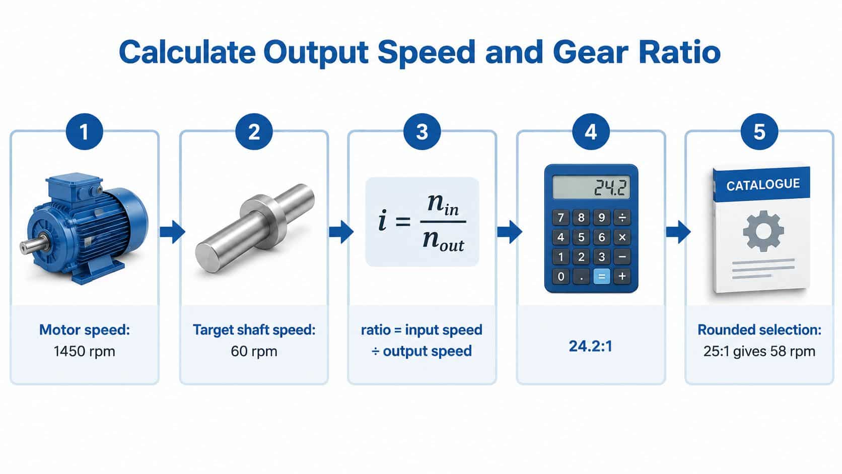
- Read the rated speed from the motor nameplate. A four-pole induction motor on a 50 Hz supply synchronises at 1500 rpm and runs at roughly 1450 rpm on load. Use the loaded figure.
- Write down the output speed the process needs. Take it from the machine specification, not from whatever the old gearbox happened to deliver.
- Divide input speed by output speed. 1450 ÷ 60 = 24.17. Round only at the end.
- Pick the nearest catalogue ratio and recalculate. Divide 1450 by the ratio you've chosen, so you're quoting the speed the machine will run at.
From a 1450 rpm input, these six ratios cover most of what comes through a workshop:
| Ratio | Typical application |
|---|---|
| 5:1 (290 rpm) | Fans and light pump drives |
| 10:1 (145 rpm) | Conveyors and light mixers |
| 20:1 (72.5 rpm) | Mixers and agitators |
| 40:1 (36.3 rpm) | Winches and hoists |
| 60:1 (24.2 rpm) | Slow indexing tables |
| 100:1 (14.5 rpm) | Slow rotating platforms |
A quick check catches most slips: multiply the output speed back by the ratio and you should land on the input speed. 14.5 × 100 = 1450, so that row is sound.
The trade is the same one riders make when they change sprockets, where lower gearing buys torque and costs speed. If the concept is easier to picture on two wheels, this gearing guide for track-day riders explains it without industrial notation getting in the way.
What none of this tells you is whether the unit will survive. Two reduction gearbox ratios reading 25:1 on the label can differ by a factor of two in thermal capacity, and only one of them is still running in five years on a continuous mixer. The ratio is the start of the specification, never the end of it.
Size Output Torque and Power From Motor Data
A 7.5 kW motor at 1450 rpm driving a 20:1 gearbox at 95 per cent efficiency is worth working through because every figure is checkable on a calculator.
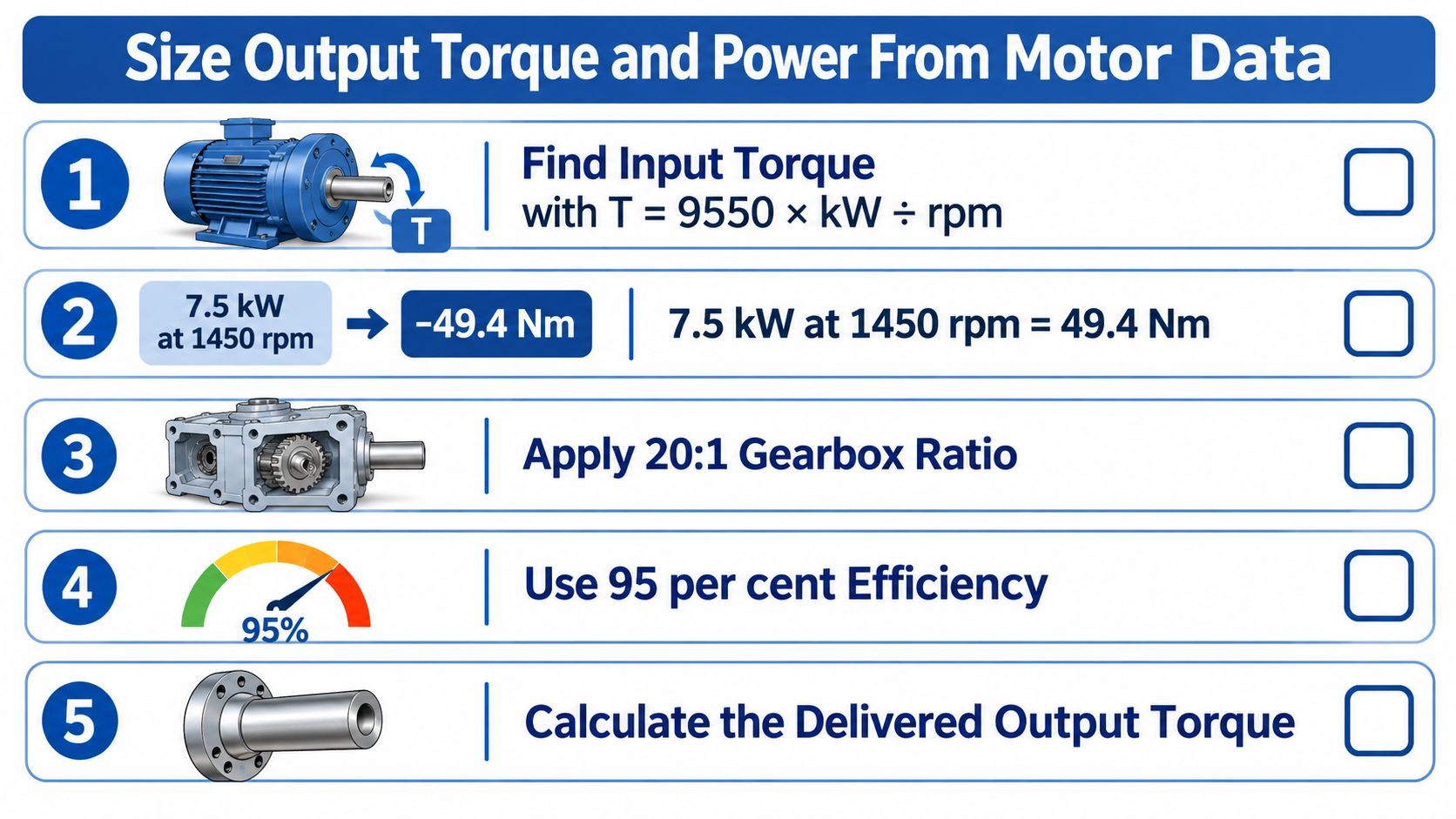
- Find the input torque. T = 9550 × kW ÷ rpm, so 9550 × 7.5 ÷ 1450 = 49.4 Nm.
- Multiply by the ratio for theoretical output torque. 49.4 × 20 = 988 Nm. That's the number a catalogue would quote if gearboxes were lossless.
- Apply efficiency. At 95 per cent, 988 × 0.95 = 939 Nm delivered. The missing 49 Nm becomes heat in the oil and the casing.
- Work out the output power. 7.5 kW × 0.95 = 7.1 kW. Speed fell twentyfold, torque rose roughly nineteenfold, and power never rises.
- Compare against the machine's requirement plus margin. If the load needs 800 Nm continuous, 939 Nm looks comfortable until shock enters the picture. Check starting and stall torque on the motor datasheet, because a direct-on-line start can demand several times running torque.
Run the sums in this order every time: input torque, then ratio, then efficiency. Doing efficiency first gives the same answer but hides which side of the drive is losing power when you're fault-finding at 2am.
Keep every figure metric: torque in newton metres, power in kilowatts, speed in revolutions per minute, mounting dimensions in millimetres. UK trade law requires metric units as the primary system for most goods sold by quantity, as set out in the government guidance on units of measurement. An imperial equivalent alongside is a courtesy for comparison; the metric figure stays the specification. If you're working back from the motor instead, how to size a motor covers the input side of the chain.
Seeing the relationship animated helps when you have to explain it to whoever signs the purchase order.
Choose the Gearbox Type for Your Ratio and Duty
Every gear type has a practical ratio ceiling per stage, so a high reduction usually means more stages, more losses and more cost. The comparison below is the one I'd sketch on the back of a quote.
| Gearbox type | Typical ratio per stage | Typical efficiency | Best fit |
|---|---|---|---|
| Planetary | 3:1 to 10:1 | 95 to 98 per cent | Compact, high-torque mobile drives |
| Helical parallel shaft | 3:1 to 6:1 | 94 to 98 per cent | Quiet conveyor and industrial drives |
| Helical bevel | 2:1 to 6:1 | 93 to 97 per cent | Right-angle drives in tight spaces |
| Worm | 5:1 to 60:1 | 50 to 90 per cent | Intermittent low-speed, self-locking duty |
| Spur | 2:1 to 6:1 | 97 to 98 per cent | Simple, low-cost low-ratio drives |
Read the efficiency column hardest when the ratio climbs. A worm unit at 30:1 can run anywhere between 50 and 90 per cent depending on lead angle and lubrication, while a planetary stage typically clears 95 per cent. On the 7.5 kW drive above, a worm at 50 per cent delivers around 494 Nm at the output where a planetary at 95 per cent delivers 939 Nm. That's the difference between a casing that runs warm and one that needs cooling or a shorter duty, and it's why ratio and gear type have to be chosen together.
Three questions that narrow the choice
- How much ratio will the space give you per stage? An inline helical unit needs length along the shaft line, a planetary set needs diameter. If neither fits, the machine layout decides for you.
- Which shaft orientation does the machine dictate? A right-angle bevel gets the motor out of the way of an operator or a guard where an inline unit would foul it.
- Is the duty continuous or intermittent? Worm units suit short, self-locking movements where the drive must hold position; helical and planetary suit continuous running where heat accumulates hour after hour.
Two of those answers usually settle it. Then it's back to the torque and heat checks before anything is ordered.
Checks Beyond the Ratio for Heat, Duty and Compliance
A gearbox can deliver the target output speed and still overheat in service. That happens when its thermal capacity is too low for the load, ambient temperature or operating cycle, even though its mechanical rating appears adequate.

Power lost inside the gearbox becomes heat in the oil. A unit sized for intermittent running may exceed its thermal rating if the machine starts frequently under load or changes to continuous duty. A ratio change does not remove the need to check operating conditions.
The four checks that decide it
- Continuous thermal rating in kW. Mechanical and thermal ratings are separate limits. Check that the gearbox can dissipate heat at the expected ambient temperature and duty.
- Peak and shock torque. Use the highest load in the cycle, not just the average. A mixer starting with settled solids can require considerably more torque than it uses while running.
- Radial and axial shaft loads. Belts, chains and overhung pinions load output bearings independently of transmitted torque. Provide the pulley diameter and belt pull when checking the bearing rating.
- Lubrication and mounting. Confirm oil grade, level, breather position and mounting attitude. A change of orientation can affect lubrication, so re-check the oil level and breather before starting the unit.
Apply the service factor to rated torque to account for load variation:
- 1.0 for uniform loads, such as a steady conveyor or fan.
- 1.25 to 1.5 for moderate shock, such as a mixer starting under load.
- 1.75 to 2.0 for heavy shock, such as a crusher drive.
The required margin depends on the consequences of failure. Critical plant generally needs more torque margin than mobile or non-critical industrial equipment. Set the margin against the actual load profile and the cost of an unplanned stop.
A ratio change can also alter machine speed, reach and stopping behaviour. Check pinch points and guarding against the applicable machinery safety requirements, including PUWER and the Supply of Machinery (Safety) Regulations. If the shaft position or coupling length changes, check the guard again rather than assuming the existing arrangement still protects the moving parts.
Record the duty cycle before choosing a gearbox. Note starts per hour, load at each stage, ambient temperature and run time per shift. Use duty-cycle guidance for gearbox sizing to describe how the machine operates and identify the rating it needs.
Deciding Whether a Near Ratio Is Enough
The question that comes up most from maintenance teams is whether a small mismatch is acceptable or whether the unit has to be changed. It depends on whether the machine can absorb the altered speed, torque and motor loading. The cheapest ratio isn't always the lowest-cost drive across its service life.
| Situation | Action | Reason |
|---|---|---|
| Output speed within a few per cent and torque margin intact | Retain | Small deviation is harmless if load and temperature stay normal |
| Speed off target and machine tolerates it | Re-ratio the control settings | Avoids a gearbox change while meeting the process need |
| Oil running hot or unit noisy but ratio correct | Repair or inspect | Worn components are the cause, not the ratio |
| Continuous torque or thermal rating exceeded | Replace with a suitable ratio and rating | Higher duty needs a unit rated for it |
| Guarding or warranty affected by change | Replace and re-check guarding | Compliance and warranty must be preserved |
Measure the old unit before you condemn it
Comparing catalogue ratios tells you almost nothing. Compare the old and proposed unit on input power, output speed, load profile, temperature rise, oil condition and operating hours. Those six figures describe the machine as it runs, and they're what show whether a mismatch is already costing money in wasted energy or throttling losses.
UK engineering commentary on driving down energy waste in motor-driven systems makes the case for right-sizing gearing and replacing worn or inefficient units, and notes that inspection and repair facilities cover gearboxes of different types and sizes. When a worn bearing is the fault, repair is the cheaper route and the ratio was never the problem.
The question isn't whether the ratio is exact. It's whether the machine can tell the difference.
A 1450 rpm motor on a 25:1 unit returns 58 rpm; a 24:1 returns 60.4 rpm, about 4.1 per cent high. A conveyor that tolerates a couple of extra revolutions per minute keeps its gearbox and its budget. A press that needs 58 rpm to hold timing against another axis is re-ratioed or replaced, because that error accumulates every cycle. Check temperature rise and torque margin before deciding either way, since a 4 per cent speed increase can push a marginal unit past its thermal limit.
Record the decision. Note the figures you compared, the temperatures and the date, so the next service interval checks the same numbers instead of starting again from a catalogue page.
Confirm Your Specification Before You Order
Five confirmations separate a specification from a guess.
- Input speed and rated kW from the motor nameplate, using loaded figures.
- Required output speed and the resulting ratio, plus what the nearest catalogue unit delivers.
- Output torque with efficiency applied, and a margin for starting or shock loads.
- Duty cycle and thermal rating for the continuous running the machine sees.
- Shaft orientation, mounting dimensions in millimetres and radial load from belts, chains or overhung pinions.
MA Hydraulics stocks reduction gearboxes from the Borelli range, alongside KRS aluminium and cast iron agricultural PTO gearboxes and lever operated and electro-mechanical clutches. That means we can match a ratio to a duty, cross-reference a part number or check a replacement against the unit you're taking off.
If the motor or coupling is changing at the same time, coupling a motor to a shaft covers alignment and fit before the gearbox goes on.
Call 01724 279508 today with the nameplate figures, the output speed and the duty, or send the numbers through the contact form at the MA Hydraulics contact page. The team is based in Scunthorpe and will review your figures before you commit to a unit.
MA Hydraulics Ltd supplies reduction gearboxes, PTO gearboxes, clutches, couplings and hydraulic components from Scunthorpe, and we'll check a ratio against your duty before anything is ordered. Send us the motor nameplate, the output speed you need and the duty cycle, and we'll come back with the ratio and rating that fit the machine rather than the catalogue page. Call 01724 279508 today, or visit MA Hydraulics Ltd to see the full gearbox range.
