
You're usually called in after the easy decisions have already been made. The motor is on the floor, the pump or gearbox is waiting, someone has measured the shaft once, and the question lands as if it's simple: can we just get the coupling on and run it?
That's where coupling motor to shaft goes wrong.
On a hydraulic drive, the coupling isn't an isolated part. It sits in a rotating assembly that includes the motor shaft, the driven shaft, the key, the hub fit, the baseplate, the pipework loads, the guard and the alignment method. If any one of those is treated casually, the coupling often takes the blame for a failure that started somewhere else.
Why Coupling Motor to Shaft Is More Than a Part Swap
A motor arrives, the pump is already bolted down, and somebody has the coupling half in a box ready to fit. That job looks simple for about five minutes. Then you find a polished shaft with a bruised keyway, a baseplate that is not sitting flat, and pipework that will pull the pump sideways as soon as the last flange is tightened.
That is why coupling motor to shaft has to be treated as a rotating assembly job, not a parts counter exercise. The coupling only sits in the middle. The outcome depends on shaft geometry, key fit, hub fit, alignment, support stiffness, vibration and guard access after the machine goes back into service.
On hydraulic drives, that matters because the coupling often gets blamed for faults that started elsewhere. A flexible element torn after a few weeks can point to angular misalignment. Fretting on the key can point to poor fit or movement in the hub. Repeated seal leaks or bearing noise can point to pipe strain or soft foot loading the machine frame. Swapping the coupling without addressing those conditions usually buys a short quiet period and then the same failure again.
In UK workshop practice, the starting point is normally standard shaft and key dimensions, not guesswork at the bench. DIN EN 50347 is commonly used for IEC motor interface and shaft details, DIN 6885 for parallel keys and keyways, and DIN 740 for flexible coupling arrangements and terminology. Those standards do not install the job for you, but they stop basic fit errors before you even start checking running conditions.
Before fitting, check these points on the actual assembly:
- Torque behaviour: steady pump duty is one thing. Repeated starts, pressure spikes, reversal or braking duty are harder on the coupling and key.
- Shaft and hub condition: worn keyways, raised burrs, undersize keys and fretted bores change how the torque is carried.
- Machine stiffness: a fabricated skid, tank top or light frame can move enough under load to alter alignment after assembly.
- External loads: hose and pipe strain, belt pull from adjacent equipment, or poor support under the driven unit can shift the shaft centreline.
- Access after guarding: if no one can get a straight edge, dial indicator or laser head onto it later, rechecks tend not to happen.
- Work equipment compliance: if the replacement changes guard clearance, pinch points or maintenance access, the job needs checking against the site's PUWER arrangements, not just the stores issue note.
A quick rule from the shop floor helps here. If the only information on the job sheet is motor power, shaft diameter and “flexible coupling,” the assembly has not been specified well enough.
There is also a long UK manufacturing history behind this. Flexible couplings have been established industrial products for decades, and suppliers such as Renold document that development in their company presentation. The practical lesson has not changed. A coupling lasts when the motor, shafting, fit and support structure are treated as one rotating system.
Choosing the Right Coupling Type for the Job
A coupling choice usually gets tested the first time the hydraulic motor starts under load, not when the stores bin says the bore fits. On a pump set, the coupling has to suit the whole rotating assembly. That includes how stiff the base is, how much starting shock the driven side sees, how accurately the shafts can be held in line, and what access remains once the guard is back on.
No coupling family covers every duty well. A flexible insert can help with torsional shock and small movement, but it does not turn a poor installation into a good one. For practical hydraulic work, motor shaft couplings for hydraulic drives are best selected by duty, shaft arrangement and maintenance conditions, not by torque and bore alone.
What each type does well
Rigid couplings belong on shafts that are already aligned closely and mounted on a structure that does not wander under load. They suit short, direct arrangements where positional accuracy matters more than forgiveness. If the skid flexes or the motor feet are packing on uneven steel, a rigid coupling usually exposes that fault quickly.
Jaw couplings are common on hydraulic packs because they are compact, easy to strip, and give a degree of damping through the spider. They are often a sensible answer for general pump duty where the baseplate is decent and the motor starts are not especially harsh. The trade-off is insert life. Heat, oil contamination and repeated shock can harden or break the element long before the hubs show much wear.
Gear couplings earn their place on higher torque drives, especially where a metallic coupling is preferred and there is enough room for the assembly and its maintenance points. They carry load well, but they are not fit-and-forget items. If lubrication gets missed or alignment is left outside the maker's limits, backlash, wear and vibration tend to follow.
Grid or spring couplings suit machinery that sees shock loading, cyclic disturbance or abrupt load changes. They can soften the effect of those events on the motor shaft and key. The compromise is size, and sometimes guarding space, which matters on compact hydraulic power units.
Disc and diaphragm couplings suit higher speed work, low backlash arrangements and duties where torsional stiffness matters. They are precise components. That precision comes with less tolerance for sloppy mounting, soft feet or casual alignment practice.
Oldham couplings are useful where parallel offset is known and controlled, and where the duty stays within a light to medium range. They are less forgiving of abuse than their simple layout suggests, so they are rarely my first choice for a hydraulic installation that may see contamination, shock or irregular maintenance.
Coupling Types Compared for Motor-to-Shaft Use
| Coupling Type | Misalignment Handled | Typical Torque Range | Best Suited For |
|---|---|---|---|
| Rigid | Very little tolerance for angular, parallel or axial error | Broad, depending on construction | Precisely aligned shafts on stiff bases |
| Jaw | Small amounts of angular, parallel and axial movement | Light to medium industrial duties | General hydraulic pump drives and small power packs |
| Gear | Handles misalignment within its design envelope while carrying high torque | Medium to heavy duty | High torque industrial drives |
| Grid or spring | Moderate misalignment with shock absorption | Medium to heavy duty | Shock-loaded plant and driven equipment |
| Disc or diaphragm | Small misalignment with high torsional stiffness | Light to heavy, depending on design | High-speed or low-backlash installations |
| Oldham | Predictable parallel offset | Light to medium duty | Compact drives where offset is the main issue |
What usually works in practice
For ordinary hydraulic pump service on a sound baseplate, a jaw coupling is often the cleanest option because it balances simplicity, serviceability and tolerance for normal running conditions. Once the duty involves heavier inertia, reversing load, frequent starts or visible torsional disturbance, the coupling choice needs to move with it.
A useful shop-floor check is to ask what problem the coupling is being asked to solve. If the answer is shock, choose for shock. If the answer is high torque, choose for torque. If the answer is "alignment will be awkward", fix the mounting and alignment method first, because flexibility in the coupling does not remove the load from the motor bearings, key or shaft.
Sizing the Coupling, Bore and Keyway
Good sizing starts with the driven machine, not the coupling shelf.
A pump, fan, gearbox or conveyor doesn't load the shaft in the same way, so torque demand has to be established from the duty and any service factor used by the coupling manufacturer. After that, check the coupling's nominal and peak torque ratings against the application. Rough horsepower matching is how undersized hubs and overloaded inserts end up back on the bench.
Bore and shaft standard first
On motor work in the UK, the bore should be matched to the motor shaft standard, not opened up “close enough” and hoped for the best. The practical route is to use DIN EN 50347 for IEC motor shaft diameters and shaft lengths, then choose the hub bore and keyway to suit that shaft standard.
For keyed hubs, DIN 6885 is the normal reference point for the key and keyway form. The point isn't paperwork. It's repeatable fit. If the shaft, key and hub are each made to recognised dimensions, you remove one of the biggest causes of assembly trouble.
Why BS 46 still matters on keyed fits
British Standard BS 46 gives a detail that a lot of people miss during inspection. The shaft keyway depth is measured from the circumference diametrically opposite, or from the hub bore to the root of the keyway along the centre line diametrically opposite, not from the side corner, and the standard also states a 1 in 100 basic taper for taper keys and keyways in hubs, with shaft and hub keyway widths set on minus and plus tolerance respectively, as shown in the SKF coupling reference that cites BS 46.
That sounds minor until you're checking a replacement hub that “looks right” but doesn't seat the key properly.
If the key rocks, sits proud, or bottoms in the wrong place, the coupling won't transmit load the way you think it will.
Practical sizing checks on the bench
Use this sequence before approving the parts:
- Confirm shaft standard: Check motor shaft diameter and usable length against the applicable motor standard.
- Match bore and keyway: The hub bore and keyway should match the shaft and key specification, not a near equivalent.
- Check hub length: The hub needs to cover the working key length properly.
- Inspect root and edges: Burrs, corner damage and poor machining at the keyway root are warning signs.
- Think about future removal: A fit that goes on roughly usually comes off worse.
For hydraulic motors and pump drives, this part of the job often decides whether the coupling stays concentric and serviceable or starts fretting at the bore after a short period in service.
Preparing Shafts, Keys and Hubs for Installation
A coupling job usually starts going wrong before the motor is even lifted into position. The bore looks clean enough, the key came out of the old hub, and someone reaches for a soft hammer to “persuade” the new half on. That is how you build runout, fretting and repeat seal failures into a hydraulic drive before first start.
Treat the shaft, key and hub as one rotating assembly. If those three parts do not seat properly together, no flexible element will rescue the installation for long.
Bench checks before the parts go near the machine
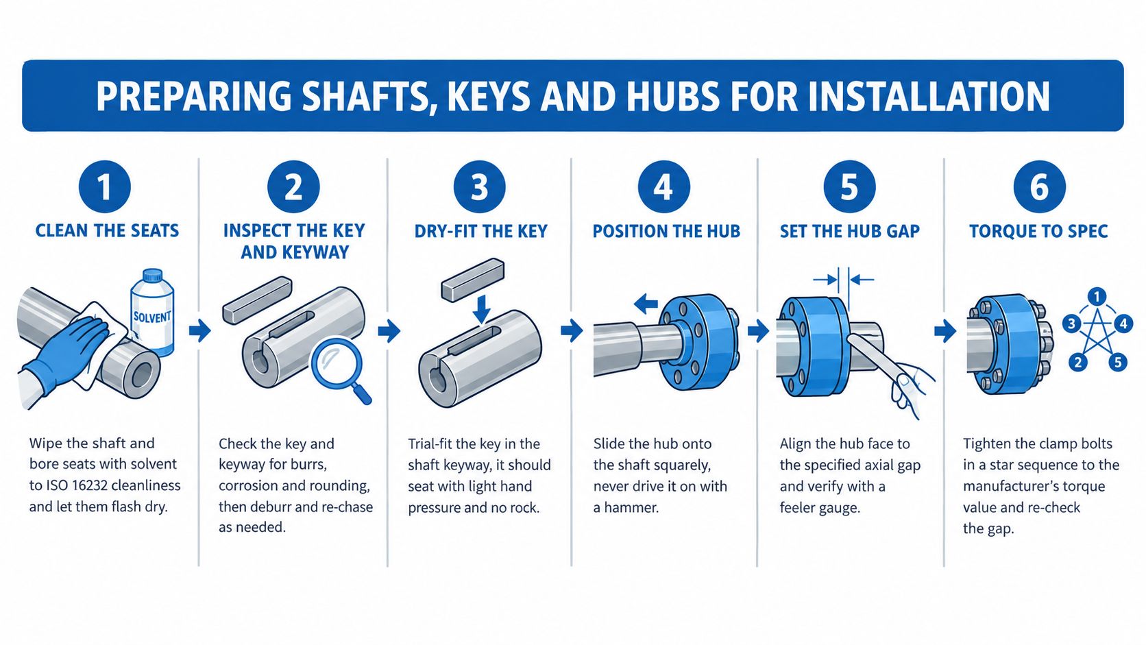
Start with cleanliness, but do not stop there. Wipe the shaft seat, the bore, the key and both keyways until there is no oil varnish, grit, old retaining compound or raised corrosion left on the contact faces. A light stone on bruised edges is often enough. If you have to remove visible high spots, check the fit again instead of forcing the hub over them.
Then inspect the condition of the parts in the places that control concentricity and torque transfer.
- Shaft seat: Look for burrs, pitting, fretting marks, old grub screw damage and a battered lead-in.
- Key and keyway: Trial-fit the key by hand. It should sit square, with no rocking and no need to drive it home.
- Hub bore: Check for scoring, pickup, bell-mouthing and any witness marks from a previous loose fit.
- Hub face and shoulder: Confirm the hub will pull up square if the design locates against a shaft shoulder or spacer.
Fit the parts in a controlled sequence
Dry-check the hub on the shaft first if the fit allows it. That tells you quickly whether the problem is dirt, burrs, key height or a bore issue. On keyed assemblies, fit the key, offer the hub up square, and make sure the hub is sliding over the key rather than shaving its top edge.
If the coupling uses an elastomer element, replacing a worn spider for coupling applications only makes sense after the metal fits have been checked. A fresh insert can hide a poor hub fit for a short time, especially on hydraulic motor drives that see reversing load or pressure ripple.
Heat-fit methods, taper bushes and clamp hubs all have their place. The trade-off is straightforward. Interference and shrink fits give strong concentric location, but they demand better preparation and make later removal harder. Taper bushes are quicker to service, but they must be pulled in evenly or they will skew the hub and introduce runout. Clamp styles avoid marking the shaft, provided the shaft tolerance and bolt tightening are right.
A hammer is still the wrong tool for any of them.
A hub that starts onto the shaft out of square usually stays out of square, even if the bolts pull it the rest of the way.
Final installation checks that prevent repeat failures
Set any specified hub gap or face distance with a gauge, not by eye. Tighten grub screws, clamp bolts or bush screws in stages and in an even pattern. After each stage, recheck hub position, key security and whether the hub still turns true on the shaft.
This part matters on UK hydraulic installations because the coupling is only one part of the duty. Shaft damage, poor key contact and hub runout feed straight into vibration, bearing load and guard compliance problems once the machine is back under pressure. A clean, square fit on the bench saves far more time than chasing vibration after commissioning.
Aligning the Motor and Driven Shaft
Alignment is where the job becomes real. The coupling can only work within the shaft positions it's given. If the motor and driven shaft centre lines are wrong, the flexible element, bearings and seals pay for it.
Three directions that all matter
Alignment on flexible couplings has to be checked in axial, parallel and angular directions. For one common flexible coupling range used in UK industry, published installation limits for size 1010G are 0.05 mm parallel offset and 0.15 mm angular misalignment, with operating limits of 0.66 mm and 1.80 mm respectively, according to UK Flowtechnik gear coupling guidance.
That gap between installation and operating limits matters. Installation is where you aim. Operating allowance is not a licence to leave it crooked.
Acoem's UK guidance gives a widely used precision benchmark at 1800 rpm of 0.7 mils per inch angular and 4.0 mils offset, and stresses that the workflow should move from clean fit-up to dial-indicator verification and then iterative shim or machine movement until both angular and parallel values are inside tolerance, as explained in Acoem's shaft alignment article.
Typical alignment acceptance bands for motor-to-shaft couplings
| Coupling family | Parallel offset (mm) | Angular misalignment (°) | Notes for hydraulic drives |
|---|---|---|---|
| Flexible coupling, tight installation example | 0.05 | Qualitatively tight | Suitable as a careful installation target where maker guidance is strict |
| Gear coupling size 1010G installation limit | 0.05 | 0.15 | Use as published installation limit for that coupling size |
| Precision benchmark at 1800 rpm | Offset benchmark stated as 4.0 mils | Angular benchmark stated as 0.7 mils per inch | Convert carefully in workshop method if working in metric |
A short visual refresher can help if the team needs to agree what's being measured before adjustment:
The method that works on the floor
Use a dial indicator, reverse dial setup or laser system. UK guidance for gear couplings recognises micrometer, space bar, laser alignment or reverse dial indicator methods, which gives maintenance teams a practical choice rather than a vague instruction to align carefully.
The sequence should be disciplined:
- Check soft foot first: If one motor foot is high, the readings lie to you.
- Set angular alignment: Rotate through a full revolution and find the minimum-reading point if using the disc-coupling style dial method.
- Correct parallel offset: Move the machine sideways or shim as needed.
- Recheck after every correction: One change affects the other.
- Verify before guards go back on: Don't sign off from memory or “near enough”.
For vibration-related issues after commissioning, vibration analysis on rotating hydraulic equipment often tells you whether the alignment error is still present or whether another load path is now disturbing the shaft line.
Why Flexibility Is Not a Substitute for Alignment
A motor comes back from stores with a flexible coupling fitted, the shaft heights look close, and someone says the insert will take up the error. That is how a simple hydraulic motor change turns into bearing noise, seal wear and a coupling hub that starts fretting on the shaft a few weeks later.
Flexible couplings are built to absorb small residual movement within a properly set shaft line. They are not there to carry a poor installation. On a hydraulic power pack or driven pump set, that distinction matters because the coupling is only one part of the rotating assembly. The motor bearings, shaft seal, key, hub bore and driven machine all feel the same error.
Published misalignment figures are often read too casually. As noted earlier, the stated limits for lateral, axial and angular error are not a free pass to use the full value in every direction at once. Once offset, angle and axial movement appear together, the allowable condition tightens quickly. That is the workshop problem, because machines rarely move in one plane only after pipework is connected and the base settles hot.
I see the same pattern on site. The coupling element survives long enough to give false confidence, while the rest of the assembly pays for it.
What usually suffers first is not always the visible flexible element:
- Motor bearings pick up extra radial and axial load, which shortens life and changes running noise.
- Shaft seals wear faster when the shaft is being pulled off its true centre line.
- Keys and keyways start marking and rocking if the hub is working back and forth under cyclic load.
- Hub bores fret against the shaft when fit is only just acceptable and alignment is poor.
- Holding-down bolts and coupling fasteners lose preload as the assembly keeps moving under load.
- Vibration levels rise across the machine, which then gets blamed on the motor alone.
On hydraulic installations, heat and pipe strain make this worse. A unit can align acceptably when cold, then move once the oil is up to temperature and the connected pipework starts pushing or pulling on the motor bracket. That is why coupling motor to shaft needs treating as a running system, not a bench assembly exercise.
A flexible element should accommodate controlled residual misalignment, torsional behaviour and normal thermal movement. It should not be asked to mask bad geometry. If the team relies on coupling flexibility instead of getting the shaft line right, the coupling may keep turning, but the assembly is already wearing in the wrong places.
First Run Checks, Testing and Ongoing Maintenance
The first proper run is where a coupling job proves itself. On hydraulic sets, plenty of assemblies look acceptable on the stand, then start showing their real behaviour once the oil warms, the bracket settles, and pipework begins loading the motor feet. Treat that first start as a check on the whole rotating assembly, not just the coupling element.
Before you couple anything, bump the motor uncoupled and confirm rotation is correct for the driven unit. Then assemble the coupling, fit the guard well enough for safe running, and bring the machine up in stages. A short low-load run, a stop, and an inspection will usually tell you more than going straight to full duty and hoping for the best.
First run checks that catch problems early
Use the same routine each time so faults are easier to spot and records mean something later.
| Stage | Action | Acceptance Criterion |
|---|---|---|
| Before coupled start | Confirm motor rotation direction and free movement | Rotation matches driven equipment requirement and nothing binds |
| After assembly | Verify fasteners, hub position and guard condition | All fasteners secure, hub gap set, guard arrangement intact |
| Initial running period | Check bearing temperature trend and listen for cyclic noise | Temperature should stabilise normally for the machine and no repeating knock or scrape should appear |
| Early stop inspection | Recheck bolts, visible movement and coupling condition | No loosening, no fresh fretting, no abnormal axial movement |
| Settling check | Recheck alignment and retorque after early service | Alignment remains within target and fasteners return to specified torque |
| Routine maintenance | Visual inspection and condition monitoring | No cracking, looseness, guard damage or rising vibration trend |
A short settling recheck matters. Disc coupling instructions used widely in UK industry call for the alignment to be checked again after early operation and for bolts to be retightened to the specified torque. That matches what happens on site. Freshly disturbed bases, new shims, repainted feet, and bracket movement can all alter readings after the first few hours.
Do not rely on visual fit-up. A coupling can look central and still run with enough offset or angular error to load bearings, mark keyways, and shake the machine once speed comes up.
If the machine is important, write the job down properly. Record final alignment readings, shim changes, fastener torques, hub positions, and anything unusual such as pipe strain or a soft foot correction. That note is often what saves time on the next shutdown.
Maintenance signs that mean the coupling needs attention
Couplings usually give warning before they fail. The trick is reading the warning in context.
- Fretting at the bore or keyway: The hub is moving on the shaft, or the fit was marginal from the start.
- Polished dust around the hub or key: Small movement is taking place under load.
- Cracking, hardening or wear in elastomer parts: The element is seeing heat, misalignment, shock load, or a mix of all three.
- Loose fasteners: Settlement, poor tightening sequence, or ongoing movement in the assembly.
- Abnormal axial movement: Check thrust control and shaft location, not only the coupling.
- Rising vibration: Measure the machine as an assembly, because the source may be alignment drift, pipe strain, bearing condition, or an issue in the driven unit.
For hydraulic installations, replacement decisions need a wider view than bore size and outside diameter. Shaft support, key fit, motor mounting position, side load from chain or gearbox drives, and the vibration behaviour of the complete train all matter. As noted earlier, that full-assembly approach is what separates a sound repair from a coupling that survives briefly while the motor and driven shaft wear around it.
The compliance side of the job
A coupling swap can change the safety position of the machine. Guard clearances, access for maintenance, exposed rotating parts, and vibration behaviour all sit under work equipment duties, which is why the HSE work equipment and machinery guidance page is relevant to the job, not just to paperwork.
On the shop floor, the practical question is simple. After the new coupling is fitted, aligned, guarded, and run, is the machine still safe to use and maintain?
Keep an evidence trail. Alignment record, torque record, guard arrangement, and any note about vibration or pipe strain all help show that the assembly was checked as installed, not assumed to be right because the part numbers matched.
MA Hydraulics Ltd supports coupling motor to shaft work with practical component matching, bore and keyway considerations, and help on hydraulic drive assemblies where alignment, shaft loading and replacement risk need checking properly. If you need help specifying or troubleshooting a coupling on a motor and driven shaft, visit MA Hydraulics Ltd, phone 01724 279508 today, or send a message through their contact page.
