
The usual advice is to replace a ball valve with another of the same size. That's not enough. A 1 1/4 ball valve can carry the right trade label yet have the wrong thread, a restrictive bore or an unsuitable pressure rating.
Treat the size as a starting point for identification, not permission to install. For maintenance teams, the useful questions are whether the replacement fits without strain, passes the required flow and remains safe at the actual fluid temperature and pressure.
1 1/4 Ball Valve Dimensions and Ratings at a Glance
The 1 1/4 inch label is a trade designation, not a complete measurement. It does not specify the valve's bore, overall dimensions or safe operating pressure. The table below gives one product example, not a standard for every valve sold under that size.
| Attribute | Value | Note |
|---|---|---|
| Nominal trade size | 1 1/4 in | Common trade designation |
| Metric designation | DN32 | Cross-reference used by UK and European suppliers |
| Converted size | 31.75 mm | Exact conversion from inches, not a thread diameter |
| Nominal bore | 20 mm | Reduced-port value for the cited product; confirm per valve |
| Body dimension A | 78 mm | Manufacturer’s drawing reference |
| Body dimension B | 56 mm | Manufacturer’s drawing reference |
| Body dimension C | 103 mm | Manufacturer’s drawing reference |
| Weight | 0.52 kg | For the cited product |
| Pressure rating | Read the pressure-temperature table | The applicable rating depends on the stated operating conditions |
| Next size up | Check the selected product’s datasheet | Do not assume the bore from the nominal size |
The valve dimensions, weight, designations and pressure information above refer to one UK-market product, the Socla X1666 technical datasheet. The exact inch conversion follows the Units of Measurement Regulations 1995. Neither source establishes the dimensions or performance of every 1 1/4 inch valve.
Read the drawing before comparing bodies
Start with the manufacturer's dimensional drawing. A, B and C are drawing references, not universal labels for length, height or handle clearance. Check what each dimension measures on the specific product.
The bore is the internal passage through the valve. It can be smaller than the nominal connection size, as the 20 mm reduced-port figure in the table illustrates. A same-size replacement can therefore fit the pipework yet restrict flow compared with the valve it replaces.
Practical rule: A valve that screws into the pipework has passed only the initial fit check.
Confirm the end-to-end length, thread form and installation envelope against the existing assembly. Then check the manufacturer's pressure-temperature table for the actual fluid and operating conditions. A suitable pressure rating cannot compensate for incorrect dimensions or connections.
Check handle travel and tool access before ordering. A compact body may fit between adjacent equipment, but still leave too little clearance to operate or service the valve.
Use these figures only as a product-specific comparison. Confirm the required connection and dimensions against the pipework, machine schematic and selected manufacturer's drawing, then verify the operating rating for the service conditions.
Connection Types and Thread Standards Compared
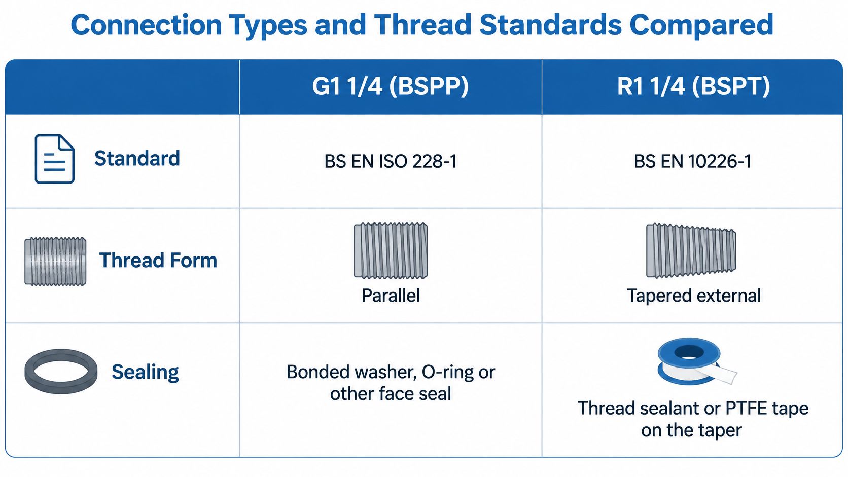
The “1 1/4 inch” label is a trade size, not a measurement that identifies the connection. Confirm the thread form, sealing method and mating design before substituting a valve. A connection that starts to screw together can still leak or damage the threads.
| Designation | Standard | Sealing method | Check before ordering |
|---|---|---|---|
| G1 1/4, BSPP parallel | BS EN ISO 228-1 | Bonded washer, O-ring or face seal | Confirm the mating part uses the specified sealing face and seal |
| R1 1/4, BSPT tapered external | BS EN 10226-1 | Thread engagement with suitable sealant | Use a compatible female connection specified for the tapered male thread |
| Rp 1 1/4 internal, parallel | BS EN 10226-1 | Seals through engagement with a matching R tapered external thread, using suitable sealant | Check the mating thread and sealing requirements on the datasheet |
| Compression ends | BS EN 1254 | Compression fitting | Match the pipe outside diameter to the fitting |
The BSP thread-size guide from MLC gives a nominal 1 1/4 BSP thread as 11 threads per inch, with a 2.309 mm pitch and an approximately 41.910 mm major diameter. It distinguishes G parallel threads from R tapered external threads. These dimensions explain why measuring across the thread will not match a direct inch conversion.
Use the comparison graphic to check the difference between thread form and sealing arrangement.
Similar appearance doesn't mean the same seal
In a BSPP assembly, the specified washer, O-ring or face seal generally forms the pressure boundary. Thread tape cannot make up for a missing sealing face or an unsuitable washer.
A tapered external connection seals through thread engagement with suitable sealant. A parallel female port is compatible only when its design matches the mating connection and sealing method. For example, an Rp internal thread is specified to mate with a matching R tapered male thread, while a G port may rely on a washer or face seal. Check the port specification rather than judging by appearance.
Specify the end arrangement clearly:
- Female/female: Confirm the internal thread and the fittings that enter each end.
- Male/female: Identify which connection faces each side of the installation.
- Male/male: Check both mating ports and how the valve can be assembled without damaging the threads.
The guide to hydraulic fitting types helps distinguish connection families before you compare individual products.
Identify the thread on site
Clean the thread first. Use a thread gauge to check pitch, measure diameter with suitable equipment, and establish whether the thread is parallel or tapered.
Record those results alongside the nominal designation. Don't use trial fit as identification: if a connection starts but tightens abnormally, stop. Forcing it can damage the thread and still leave the joint unable to seal.
Pressure, Temperature and Material Options
Pressure ratings are product-specific. A stainless body, a familiar thread and the right trade size don't establish hydraulic suitability. The BES stainless-steel reducing-socket listing gives a 10 bar maximum working pressure for that particular threaded fitting, not a universal rating for stainless fittings or ball valves.
That distinction matters when a supplier's catalogue places several component types together. A socket's rating cannot qualify a valve, and a valve's rating cannot qualify the complete assembly.
Check the duty before choosing the material
Obtain the valve's continuous working-pressure limit and compare it with the circuit's maximum operating conditions. Include pump or accumulator transients, maximum fluid temperature, temperature derating and the allowable differential pressure during operation.
The hydraulic ball-valve selection overview is a useful starting point, but the exact product datasheet must settle the application. If a rating is conditional on temperature or medium, retain those conditions in the purchasing specification.
Material descriptions should prompt checks rather than shortcut them:
- Brass body for general water and air duties: Verify permitted media, working pressure and temperature limits. Don't infer drinking-water acceptance from the body material.
- Stainless steel 316 for corrosive or washdown environments: Check the actual material grade and compatibility with both the process fluid and cleaning chemicals. The product-specific threaded-fitting example above isn't a rating for this material family.
- PTFE seat for common operating temperatures: Obtain the seat's permitted temperature range and the assembled valve's pressure-temperature limits.
- PEEK or reinforced PTFE seat for higher temperature or pressure: Consider these only where the manufacturer explicitly qualifies the complete valve for the duty. A seat-material name alone isn't an operating limit.
Specify the assembly, not just the body
Include stem seals and any other wetted seals in the compatibility review. A suitable body material doesn't resolve an unsuitable sealing material.
Likewise, don't specify a reduced-port valve solely because it's smaller or cheaper. Where pressure loss and heat generation matter, assess the flow passage against the duty before accepting the packaging benefit.
The pressure-temperature envelope applies to the assembled valve, not to the strongest-looking part of it.
After fitting, leak-test at the applicable system test pressure under the approved procedure. Inspect the joints, stem and body before releasing the equipment for service.
Potable Water Use and Approval Checks
A correct thread is not a drinking-water approval. An industrial valve can match the pipework perfectly while remaining unsuitable for potable-water isolation.
In England and Wales, the Water Supply (Water Fittings) Regulations 1999 require fittings to prevent contamination and withstand an internal pressure of at least 1.5 times the maximum operating pressure. That requirement isn't a substitute for checking the product's permitted duty or the applicable approval documentation.
Establish acceptance before installation
For a spherical ball valve intended to serve as a stop valve, confirm an integral operating handle and conformity with an appropriate recognised specification. Relevant documentation may include WRAS, Kiwa UK Regulation 4 or NSF Reg 4 acceptance, as applicable to the installation.
Use a documented acceptance checklist:
- Fluid type: Confirm potable water rather than process water, irrigation water or hydraulic fluid.
- Installation jurisdiction: Establish whether the site is in England and Wales, Scotland or Northern Ireland.
- Approval status: Request the certificate reference and verify that it covers the exact product.
- Pressure-temperature envelope: Match the documented limits to the installation conditions.
- Intended function: Confirm isolation duty rather than assuming the valve is suitable for throttling.
Requirements and guidance differ across those jurisdictions. A supplier's general description of UK compliance isn't enough without identifying what it covers.
Consider an industrial hydraulic-circuit valve with matching connections but no supporting water-approval documentation. It fails the procurement acceptance check until the supplier establishes suitability; the thread match doesn't cure the missing evidence.
Request the current datasheet, relevant approval certificate and installation instructions before ordering. File them with the product reference and site records so a future replacement isn't selected from appearance alone.
Cross-References and Equivalent Sizes
A matching trade label does not establish that two valves will fit or perform alike. Treat “1 1/4 in” as a nominal catalogue designation: connection form, actual bore or flow coefficient, and pressure-temperature rating decide whether a replacement is suitable.
| Trade label | Metric or DN | Bore or Kv | Thread | Substitution note |
|---|---|---|---|---|
| 1 1/4 in ball valve | DN32 | Bore or Kv is not established by the nominal size; confirm it for the specific product | G1 1/4 or R1 1/4, as specified | Compare the confirmed bore or Kv, thread form and rating |
| 1 1/2 in ball valve | DN40 | Datasheet example shown in the opening table | Confirm per product | Not a direct substitute for DN32 |
| Belimo DN32 ball valve | DN32 | Kvs 32 m³/h | Rp 1 1/4 internal | Motorised duty; PN25 rated |
The Belimo United Kingdom ball-valve range lists a motorised example with DN32 designation, Rp 1 1/4 internal threads, PN25 rating and Kvs 32 m³/h. These details show why a cross-reference needs more than a matching trade size.
Match the attributes that affect performance
Compare metric designation, thread standard and form, bore or flow coefficient, and pressure-temperature rating as a set. A designation alone cannot confirm fit or duty.
A reduced bore can increase pressure loss. A BSP/NPT mismatch can damage threads or leak, and a room-temperature pressure rating may not apply at higher temperatures. The Altecnic ball-valve installation instructions show the importance of correctly matched connections, clean pipework and adequate support.
Catalogue sizes for neighbouring components are not valve equivalents. A 1 1/2-inch tee has its own component and connection requirements, so its size does not establish a suitable valve substitution.
Build a measured replacement record
Give the supplier identification details that can be checked against the replacement:
- Connection evidence: Thread-gauge result, measured diameter, thread form and clear photographs of both ends.
- Installed dimensions: Pipe outside diameter, valve end-to-end length and available handle clearance.
- Operating duty: Fluid, required flow, normal pressure, peak pressure and maximum temperature.
- Existing identification: Manufacturer, part number, markings and relevant schematic position.
If the valve has been removed, label its orientation and retain the mating fittings for comparison where practical. A damaged sample can help identify the original arrangement, but confirm dimensions independently before ordering.
Scunthorpe-based MA Hydraulics can assist with hard-to-find component cross-references using measured values. State which dimensions are confirmed and which are estimates in the enquiry.
How to Install a 1 1/4 Ball Valve Safely
Use the manufacturer's instructions and the site's authorised work procedure. The graphic is a visual reminder, not a substitute for the isolation plan or the specified tightening and testing requirements.
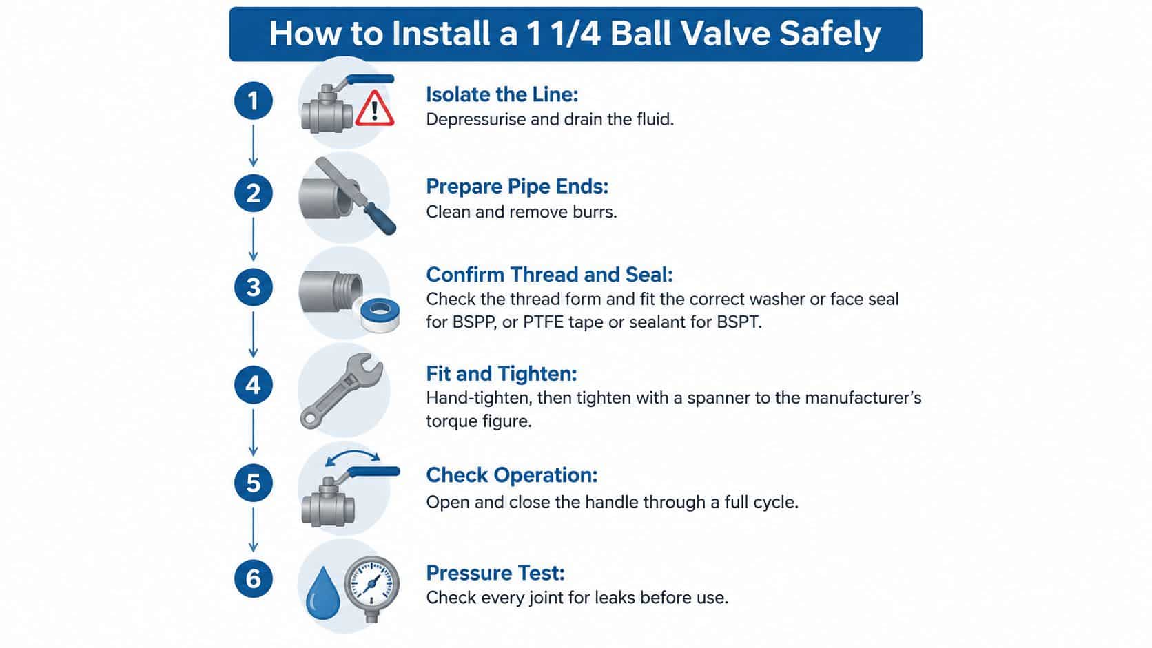
Installation sequence
-
Isolate, depressurise and drain. Secure the isolation and verify that stored pressure has been released, including any connected accumulator. The common mistake is assuming a stopped pump means a depressurised line.
-
Prepare the pipe ends. Clean the connections and remove burrs without leaving debris in the pipework. Don't install over contamination and expect the new valve to tolerate it.
-
Confirm the thread and seal. Use the sealing arrangement established during selection, with the specified washer or face seal for the relevant BSPP joint and suitable sealant for the specified tapered joint. Don't apply sealant as a remedy for incompatible threads.
-
Start by hand, then tighten correctly. Use the designated body wrenching surfaces and the manufacturer's tightening requirements, never the handle as a lever. A forced first turn risks cross-threading; excessive tightening can distort threads or extrude a washer.
-
Support the adjacent pipework. Arrange supports so the body doesn't carry bending loads or pull misaligned pipes together. Don't use tightening force to drag an unsupported line into position.
-
Check orientation and operation. Follow any flow arrow and set the final handle position to the schematic, checking unobstructed movement only under safe conditions. Operate within the manufacturer's limits rather than forcing a stiff handle.
-
Pressurise under the approved test procedure. Introduce pressure in a controlled manner and inspect the threads, seals and body at the applicable system test pressure. Never loosen or adjust a joint while it remains pressurised.
-
Record and release. Document the result and obtain the required authorisation before returning the line to service. Don't treat an undocumented visual check as completion of the site's test procedure.
Confirm the finished installation
For regulated pressure systems, align the work with the site's written scheme and competent-person controls. At the end of the specified hold period, a sound installation has no observed leakage, joint movement or seal extrusion, with the pipework supported and the handle accessible.
The accompanying video is supplementary; retain the written procedure as the working reference.
Before relying on the embedded demonstration, check its rendered frame on desktop and mobile, readable controls, captions and an accompanying transcript. The UK publishing guidance on videos recommends captions and an HTML transcript; Medway Council's video-accessibility guidance also addresses frame width, controls and readable annotations. Check that image and video labels agree with the written connection terminology.
Common Problems and How to Fix Them
A 1 1/4 inch label does not identify the cause of a leak or prove that a replacement will suit the line. Locate where fluid emerges, then diagnose the connection, valve and circuit before changing parts.
| Symptom | Likely cause | Fix |
|---|---|---|
| Leak at the thread | Missing seal or incompatible thread and sealing arrangement | Confirm the mating forms, then replace the washer or re-seal |
| Leak at body or stem | Seal extrusion, assembly damage or over-torque | Isolate and depressurise, inspect and service where permitted; replace a cracked body |
| Stiff or jammed handle | Debris or unsupported pipe load | Clean or flush as appropriate, support pipework, then service or replace |
| Lower flow than expected | Reduced-port bore or debris | Check Cv/Kv, inspect any strainer and select full-port if required |
| Distorted fitting thread | Cross-threading or over-tightening | Replace the damaged fitting and use the correct tool |
| Fails leak test | Damaged seat or body crack | Isolate, replace the valve where required and retest |
Diagnose before replacing
Trace the fluid to its first visible emergence. A leak at the threaded joint points to a different fault from fluid appearing at the stem or body, so dry the area and observe it safely before deciding what to remove.
Then isolate and depressurise the line under the site procedure. Check the seal and thread condition for damage or mismatch, followed by the joint's tightening and the pipe support. A sound valve can still leak if pipe strain loads the connection.
For low flow, compare the fitted bore and published Cv/Kv with the circuit requirement. Don't condemn the pump before checking an obvious restriction. A replacement with a smaller passage can slow a circuit even when its nominal size and connections match the original.
A returning leak calls for a new diagnosis, not another application of the same sealant.
Re-sealing may suit a sound connection. A cracked body or damaged seat calls for a different repair decision. Repeated stem leakage warrants checking for over-torque and side loading, rather than assuming another seal will solve it.
Use a specific check order: locate the leak point, isolate and depressurise, inspect the seal and thread, check joint torque and pipe support, then compare the bore with the required Cv/Kv. For background on a separate domestic water issue, see locate leaks in your home.
Choose the Right Variant and Confirm Before You Order
The 1 1/4 inch label is a trade size, not a complete specification. Fit, flow and safe pressure depend on the thread form, bore, rating and any required approval. Two valves with the same nominal size can fail as substitutes.
The brass valve pictured below shows a lever-operated arrangement. Its appearance does not confirm the pressure rating, internal bore or approval status.
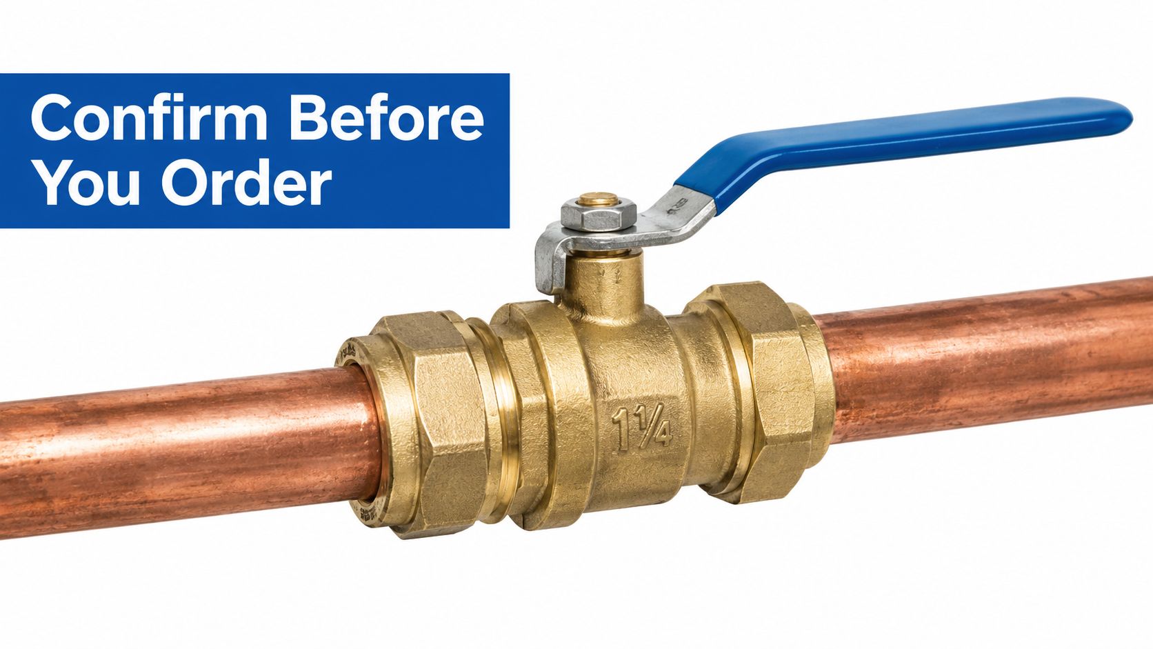
Compare the flow path, not just the label
A proposed replacement may have the same trade size and connections as the installed valve but a smaller, reduced-port passage. It may fit the pipework while restricting the circuit.
Compare the published Cv or Kv with the required flow. If the passage creates an unacceptable pressure drop, the valve is not suitable, even when its connections match. A full-port option may reduce that restriction, but its pressure rating, temperature limits and material suitability still need checking.
On power units and mobile machinery, assess operating flow and transient pressure separately. A larger bore does not compensate for an inadequate pressure rating. A higher rating does not prove that flow performance is acceptable.
Agricultural spraying and irrigation require a duty-specific check too. Ask the supplier to confirm compatibility with the chemicals used, suitability for vibration, and the durability of the handle and seals under expected cycling. A general-purpose isolation valve should not be assumed suitable for these conditions.
Keep price in proportion
Compare like-for-like specifications before comparing prices. The BES ball-valve range provides a product range to check, but a listed valve is not automatically equivalent to the one required. A cheaper option can cost more in practice if it needs extra fittings, lacks required documentation or restricts the circuit.
Variant verdict by situation
| Situation | Variant to specify | Key check |
|---|---|---|
| Drinking-water isolation | Approved stop valve with integral handle | Approval certificate for the jurisdiction |
| High-flow hydraulic circuit | Full-port valve | Cv/Kv and pressure drop at operating flow |
| Threaded plant pipework | G1 1/4 or R1 1/4 as the schematic shows | Thread form and sealing method |
| Motorised control duty | DN32 valve matched to actuator | Kvs and actuator torque |
| Legacy or unknown replacement | Measured-sample match | Thread, outside diameter and end-to-end length |
For motorised water or heating control, the Belimo example in the cross-reference table shows the details to match. Check the valve's flow characteristic and duty against the actuator requirements, rather than selecting by connection size alone.
For a legacy installation with an unknown valve, do not force the nearest available part into place. Give the supplier a measured sample and a clear record of operating duty so they can assess a proposed alternative.
Confirm before releasing the order
- Connection and sealing method: Record the end arrangement, exact thread designation and required seal.
- Operating pressure and temperature: Get written confirmation for the actual duty, including relevant peaks and any derating.
- Fluid suitability and approval: Keep compatibility information and any required approval certificate for the exact product.
Resolve unanswered questions with the supplier before issuing the purchase order. The right replacement must meet the connection, flow, pressure, temperature and approval requirements, not just carry a familiar size label.
MA Hydraulics Ltd offers hydraulic component selection and cross-reference support, assessing replacements against measurements and operating duty. Visit MA Hydraulics Ltd, phone 01724 279508, or send us a message with the connection measurements, fluid, pressure and temperature to help confirm the right variant before ordering.
