
A heating engineer crouches beneath a boiler to identify a motorised valve, while a mobile-plant fitter studies a hydraulic directional valve on a machine. Both hear “three port valve” and expect a straightforward answer. Then they compare notes and realise they're talking about different devices, with different flow paths, controls and failure risks.
That confusion matters when a valve needs replacing or a fault needs diagnosing. The first useful question isn't how many ports the body has. It's what those ports connect, what the valve must do, and what happens if its actuator or supply fails.
Why Three Port Valves Cause So Much Confusion
“Three port valve” describes a broad family, not one interchangeable component. A UK heating engineer may mean a motorised mid-position valve in a Y-Plan system. A hydraulic technician may mean a spool valve that connects pressure, actuator and tank ports. A process engineer may be looking at a mixing or diverting valve, while a hydraulic designer might encounter a three-port valve used for high-speed digital switching.
They all have three connections, but that doesn't make their functions or control methods the same. Even within one category, port labels and the valve's position when unpowered can vary. Replacing a valve based only on its appearance or the number of connections can create an incorrect flow path.
Start with the job, not the label
First ask whether the valve switches flow between paths or blends flows together. Then establish what each connection does. In a hydraulic circuit, the third connection might return fluid to tank; in a mixing circuit, it could accept a second supply; in a Y-Plan heating system, the valve can direct boiler flow to heating, hot water, or both.
Next, find out what happens when electrical or hydraulic power is removed. A spring-return valve may move to a defined position, while another design may stop where it is. Neither behaviour should be assumed from the phrase “three port”.
Practical rule: Match the valve's function, port arrangement and control strategy before comparing dimensions or ordering a replacement.
Why catalogue descriptions can fall short
A catalogue may list port size, actuation and pressure rating but still leave the key question unanswered: which ports connect in each position? The correct choice depends on the circuit schematic, the required fail state and whether the third port can safely be blocked.
Safe isolation matters too. Hydraulic systems can retain stored pressure, and a valve may affect more than one part of a circuit. A sound replacement decision therefore connects three tasks: identify the valve, confirm the circuit's safe operating states, and test the installed unit under controlled conditions. That approach is more useful than relying on a generic definition.
Port Count, Port Function and the Basics of Three Port Operation
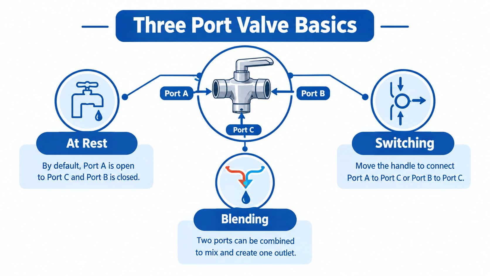
Think of a valve as a junction with controlled passages. A kitchen tap gives a simple analogy: the pipe openings are the ports, while the handle changes which routes are open. With a valve, though, you must also know which port is the inlet, which is the outlet and what the internal element does when the actuator is at rest.
Port labels aren't universal. A hydraulic drawing might use P for pressure, T for tank and A for an actuator line. A heating valve may use AB for the common connection and A and B for its two outlets. On a process valve, the manufacturer's flow diagram may define the ports differently. Always read the markings and documentation for the actual component.
Decode the notation
The shorthand 3/2 means three ports and two discrete valve positions. 3/3 means three ports and three positions. The notation describes the layout, not a particular manufacturer, application or flow pattern. To understand what a specific valve does, read the symbol in each position and check the port labels.
A normally closed valve blocks the specified flow path at rest, then opens it when actuated. That may suit a circuit where flow should stop when the control signal is absent. A normally open valve allows flow at rest and closes the path when actuated. The terms apply to the defined route, so check the symbol rather than assuming the whole valve is open or shut.
A mid-position valve has a central position between its two actuated positions. Depending on its internal design, that position might block a path or connect ports to allow shared flow. Don't assume every three-position valve has the same neutral behaviour.
Connect the symbol to the task
For a single-acting cylinder, a 3/2 valve can connect pressure to the actuator in one position and provide a return path in the other, depending on its design. In a heating circuit, a mid-position valve can allow boiler flow to serve space heating and hot water simultaneously. The port count alone doesn't tell you which behaviour you'll get.
A valve can also blend two incoming fluids into one outlet, but that's a different function from switching a cylinder line between pressure and return. Before choosing a component, trace each route from its source to its destination and establish which routes must be open in every operating state.
Comparing the Three Common Types of Three Port Valve
Three products can all be described as “three port valves” yet behave very differently. The distinction becomes clearer when you compare what each device connects, how it's controlled and what you should verify before installation.
| Type | Typical ports | Fail position | Typical use |
|---|---|---|---|
| Heating mid-position valve | AB is the common inlet, A serves space heating and B serves the hot-water cylinder | Depends on the actuator and wiring arrangement. Confirm from the component documentation | UK Y-Plan domestic heating, with heating-only, hot-water-only and shared-flow operation |
| Hydraulic directional valve | Often P for pressure, A for an actuator and T for tank, though arrangements vary | Depends on spool, spring and actuator design | Directing fluid to a cylinder or motor, or providing a return path |
| Mixing or diverting valve | Commonly a common connection and two branches, with exact labels set by the manufacturer | Depends on valve pattern and actuator arrangement | Mixing incoming flows or selecting between outlets |
| Switched-inertance valve system | A high-speed switching valve works with an inertance tube and accumulator | System response depends on the design and controls | Research into controlling hydraulic pressure or flow using rapid digital switching |
Where the meanings diverge
In UK domestic heating, the three-port motorised valve became a defining part of the Y-Plan system and is historically associated with Honeywell's development. It's widely found in installations dating from the 1970s and 1980s. Earlier W-Plan diverter arrangements generally prioritised one circuit rather than providing the same simultaneous-flow function. This legacy means a replacement job may involve older valve and actuator wiring arrangements, so identifying the original control strategy is as important as matching the pipe connections. Background on UK motorised valves and Y-Plan systems
A hydraulic directional valve uses its internal spool or other control element to connect circuit paths. Its function depends on the symbol and the manufacturer's port arrangement. A process-style mixing or diverting valve may instead use a rotating element, such as a ball, with its own permitted flow patterns. If the application calls for a rotary valve, review the available three-way ball valve information against the manufacturer's port diagram rather than treating it as a spool-valve substitute.
Switched-inertance systems are another meaning altogether. They use rapid switching as part of a system that includes an inertance tube and accumulator, rather than behaving like a conventional directional valve. That makes the valve, drive and surrounding hydraulic circuit a coupled design.
The substitution mistake to avoid
The common trap is replacing a heating mid-position valve with a diverter, or the other way round, because both have three connections. A diverter that doesn't provide the required shared-flow state can disrupt the intended operation. Check the programmer, thermostats, wiring logic and valve specification before fitting the replacement.
Reading Schematic Symbols for Three Port Valves
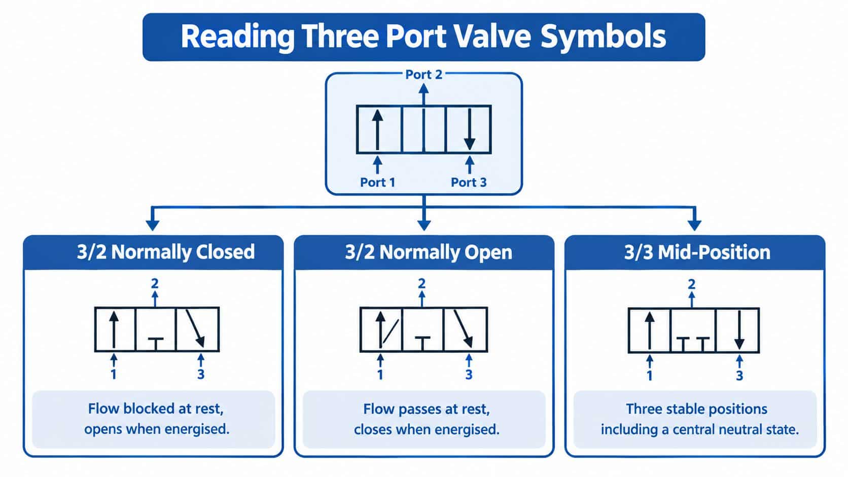
A hydraulic symbol shows how the valve connects the circuit in its different positions. Read it as a set of operating states, not as a picture of the valve body. Each square represents a position; lines and arrows show possible connections, and a capped line indicates a blocked port in that state.
Read the boxes and connections
For a 3/2 normally closed symbol, start with the box beside the spring or rest indicator. Follow the lines to see whether the relevant route is blocked at rest. Then move to the actuated position and check which ports are connected.
A 3/2 normally open symbol shows the opposite default for its defined route: flow can pass at rest, with the connection changing when actuated. Don't rely on “open” and “closed” as descriptions of the whole circuit. Trace the path between named ports.
A 3/3 mid-position symbol has three boxes, one for each position. The centre box matters: it shows what happens when the valve is in its central state. Depending on the design, paths may be blocked or connected. Check the actual centre-state symbol rather than assuming it is a universal neutral arrangement.
For a plain-language guide to the markings commonly used in hydraulic diagrams, see the hydraulic circuit symbol reference.
Don't mistake an arrow for a command
An arrow indicates a possible direction of flow through a connection. It doesn't, by itself, mean that a motor or solenoid is powering the fluid. The symbol may also show a spring return, a solenoid, a lever or pilot actuation. Those marks tell you how the valve changes position, while the boxes describe the resulting flow paths.
Before fitting a valve, check the following against the physical component:
- Port identity: Match the drawing labels to the markings on the valve body.
- Flow direction: Check any cast arrows and confirm they agree with the circuit diagram.
- Rest and centre state: Verify what happens when the valve is unpowered or centred.
- Actuation: Confirm the solenoid, spring, pilot or manual operator matches the control system.
- Connection pattern: Check every required route, including which ports are blocked in each state.
If a symbol or port label doesn't match the part in front of you, stop and resolve the discrepancy before connecting pipework. A valve can fit physically and still be wrong for the circuit.
Choosing the Right Three Port Valve for the Job
Start with the circuit's job, then specify the valve. Don't begin with a familiar product name or a body that looks similar to the one being replaced.
Work through four decisions
Is the valve switching flow or blending it? A selector that sends one supply to one of two destinations needs a different port pattern from a valve that combines two feeds. For a ball valve, inspect the manufacturer's flow diagram to confirm whether its internal pattern supports the required route.
What must happen if the actuator or supply fails? Specify the required de-energised or de-pressurised state. Confirm whether the valve returns under spring force, stays in its last position or behaves another way. Then check that the surrounding machine remains safe in that state.
Can the third port safely block or dead-head? Trace the route in every position and consider what happens to trapped pressure, a pump's flow and any connected load. If a position could block a live supply, establish whether the circuit needs pressure relief or another protective arrangement.
Does the circuit need a separate load-control device? A directional valve doesn't automatically replace a relief valve, counterbalance valve or load-holding arrangement. Select those components from the circuit's safety and load requirements, not from the number of valve ports.
Put the details on the specification
For an electrically modulated hydraulic control valve, BS ISO 10770-2:2012 provides a test-method basis for evaluating performance such as flow versus command, pressure drop, hysteresis, leakage and dynamic response. For screw-in cartridge designs, BS ISO 7789:2007 covers cavity dimensions for two-, three- and four-port cartridges. These references help engineers test the valve and verify compatibility; they don't remove the need to specify the actual circuit requirements. Fluid power standards and valve test references
State the port connections, rated pressure and flow, allowable pressure differential, actuator signal and required failure state. For a cartridge valve, verify the complete valve-cavity interface rather than just the thread or nominal bore. A component that screws into a manifold can still have the wrong dimensions or flow behaviour.
A tractor-loader joystick circuit, for example, needs a valve selected for the required actuator paths and the machine's load-control strategy. A Y-Plan heating replacement instead needs the correct mid-position function and wiring compatibility. You can review three-way solenoid valve options when an electrically operated component is required, but confirm the circuit and operating states before selecting a model.
An illustrative switched-inertance research system from the University of Bath demonstrated a switching time of 0.5 ms while handling 55 L/min at a 10 bar pressure drop. A later experimentally validated converter study reported 46% average steady-state efficiency against 76% simulated efficiency under its tested variable-load control case. These results show why rapid switching alone doesn't guarantee the expected efficiency; commissioning must measure the actual system. Research on switched-inertance hydraulic systems
The video below is embedded in a responsive frame. Check it at the published page width so its controls, diagrams and proportions display correctly.
Installing, Commissioning and Diagnosing Three Port Valves
A new valve won't fix contamination upstream, trapped air or incorrect plumbing. Before fitting a replacement, confirm the circuit and prepare the pipework. Manufacturer instructions commonly call for flushing before installation, checking flow arrows, providing isolation and allowing for maintenance access. Follow the instructions for the specific valve and system.
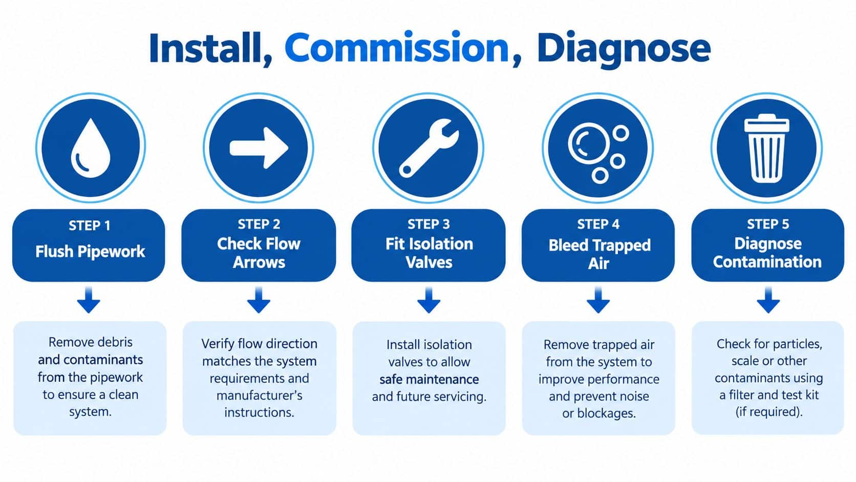
Use a safe test sequence
Isolate and depressurise the circuit before loosening a connection or removing the valve. Hydraulic energy can remain in a system after shutdown, so use the machine's safe isolation procedure and confirm pressure has been relieved. For maintenance, isolate all three ports where the circuit design allows and follow the manufacturer's servicing instructions.
Then work through the fault in a controlled order:
- Verify the schematic and port identity. Check that the installed valve and connections match the intended circuit.
- Inspect fluid cleanliness and filtration. Look for contamination or a filter condition that could restrict or jam the spool.
- Check pilot or control pressure. An actuator may fail to shift because its control supply is wrong, not because the valve body is damaged.
- Test movement and leakage. Confirm spool or actuator travel and check whether fluid is crossing between ports when it shouldn't.
- Replace or rebuild only after ruling out upstream causes. Record the test results so the next technician can see what was checked.
A contamination-led diagnosis
Suppose a cylinder moves unpredictably after pipework maintenance. A technician might suspect the three-port valve because the symptom appears when the valve changes position. But debris introduced during the work could interfere with spool movement, while trapped air or a control-pressure issue could also produce erratic operation.
The technician should isolate and depressurise the circuit, verify the port layout, then inspect the fluid and filter before condemning the valve. Contamination has been linked to 30% of fluid-power breakdowns, with an average UK business cost of £15,000 per incident, as reported in the MLC discussion of fluid-induced valve failures. That context makes cleanliness checks part of fault-finding, not an optional extra.
After installation, commission the valve in a controlled sequence and check every intended operating state. During planned maintenance, inspect for gland leakage and confirm that isolation arrangements remain usable. A valve should be replaced only when its condition or test results justify it, not because it was the first suspect.
A Practical Checklist and Where to Get Help
Use this checklist before ordering, fitting or fault-finding a valve:
- Confirm the function: Identify whether the valve switches, mixes, diverts or controls a heating circuit.
- Trace each port: Match the body markings to the schematic and the actual pipework.
- Verify every position: Check the rest state, actuated states and any mid-position behaviour.
- Specify the failure state: Record what the machine must do when electrical or hydraulic power is lost.
- Check the interface: Confirm pressure and flow requirements, connections and, for cartridge valves, cavity compatibility.
- Prepare the circuit: Isolate safely, flush where required and check cleanliness before fitting.
- Commission methodically: Test the intended paths, leakage and actuator movement, then record the results.
The same checklist supports both selection and diagnosis. If a valve appears to fail, confirm the circuit, cleanliness and control conditions before replacing it. If you're specifying a new part, keep the required port connections and failure state with the procurement notes so the next person can verify the choice.
A UK supplier can help check application details, cross-references and hard-to-find components. For clear accessibility, keep diagrams labelled consistently with the surrounding text, and make sure any instructional video has usable captions and displays correctly at the page width.
MA Hydraulics Ltd supplies hydraulic valves and related components for mobile and industrial applications, and can help with component selection, cross-references and hard-to-find parts. Phone 01724 279508 today or send a message through the MA Hydraulics contact page; for application advice and hydraulic component support, visit MA Hydraulics Ltd.
