
You've got a machine down, the old hydraulic motor is worn, and the replacement appears to be a straightforward swap. Then the questions start. Will the existing pump deliver the required speed? Is the shaft compatible? Can the motor tolerate reverse drive, braking loads and case-drain pressure? A catalogue displacement alone won't answer those questions.
This gear motor hydraulic guide approaches selection as a system decision. The useful comparison isn't one brand against another. It's whether the motor's displacement, pressure capability, interfaces, cleanliness requirement and protection arrangements suit the duty cycle. That matters in the UK, where the hydraulics market is mature but still expanding. The UK market was valued at about $2.46 billion in 2025 and is projected to reach about $2.73 billion by 2030, a projected 2.1% CAGR according to MarketsandMarkets' UK hydraulics market data. For procurement teams, that points to steady replacement, retrofit and efficiency demand rather than a short-lived spike.
How a Hydraulic Gear Motor Works in a System
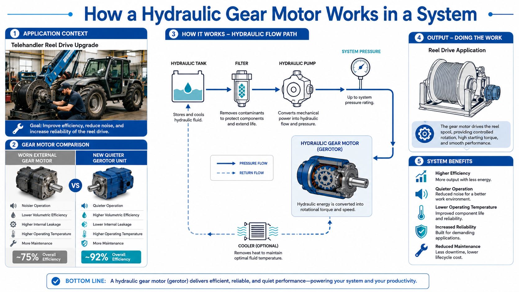
A telehandler's reel drive is a familiar example. The external gear motor has developed leakage and noise, and a quieter gerotor unit looks attractive. Before approving the change, the design engineer needs to confirm rotation, shaft loading, pressure, flow, drain arrangements and starting behaviour. Replacing the motor without checking the circuit can move the failure to another component.
A hydraulic gear motor is a fixed-displacement rotary actuator. It converts hydraulic flow and pressure into shaft rotation, producing mechanical torque and angular displacement. The pump supplies fluid, the motor turns that fluid energy into rotary output, and the reservoir receives the returning oil through the return path.
In an external gear motor, pressurised oil enters the inlet side and fills the spaces between meshing gear teeth and the housing. The gears carry the trapped oil around the outside of the gear set, rather than through the meshing zone, and the outlet restriction creates the pressure difference that forces the shaft to turn. The motor's output depends on the relationship between flow, displacement and pressure drop.
Three common constructions
- External gear motors use two externally meshing gears. They're compact, relatively simple and well suited to many high-speed mobile and industrial duties.
- Internal gear motors use an internal gear arrangement. The geometry can support different packaging and operating characteristics, depending on the series.
- Gerotor, or orbital, motors use an inner rotor and outer ring arrangement. They're often considered where smooth low-speed operation, compact installation or quieter running matters.
The motor doesn't work in isolation. The pump establishes available flow, the relief valve limits system pressure, the reservoir and return line manage heat and contamination, and the case drain controls pressure around the shaft seal and internal clearances. A motor that appears correctly rated on paper can still fail if the return path is restricted or the relief setting allows excessive loading.
Practical rule: Treat the motor, pump, valves, hoses, reservoir and protection devices as one power circuit. A replacement is only suitable when the complete circuit remains within its operating limits.
Unidirectional and Reversible Gear Motors by Group
The first decision is the direction of rotation. A unidirectional motor is intended to run in one normal direction. Some catalogue descriptions use “bi-directional” for a unidirectional motor fitted with integral cross-over relief valves, allowing pressure to be managed during reversal or transient loading. That arrangement isn't the same as a reversible motor.
A fully reversible motor changes rotation when the pressure and return ports are swapped. It's the more appropriate choice where the machine regularly reverses, brakes a moving load, or experiences overrunning torque. The circuit still needs correctly selected relief and anti-cavitation protection, because reversing the ports doesn't remove the pressure transients created by the load.
Group classification gives a useful first filter, but it isn't a universal performance standard. Confirm the actual displacement and pressure ratings in the manufacturer's datasheet.
| Group | Typical displacement (cc/rev) | Common configurations | Typical duty |
|---|---|---|---|
| Group 0 | Up to about 5 | Compact unidirectional units, some reversible variants | Low-torque ancillaries and compact mechanisms |
| Group 1 | About 5 to 20 | Unidirectional and reversible | Materials handling, compact industrial drives and auxiliary functions |
| Group 2 | Roughly 20 to 50 | Unidirectional and reversible | General mobile plant, agricultural drives and conveyor duties |
| Group 3 | From about 50 upward | Heavy-duty unidirectional and reversible options | Higher-flow mobile equipment and demanding industrial drives |
UK suppliers including Bosch Rexroth, Parker and Danfoss Power Solutions offer products across these broad groupings. Group 2 and Group 3 units are common workhorses on mobile plant because they provide a practical balance between torque, flow demand and package size.
UK supply trends also matter when a machine needs a fast replacement. The UK industrial gearbox and gear motors market recorded import-trend growth of 15.22% from 2023 to 2024, while its 2020 to 2024 CAGR was 5.72%, as reported in 6Wresearch's UK industrial gearbox and gear motors market overview. That increase reflects the importance of checking equivalent imported units carefully, rather than assuming that a familiar group label guarantees interchangeability.
Torque, Speed, Displacement and Pressure Specifications
A UK datasheet usually gives four headline values. Read them as connected specifications, not separate marketing figures.
Torque is the turning force available at the shaft, expressed in Nm. The useful value depends on pressure drop across the motor and its displacement, then falls below the theoretical figure because of mechanical and volumetric losses. A motor exposed to inlet pressure without sufficient outlet control can also behave very differently from its catalogue test point.
Speed is normally stated in revolutions per minute. It's governed by flow and displacement, but the listed speed rating is generally a continuous operating limit, not permission to run at a short-cycle peak indefinitely. Check the duty cycle, oil temperature, bearing load and manufacturer's permitted speed range.
Displacement is the fixed geometric volume moved per shaft revolution, stated in cc/rev or cm³/rev. Increasing displacement normally gives more torque at a given pressure, while demanding more flow for the same speed. It's the most useful initial sizing handle, but it won't confirm that the motor can tolerate the actual load.
Pressure needs careful reading. Datasheets commonly distinguish maximum continuous pressure from intermittent or peak pressure, both quoted in bar. A peak figure may apply only for a limited duration and at a defined speed, temperature and case-pressure condition.
Read the test basis, not only the nameplate
The UK standards index for pumps and motors lists BS ISO 4409:2019 for steady-state performance testing, BS ISO 8426-2 for derived displacement, BS ISO 10767-3 for pressure ripple measurement, BS 7275-3 for motor characteristics at constant flow and torque, and BS ISO 4392-1 for low-speed, constant-pressure motor characterisation. These references are visible through the UK-facing pumps and motors standards listing.
That framework is more useful than comparing nameplate pressure alone. Ask whether competing Bosch Rexroth, Parker, Danfoss, Eaton or Casappa figures were established using comparable displacement, efficiency, ripple and operating-point methods. The MA Hydraulics hydraulic pumps and motors range is a sensible starting point when you need to match those specifications to an available component.
Case-drain backpressure is a frequent source of trouble. Catalogue ratings assume a permitted pressure around the motor case and shaft seal. If the drain line, return filter or cooler creates excessive resistance, the seal can extrude or leak even though the main pressure remains within the headline rating.
Sizing Calculations and Real-World Efficiency
Three calculations establish whether the proposed motor is in the right area. They're useful for screening candidates, but final approval still requires the manufacturer's rating tables and duty limits.
For speed, use:
Q = Vg × n / 1000
Here, Q is flow in litres per minute, Vg is displacement in cc/rev and n is speed in rpm. A 19 cc/rev Group 2 motor supplied with 30 l/min gives a theoretical speed of about 1,570 rpm, before volumetric slip is considered. That is a screening calculation, not a guaranteed shaft speed.
For theoretical torque, use:
T = Vg × Δp / 62.8
With 19 cc/rev and a pressure drop of 175 bar, the theoretical torque is near 53 Nm. Actual running torque will be lower because leakage, friction and mechanical drag consume part of the available hydraulic energy.
Hydraulic power can then be expressed as:
P = T × n / 9550
Use the actual shaft torque and speed when estimating mechanical output. A pump delivering the required flow and pressure still won't provide the same power at the shaft after losses in the pump, motor, valves, hoses, fittings and cooler.
Why brochure efficiency can mislead
UK-facing technical material gives a useful range for interpretation. One UK reference lists gear motors at about 80% to 90% running efficiency, while another supplier resource gives typical gear-pump efficiency of 80% to 88%, with efficiency declining as wear increases. A separate UK oil-cooler guide explains that a pump driving a gear motor can reach only roughly 72% best-case efficiency before valve and conductor losses are included. Those figures appear in Hydraulic Pressures' oil-cooler sizing guidance.
The practical question is therefore not “What's the motor's catalogue efficiency?” It's “What energy reaches the shaft across the actual duty cycle?” Include cold-start viscosity, hose length, valve pressure drop, return restriction, load variation and cooling requirements.
Selection advice: A cheaper motor can become the expensive option if its lower efficiency creates more heat, forces additional cooling and increases the operating load on the pump.
For a more detailed application check, use the MA Hydraulics guide to sizing a hydraulic motor. Ask suppliers to compare figures on the same test basis, including the relevant ISO performance method, instead of placing unlike catalogue values in the same spreadsheet.
Mounting, Shaft and Port Interface Options
A motor can have the correct displacement and still be unusable as a replacement. The mechanical interfaces must match the existing drivetrain, or the cost of adapters, couplings and altered pipework can outweigh the component saving.
Common mounting choices include SAE-A, SAE-B and SAE-C two-bolt or four-bolt flanges, normally associated with ISO 3019-1 and SAE J744 arrangements. Square four-bolt flanges and European or CEE pad mounts also appear frequently on UK mobile equipment. Larger Group 3 installations may use an SAE four-bolt Code 61 flange where the pipe connection needs a flanged interface.
Shaft selection deserves the same attention. Parallel keyed shafts are common, with key dimensions referenced to BS 46 or ISO 773. Splined options include SAE 6B, 10B and 13B arrangements under ISO 3019-2. Tapered shafts may use a Woodruff key, or a nut and washer arrangement where the coupling needs secure retention under higher torque.
Measure before ordering
Send the supplier a drawing or measured sketch that identifies:
- Pilot diameter and bolt circle, including the number and size of mounting holes.
- Shaft diameter, length and keyway, including keyway width and depth.
- Port type and orientation, such as BSPP under ISO 228 or SAE O-ring boss under ISO 11926.
- Drain-port position, with the motor mounted in its actual orientation.
- Coupling and side-load details, particularly where a sprocket, pulley or gearbox sits directly on the shaft.
The drain port must remain correctly positioned relative to the case fill and the manufacturer's installation instructions. An incorrectly oriented motor can trap air, starve internal surfaces or allow the case to drain during shutdown.
For brake-equipped drives, the motor and brake release circuit need to be assessed together. The MA Hydraulics hydraulic motors with brake range provides a useful reference point, but the final choice still depends on holding torque, release pressure, shaft loading and stopping behaviour.
Typical Applications Across Mobile and Industrial Use
Application determines which specification matters most. The same Group 2 label can describe a suitable auger motor, an unsuitable conveyor drive, or a poor choice for a reversing reel.
Agriculture
Feeder and mixer augers commonly need low-speed, high-torque reversible operation. Select for continuous-duty pressure, starting torque, bearing capacity and resistance to side loading. If the auger can jam or overrun, check the relief and anti-cavitation arrangement rather than relying on the motor's maximum pressure figure.
Materials handling
Forklift attachments, pallet-truck pump and motor combinations, and compact conveyor drives often favour Group 1 or Group 2 units. Packaging envelope, mounting compatibility and purchase cost can be decisive, but a low-cost motor with poor shaft support won't cope with a drive chain or pulley that imposes excessive radial load.
Mobile plant
Telehandler reel drives, compact sweeper brooms and other mobile functions commonly use reversible Group 2 motors. Thermal cycling, shock loading, contamination and case-drain protection are more important than a high short-duration catalogue speed. A unit that starts smoothly and survives repeated directional changes can be more valuable than one with a higher headline peak rating.
Industrial automation
Machine-tool saw drives, plastic injection mould ejection systems and indexing tables generally need repeatable speed and predictable torque under changing loads. Group 1 and smaller Group 2 unidirectional motors can suit these duties when the control circuit manages flow consistently.
Across all four areas, shortlist by required displacement, operating speed, continuous pressure and duty cycle. Peak values can help with transient assessment, but they shouldn't define a continuous application.
Maintenance, Fluid Cleanliness and Common Faults
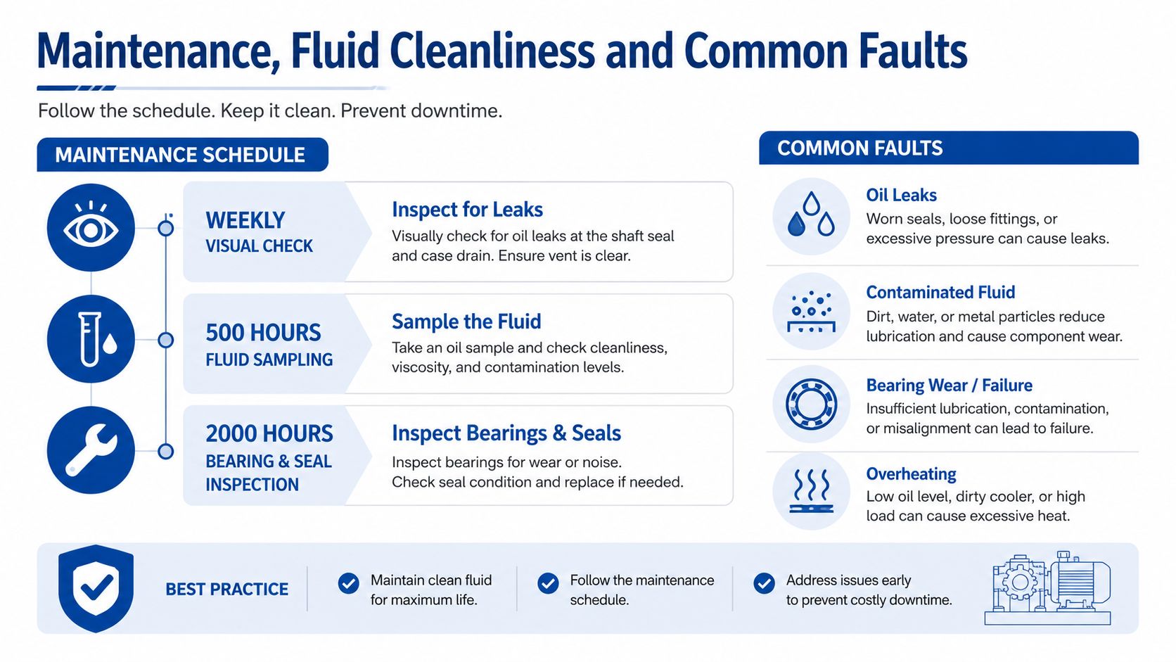
Maintenance should follow the machine's actual operating exposure. A practical routine starts with a weekly visual inspection of the shaft seal, mounting face, ports and case-drain line. Fluid sampling at 500 operating hours and bearing and seal inspection at 2,000 operating hours can provide useful planning points, but dusty, wet or heavily loaded equipment may need a more frequent programme.
The Marzocchi GHM UK catalogue specifies contamination control at or below ISO 4406 class 18/15 for the listed units. The same catalogue advises pre-filtering fresh fluid where necessary and disconnecting the supply-pump drain during start-up to bleed air from the circuit. Follow the exact motor manual if its cleanliness or commissioning requirement differs.
Match symptoms to causes
- Speed falls progressively under load: Internal leakage may have increased through wear. Check motor case drain flow, fluid condition and relief-valve operation before condemning the unit.
- Case-drain flow rises: Worn gear clearances, damaged bushings or excessive case pressure can be responsible. Compare measured flow with the manufacturer's limit.
- The shaft seal weeps externally: Check case-drain restriction, shaft alignment, shaft surface condition and seal compatibility.
- Noise increases as the oil heats: Lower viscosity can increase internal leakage and reduce lubrication quality. Verify fluid grade, cooler performance and operating temperature rather than tightening fittings.
The UK Marzocchi ALM catalogue gives group-specific displacement ranges, including ALM1 from 1.4 to 13.8 cc/rev, ALM2 from 4.5 to 35.2 cc/rev, and ALM3 from 20 to 87 cc/rev. It also notes that applications with counterpressure above 6 bar require technical-office guidance, as shown in the ALM series catalogue.
Filter selection should support the required ISO 4406 cleanliness code. Check element construction and beta-ratio performance against the circuit's contamination risk, rather than over-specifying a filter without considering pressure drop, bypass behaviour and service availability.
Backpressure, Drainage and Protection Decisions
A catalogue-listed motor isn't automatically a safe drop-in replacement. The three decisions most often missed are case-drain pressure, drain routing and protection against pressure or thermal events.
First, confirm the maximum permitted case-drain backpressure. Second, route the drain directly to tank as required by the manufacturer, avoiding a return connection that can pressurise the case during filter loading or cold oil conditions. Third, check whether the inlet needs anti-cavitation protection, especially when the load can overrun the motor or the machine reverses under braking.
The consequence of excessive case pressure can be shaft-seal failure. Poor drainage can also trap air or raise internal pressure. Inadequate relief or anti-cavitation protection can cause gear-tooth scuffing, shock loading and damage during cold starts or sudden load release.
Before approving a replacement, make these checks mandatory:
- Drain line: Confirm diameter, routing, termination and permitted backpressure.
- Relief setting: Compare the circuit setting with the motor's maximum continuous pressure and the machine's actual load.
- Return filtration: Confirm that the filter and bypass arrangement support the specified cleanliness target.
- Reverse and braking duty: Establish whether the motor is reversible and whether cross-over reliefs or anti-cavitation valves are required.
- Thermal behaviour: Check heat rejection at the duty cycle, not only during a short commissioning run.
A UK supplier notes that some gear-motor series require technical-office contact when counterpressure exceeds 6 bar, reinforcing the point that backpressure is a design limit, not a minor installation detail. The relevant guidance is available from MA Hydraulics on gearbox motors.
Quick-Reference Specification Table
The table below is a shortlisting aid, not a substitute for a manufacturer's datasheet. Exact displacement, pressure, torque and direction options vary by model, shaft, bearing arrangement and operating conditions. Confirm every figure before purchase.
| Group | Displacement (cc/rev) | Max continuous pressure (bar) | Peak torque (Nm) | Direction options | Typical application |
|---|---|---|---|---|---|
| Group 0 | Up to about 5 | Confirm by model | Confirm by model | Unidirectional, selected reversible units | Compact ancillaries and light mechanisms |
| Group 1 | About 5 to 20 | Confirm by model | Confirm by model | Unidirectional and reversible | Materials handling and light industrial drives |
| Group 2 | Roughly 20 to 50 | Confirm by model | Confirm by model | Unidirectional and reversible | Agricultural equipment, mobile plant and conveyors |
| Group 3 | From about 50 upward | Confirm by model | Confirm by model | Unidirectional and reversible options | Higher-flow mobile plant and demanding industrial duties |
UK-stocked families from Bosch Rexroth, Parker, Danfoss, Eaton and Casappa can occupy overlapping group and displacement bands. The correct comparison remains the complete operating envelope, including speed, pressure, shaft load, mounting and case-drain restrictions.
UK Standards, Cross-References and Next Steps
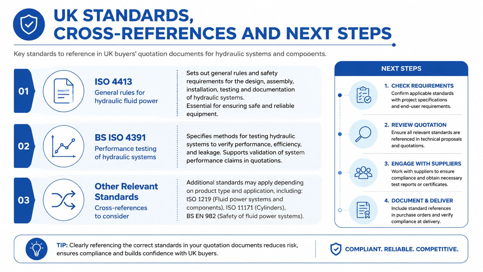
Quotation documents should identify the standards used for the complete hydraulic installation, not only the motor. ISO 4413 provides general rules for hydraulic fluid power systems, while BS ISO 4391 addresses performance testing. Flange, shaft and port interfaces also need checking against the relevant ISO, SAE and CETOP arrangements before a supplier treats a unit as equivalent.
Part-number families can help procurement create an initial shortlist. Bosch Rexroth AZMF, Parker GHP, Danfoss OMM and EATON Char-Lynn references may point towards different construction types and displacement bands, so the code alone isn't enough for interchangeability. European OEM stock may offer a different availability profile from Chinese-sourced units, where lead time and documentation need checking before a machine-down replacement is promised.
Send a technical desk the operating pressure, flow, speed, duty cycle, fluid type, mounting sketch, shaft dimensions, rotation requirements and case-drain details. That information gives the selector enough context to recommend a functional equivalent rather than another motor that merely fits the catalogue group.
MA Hydraulics Ltd can help select and supply hydraulic gear motors, including Vivoil unidirectional and reversible units across Groups 0 to 3, for OEM, agricultural, mobile and industrial applications. Visit MA Hydraulics Ltd to discuss a replacement, cross-reference or complete hydraulic solution, phone 01724 279508 today, or send a message.
