
System integration is the process of joining separate hardware and software systems so they share data, signals, and processes as one working infrastructure. In a hydraulic plant, that might mean a power pack, a PLC, and a maintenance platform all exchanging information instead of each sitting in its own silo.
You can usually spot the need for it the moment a technician has to check one screen for pump pressure, another for alarm history, and a third for planned maintenance. That is not one system. It is a set of disconnected parts, and someone has to bridge the gaps every time a fault, handover, or production change happens.
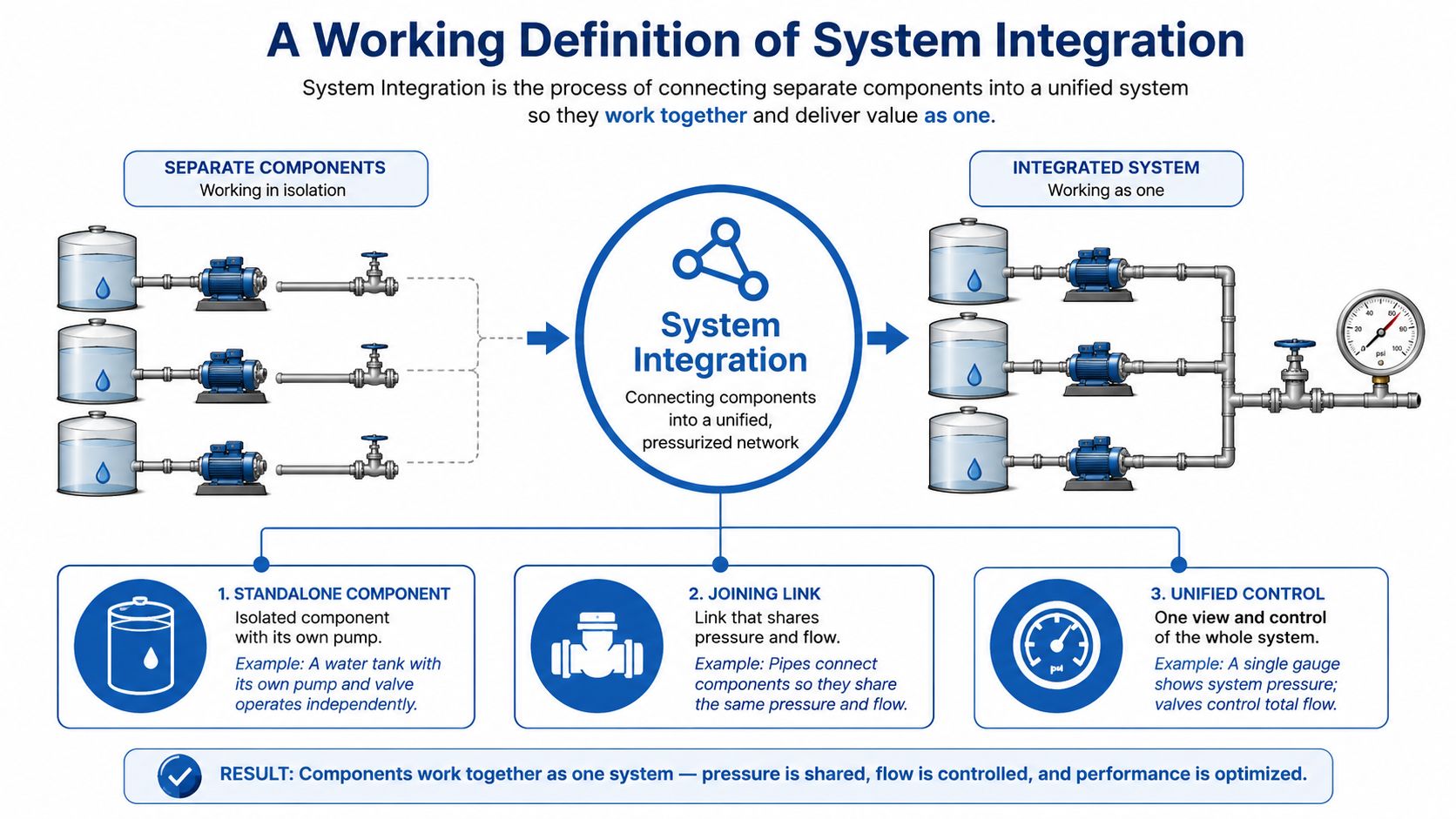
A Working Definition of System Integration
A good working definition starts with a shop-floor example. Say you have a hydraulic power pack with a gear pump, CETOP valves, sensors, and a separate PLC, but the maintenance team still logs faults manually and the ERP system never sees the service events until later. The equipment works, but it works in pieces.
System integration is the act of joining those separate hardware and software systems so they share information and processes as one cohesive setup. In practice, that means the pump unit, the controller, the alarms, the service records, and the business systems are connected well enough that the right data moves to the right place without manual re-entry.
That distinction matters because integration is not just about wiring two products together. In systems engineering, it is an iterative verification and validation process that assembles implemented elements into a complete or partial configuration and checks the correctness of static and dynamic interfaces before final validation and transition to use or production, which is why interface control documents and acceptance tests matter so much in hydraulic builds SEBoK system integration.
Why UK teams treat it as a core capability
For UK manufacturers and public services, integration has become a practical requirement rather than a nice extra. Government digital policy has pushed departments toward joined-up delivery, because simplifying services and improving satisfaction depends on connecting back-end systems, data, and user journeys rather than leaving them fragmented AltexSoft on system integration. GOV.UK’s shared platforms and standardised service design also show how reuse cuts duplication in login, payments, notifications, and publishing AltexSoft on system integration.
In industry, the same logic applies to pumps, valves, ERP, CMMS, and SCADA. If the controller knows the machine state, and the maintenance platform knows the running hours, and procurement can see the service trend, then decisions are made from one version of the truth.
Practical rule: if a person has to copy data from one system into another to keep the machine running, the systems are not integrated yet.
For a plain example of how integration is described in connected software environments, the overview on Lynkro.io integrations is useful because it frames integration as a joined workflow rather than a stack of isolated tools.
Common Integration Approaches and Architectures
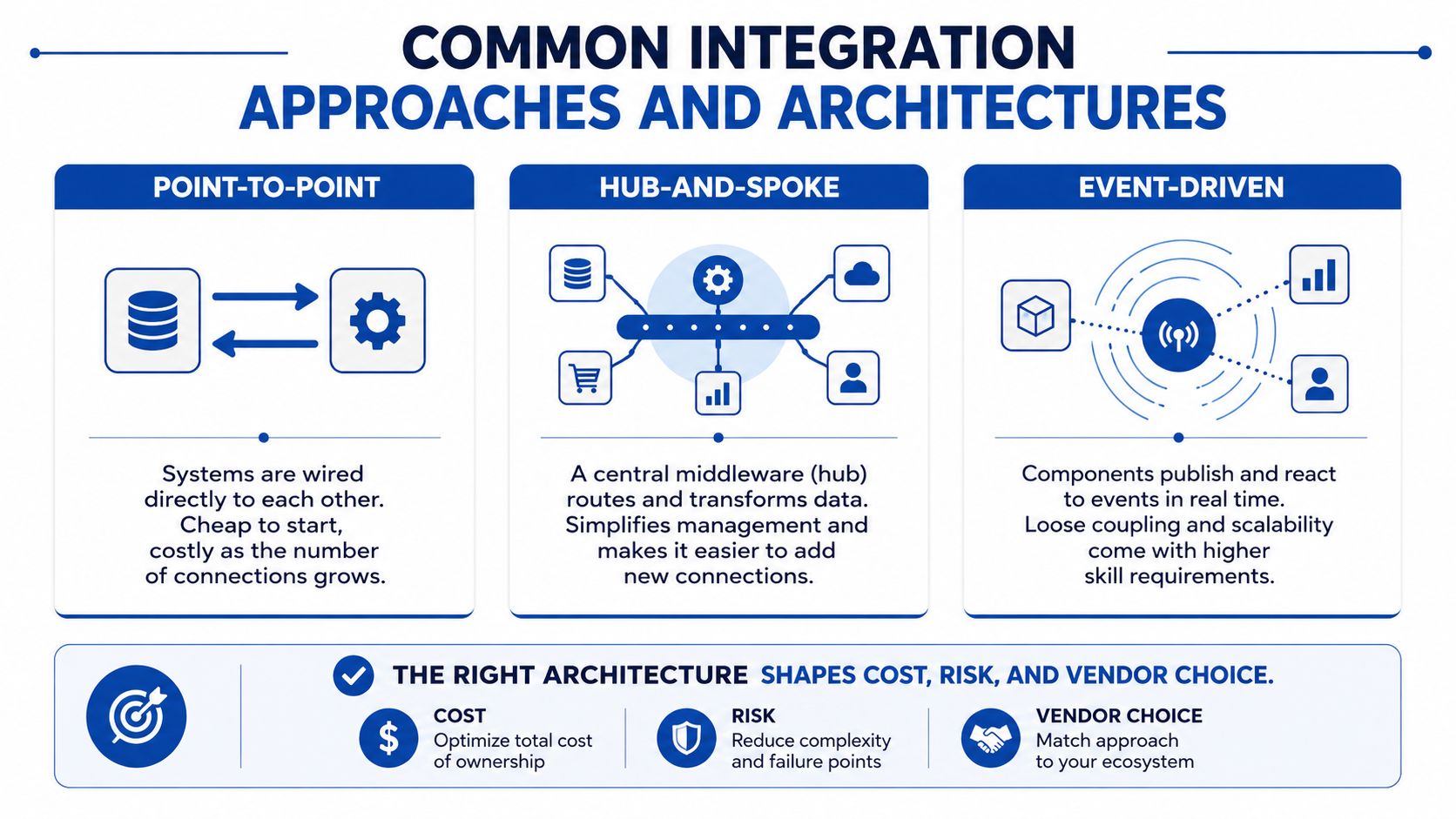
A hydraulic system does not fail or succeed because it is “integrated” in the abstract, it succeeds or fails because the chosen architecture matches the machine’s behaviour, signal timing, and maintenance needs. A small mobile unit with one controller and one telemetry feed can tolerate a direct link. A production line with PLCs, valve islands, pressure monitoring, ERP, and service records needs a cleaner structure, or fault-finding becomes slow and expensive.
Point-to-point links suit small, simple jobs
Point-to-point integration is a direct connection between two systems. In hydraulic terms, that might be a PLC sending a status signal straight to a telemetry unit, or a machine controller pushing one alarm feed into a maintenance app. It is easy to understand, and for a narrow task it can be the right choice.
The limit shows up as soon as the estate grows. Each extra connection creates another path to maintain, and troubleshooting becomes harder when no one can see how the signals relate to each other.
Middleware gives structure, but adds another layer
An enterprise service bus or other middleware layer sits between systems and routes data between them. That suits larger estates where a PLC, ERP, and service database all need to exchange structured messages. It gives you one place to manage transformations, interface rules, and message handling, which helps when the estate already has mixed equipment and older software.
The trade-off is another layer to design and support. If the project only needs a few controlled data exchanges, the middleware can add overhead without solving a real hydraulic or maintenance problem.
APIs give cleaner links between modern systems
API-led integration is common where software products already expose defined interfaces. SolarWinds describes system integration as linking subsystems so they can exchange data with each other, including connections inside the organisation and to external SaaS providers SolarWinds on system integration. For a hydraulic OEM, that can mean a PLC or edge gateway pushing pressure and temperature data into a cloud platform through APIs, or a service app pulling alarm history from a control layer.
That same discipline matters in software delivery too. The idea behind CI for SaaS teams is similar, because each interface has to keep working while the surrounding system changes.
Hybrid models fit real machines
Most industrial installations end up hybrid. OT systems such as PLCs, HMIs, and SCADA need predictable timing and tight control, while ERP, CMMS, and analytics platforms care more about records, workflows, and reporting. A hybrid design lets the machine side keep its hard real-time behaviour while business systems receive the data they need in a controlled way.
For hydraulic projects, that usually means deciding where the signal should stop being local machine control and start becoming information for planning, service, or procurement. A pressure switch that only protects the pump belongs in the control layer. A pressure trend that feeds maintenance planning belongs in the reporting layer, often supported by pressure monitoring systems and the wider application engineering support needed to match the hardware to the use case.
In practice: use the simplest architecture that meets the operating need, then add layers only when the project genuinely needs them.
Key Components of an Integrated Hydraulic and Industrial System
A shop floor integration project usually starts with hardware, not software. The PLC, HMI, or ERP may get the attention, but the component chosen at the machine end decides what can be measured, what can be controlled, and how hard the system will be to service later.
The hydraulic layer
At the base are the parts that generate and control power. That includes gear pumps, gear motors, power packs, mini power packs, CETOP directional valves, proportional valves, modular valves, inline valves, flow dividers, filters, manifolds, and sensors. A pump or valve block on its own is just a component. Put it into a machine circuit, and it becomes part of a controlled flow path with feedback, fault detection, and operating logic.
Selection here should follow the machine duty, the available space, and the maintenance model. A compact mini power pack may suit a mobile unit with limited room and intermittent duty, while a larger power pack may be better where heat rejection, service access, and continuous operation matter more. The same applies to valve choice. A CETOP stack may be easy to standardise, but a manifold with integrated sensing can reduce hoses and joints if the circuit needs tighter packaging and fewer leak points.
For a procurement manager, the question is not only whether the component meets pressure or flow requirements. It is whether the unit has the right interfaces for pressure monitoring, switching signals, diagnostics, and service access. For a design engineer, the circuit layout and the electrical interface have to be considered together, because a good hydraulic choice can still become awkward if the signal standard does not match the controller or the plant network.
The control and business layers
Above the hydraulics sit the PLC, HMI, SCADA, MES, ERP, and CMMS. The PLC handles machine logic. The HMI shows the operator what the machine is doing. SCADA supervises the process. MES and ERP handle production, traceability, and business flow. CMMS captures maintenance work.
That stack only works well if the interfaces are clear. A fault from a pressure sensor, a valve coil, or a filter blockage needs a defined route. The PLC should know how to interpret the signal. The HMI should show it in a way the operator can act on. The CMMS should receive the fault in a form maintenance staff can use without retyping it. If pressure feedback is part of the design, the hardware and software should be chosen together with the pressure monitoring systems needed to make that feedback reliable and useful.
A well-integrated system passes useful data upward without flooding people with noise. A pressure spike from the manifold can become an alarm on the HMI, a service event in the CMMS, and a production record in the MES, if the data model and interface rules are set up properly. The same signal should not behave like a simple machine trip in one place and a vague status note in another.
| Layer | Typical Components | Common Interfaces | Integration Consideration |
|---|---|---|---|
| Hydraulic power | Gear pumps, power packs, mini power packs, gear motors | Pressure switches, temperature sensors, analogue signals | Match duty cycle, heat load, and mounting constraints to the machine |
| Control hardware | CETOP valves, proportional valves, manifolds, PLC I/O | Digital I/O, analogue I/O, fieldbus, OPC UA | Confirm signal type, response time, and diagnostic coverage |
| Monitoring | Filters, pressure sensors, flow sensors, condition monitoring devices | 4-20 mA, digital outputs, data gateways | Define what operators need now and what maintenance will use later |
| Operations software | HMI, SCADA | Industrial networks, message tags, alarm feeds | Keep alarm naming, priority, and acknowledgement rules consistent |
| Business systems | MES, ERP, CMMS | APIs, middleware, files, connectors | Map asset data, work orders, and production records before handover |
For UK engineers, the key point is not that these layers exist. It is that each one needs a clear interface standard. Signal type, naming convention, alarm priority, timestamp format, and ownership of each handoff should be settled before hardware is ordered. A hydraulic manifold with diagnostics, for example, is far easier to use when the controller expects the same signal format as the plant standard, and when maintenance can identify the fault without opening a cabinet or tracing wires by hand.
The main mistake is to buy each layer separately and hope they will behave as a coherent whole. Integration starts when the interface between those layers is specified, tested, and owned.
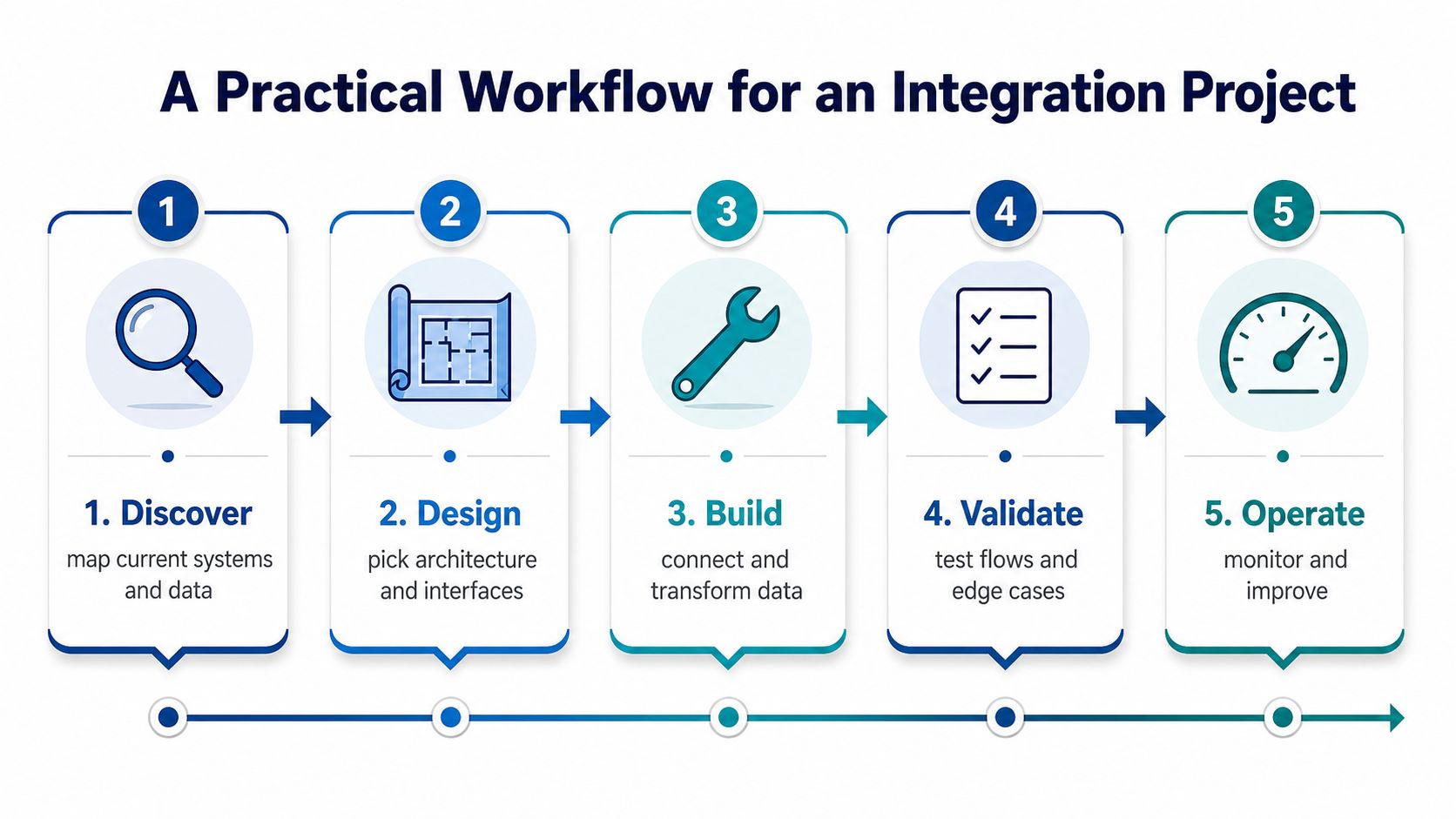
A Practical Workflow for an Integration Project
A machine can run well on its own and still fail as a system if the handoffs are weak. A hydraulic integration project should start with the business outcome, whether that is less downtime, faster commissioning, better traceability, or clearer fault-finding. Those outcomes need to be written down before anyone selects a PLC, valve, gateway, or software platform.
Start with the current state
Begin by mapping the existing machine, control panels, data flows, and manual workarounds. Which signals are already digital, which are still hard-wired, and which are being retyped by staff into another system? That inventory shows where friction sits and where integration will change day-to-day work.
The aim is to see the whole path, from a pressure switch or temperature sensor through to the maintenance record. If the same fault is logged in one place, ignored in another, and entered differently by operators on shift, the project has exposed a process problem as much as a hardware one.
Define the interfaces before the build
Interface control documents matter because they remove guesswork. They should state signal types, data ownership, naming rules, alarm behaviour, and who is responsible for each handoff. If a valve block is expected to send fault information to a controller, and the controller is expected to forward that event to maintenance, the chain has to be written down before the build starts.
This is also the point to bring in application engineering support, especially when the hydraulic circuit, control logic, and plant systems all need to fit together. A clear interface spec is like a drawing with dimensions, it tells every supplier what they must match and where tolerance ends.
Build and validate in stages
Systems engineering treats integration as verification and validation, not just installation, as described in SEBoK system integration. Check the interfaces in stages, confirm the static and dynamic behaviour of each link, and prove the whole chain before release. In a hydraulic project, that can include bench tests for signal response, simulated alarms, and checks on how the PLC reacts when a sensor fails.
The practical test is simple. If a fault appears in the valve manifold, does the controller read it correctly, does the HMI present it in a usable form, and does the maintenance system receive the right event without manual re-entry? If any one of those steps breaks, the system is only partially integrated.
Hand over with ownership intact
The project is not finished when the machine turns on. Operators need clear screens, maintenance teams need access to alarms and service records, and the support route has to be documented. The more connected the system is, the more important it becomes to know who owns each data path and who gets called when it fails.
Good integration does not hide complexity. It makes ownership visible.
For commissioning and acceptance testing detail, the guide on testing and commissioning is the right place to look when a project reaches the prove-it stage.
Real-World Examples in Mobile and Industrial Applications
A mobile machine makes the idea easier to grasp because the environment is unforgiving. Take an agricultural or mobile unit with a reversible gear pump, proportional control valves, a machine controller, and a telematics platform. The pump and valves manage motion, the controller decides what happens next, and the telematics layer pulls status and diagnostics so faults can be seen off-site.
In that setup, integration is not cosmetic. It means the machine controller, the sensor set, and the telematics feed are aligned so a service engineer can trace a pressure issue without guessing which component failed first. Operators get better visibility, and maintenance staff spend less time on blind inspections.
A factory-floor example looks different, but the logic is the same. A bespoke power pack, CETOP valves, and a hydraulic clutch might feed a PLC that talks to SCADA, while production events move into MES and ERP. The machine side handles motion and sequencing, while the business systems receive state, output, and maintenance information in a form they can use.
That kind of architecture is where standards and disciplined interfaces matter. The PLC does not need to know every ERP process, and ERP does not need to understand every valve state, but the handoff between them has to be reliable. If it is, operators see fewer unexplained stops, and planners can trust the data that comes out of the line.
The pattern is the same in both cases. Integration turns a machine from a collection of parts into a system that can be run, diagnosed, and supported as a whole.
Common Pitfalls and Misconceptions
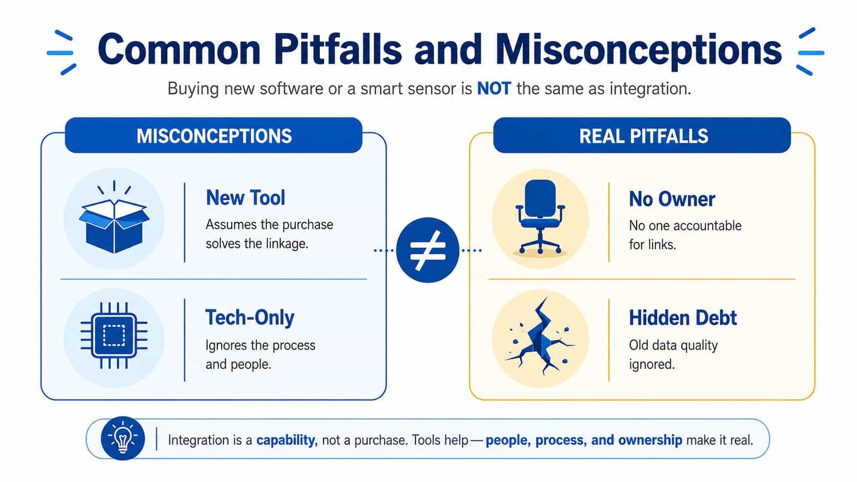
A control cabinet full of smart parts can still fail to act as a system. A pressure sensor may report accurately, a cloud dashboard may display the reading, and a PLC may accept commands, yet the project still needs a defined interface, a data model, a support owner, and a test plan before it behaves like one integrated hydraulic or industrial setup.
What goes wrong most often
One common failure shows up on hydraulic projects where a mobile OEM buys a smart valve block and assumes the work is nearly done. The valve can still need matching signal ranges, controller mapping, alarm handling, and maintenance documentation before it fits into the wider machine. A smart component may be technically sound, while the project around it remains poorly joined.
Interface mismatches are common, especially when one supplier expects analogue signals and another designs for digital messaging. Skipped interface control documents create trouble later because neither side has a clear record of what the other must supply. The hardware is usually not the problem, the gap between expectations is.
Cybersecurity is another weak point. The UK Government's Cyber Security Breaches Survey reported that 50% of businesses and 32% of charities had a cyber security breach or attack in the previous 12 months UK Cyber Security Breaches Survey 2024. For integrated hydraulic, maintenance, and monitoring systems, that makes centralised authentication, logging, and data-handling rules part of the engineering brief. The same logic applies to access to pumps, valves, controllers, and remote support tools.
Do not treat integration as a one-off purchase. It is an operating discipline that needs ownership over the full asset life.
Vendor lock-in can also creep in when proprietary protocols are chosen too early. The system may run properly, but support becomes harder if only one supplier can touch it. That matters in UK industrial environments where spares strategy, service access, and lifecycle support affect total cost of ownership.
Poor handover creates another problem. Downtime does not only happen during the first cut-over. Weak testing and unclear responsibility can bring the issue back every time the plant changes state, the controller updates, or a supplier replaces a component. For a practical acceptance mindset, testing and commissioning guidance is useful because integration only counts when the interfaces have been proved under realistic conditions.
Testing, Checklist and Recommendations for Buyers
A sensible buyer does not ask, “Does this component work?” They ask, “Can this component be integrated, tested, supported, and maintained inside my wider machine or plant?” That question changes what gets bought and who needs to be involved.
For a practical acceptance mindset, the article on testing and commissioning is useful because integration only counts when the interfaces have been proved under realistic conditions. Staged validation matters, especially where hydraulic behaviour, control logic, and data exchange all depend on one another.
Before you place an order, check these points:
- Interface specification: confirm signal types, data formats, and ownership of each handoff.
- Cybersecurity and access: decide who can log in, what gets logged, and how connected systems are protected.
- Documentation: make sure drawings, tag lists, alarm descriptions, and support notes are included.
- Spares and support: ask how the system will be maintained if a key component or software link fails.
- Vendor coordination: clarify which supplier owns the hydraulic build, which owns controls, and which owns software integration.
If the project needs a hydraulic specialist to select components as a system, MA Hydraulics Ltd can provide that sort of support alongside supply of power packs, valves, pumps, manifolds, and related assemblies. If the project also involves PLC logic, SCADA, or cloud software, then a controls or software partner needs to sit at the same table from the start.
The right result is a system that is easier to fault-find, cleaner to audit, and more supportable over its lifecycle.
MA Hydraulics Ltd helps UK engineers and buyers connect hydraulic components, power packs, valves, and monitoring hardware into practical machine systems. If you're planning an integration project and want to reduce the risk of mismatched interfaces or poor commissioning, visit MA Hydraulics Ltd or call 01724 279508 today, or send a message through the contact page to discuss your application.
