
The crate is open, the power pack is on the floor, and the parts list is clipped to the bench. This is the point where good installs separate themselves from expensive ones. A hydraulic system can look tidy at first fit and still fail on first pressure, or worse, fail later because somebody rushed the checks that nobody sees.
Most rework starts long before the first hose is tightened. It starts with one mismatched fitting, one contaminated port, one hose routed where it can rub, or one pressure test done too quickly to catch a slow leak. On a busy shop floor, that's exactly the stage people try to speed up.
Good installation guidelines aren't paperwork for the sake of it. They're what stop downtime, protect operators, and save you from tearing half the machine apart a week after handover.
Your Foundation for a Successful Installation
A first major install usually feels straightforward for the first hour. The unit arrives. The drawing looks clear. The mounting area seems ready. Then the awkward details appear. A port thread doesn't look quite right. The hose route that worked on paper fouls a guard on the physical machine. The valve stack leaves less spanner access than expected. That's where field judgement matters.
The technicians who stay out of trouble don't rely on assumption. They build from verification. Before a component goes on the frame, they check what it is, how it seals, how it will be serviced, and what failure would look like if they get it wrong. That habit matters just as much on a small power pack as it does on a larger industrial build.
For firms managing workflow across mechanical installation trades, there's a useful wider view in Bidwell's installation services sector, especially if you're thinking about how quoting, coordination and execution affect work before spanners even come out. On the hydraulic side, the same rule applies. A clean, verified start is what keeps the rest of the job under control.
If the job begins with a new hydraulic power unit, treat the assembly area like part of the system. Dirt on the bench becomes dirt in the oil. Missing tags become missing traceability. Loose planning becomes a fault report later.
Practical rule: If you can't explain why each component is there, how it seals, and how you'll test it, the install isn't ready to start.
Pre-Installation Checks and Component Verification
A hydraulic install usually goes wrong before the first hose is tightened. The trouble starts on the bench. A mixed box of adaptors, one damaged port, one wrong seal, and a unit that looked fine on the delivery note can turn into a leak chase, a stripped manifold, or a return visit after handover.
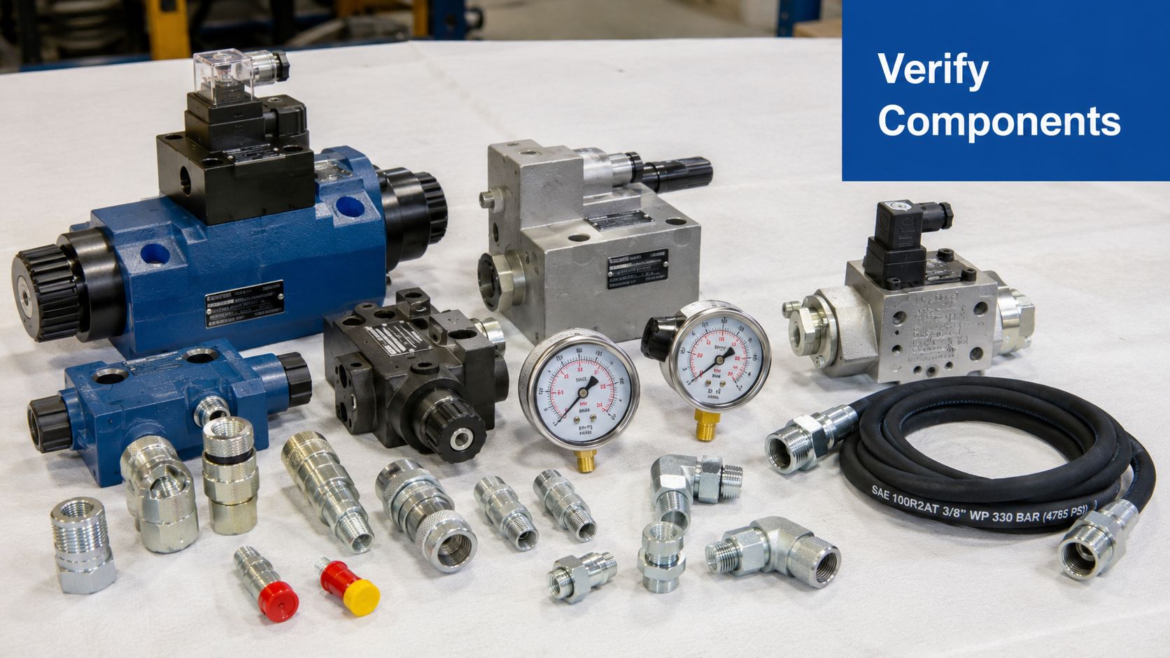
Verify every part against the job, not the box label
Set out the components against the schematic, bill of materials, and any customer-approved revisions. Do not trust packaging alone. I have seen correctly labelled cartons holding the wrong pressure switch, a metric adaptor in a BSP kit, and a replacement valve with the right coil but the wrong spool.
Check each item for four things before installation:
- Correct specification. Match the actual part number, pressure rating, flow range, voltage, port size, and seal type to the drawing and duty.
- Condition. Inspect threads, sealing faces, shafts, coils, connectors, castings, and mounting feet for transit damage or poor storage.
- Cleanliness. Port plugs and caps should be in place. Open ports, swarf, damp packaging, or dirty threads are warning signs.
- Serviceability. Confirm you can still reach bleed points, gauges, adjustment screws, and future replacement parts once the unit is built.
That last point gets missed far too often in the field. A component can be technically correct and still be wrong for the install if you cannot torque it properly, read it safely, or remove it without stripping half the machine.
If a thread form or sealing method is in doubt, identify it before anything is offered up. In UK work, confusion between BSPP, BSPT, metric, and NPT still causes expensive rework. A quick check with thread gauges, calipers, and a visual comparison against common hydraulic fitting types and thread forms is time well spent.
Use STAMP before any fitting reaches the manifold
STAMP is a sound bench check because it forces the right questions early: Size, Thread, Assembly, Material, Pressure. It is not paperwork for its own sake. It is how you stop a fitting that "looks about right" from becoming a leak path under test pressure.
| Check | What to confirm on the bench | Likely result if you skip it |
|---|---|---|
| Size | Hose bore, fitting size, port size, seat geometry | Flow restriction, pressure loss, excess heat |
| Thread | BSPP, BSPT, metric, NPT, and the actual sealing method | Cross-threading, false tightness, persistent leaks |
| Assembly | Correct nut, ferrule, insert, bonded seal, O-ring, or cone seat | Distorted joints, damaged threads, incomplete sealing |
| Material | Compatibility with fluid, environment, and adjacent metals | Corrosion, seal attack, shortened service life |
| Pressure | Continuous and peak rating above system demand | Deformation, cracked fittings, burst risk |
Pressure rating needs careful judgement. Bench figures and catalogue ratings are only part of the picture. Shock loads, cold starts, pressure spikes from valve shift, and trapped pressure in dead legs can all push a marginal fitting past its safe limit.
Read the small signs before they become faults
Missing port caps matter. Scratches across an O-ring face matter. Rust staining around a shaft seal matters. None of these faults improve once oil is in the system.
Do not try to pull damaged sealing faces together with torque. That usually ends with a leak at commissioning and a debate about whether the fault is the fitting, the seal, or the person on the spanner. Replace suspect parts while they are loose on the bench. It is cheaper, faster, and safer.
Serial numbers, pressure settings on supplied relief valves, and any component orientation marks should be recorded at this stage. Once the assembly is piped, wired, and tucked into a machine frame, traceability becomes slower and mistakes are easier to make.
A fitting that goes in smoothly is not proof that it is the right fitting. It only proves the threads engaged.
For junior technicians, this is the habit to build early. Verify first. Fit second. That discipline prevents the sort of field failures that waste a day on site and a week in paperwork.
Mechanical Mounting and Hose Routing
A new pack can run cleanly in the workshop, then come back a month later with a cracked clamp rail, weeping fittings, and a hose cover worn through to the braid. The usual cause is not a bad component. It is movement that was designed into the installation by accident.
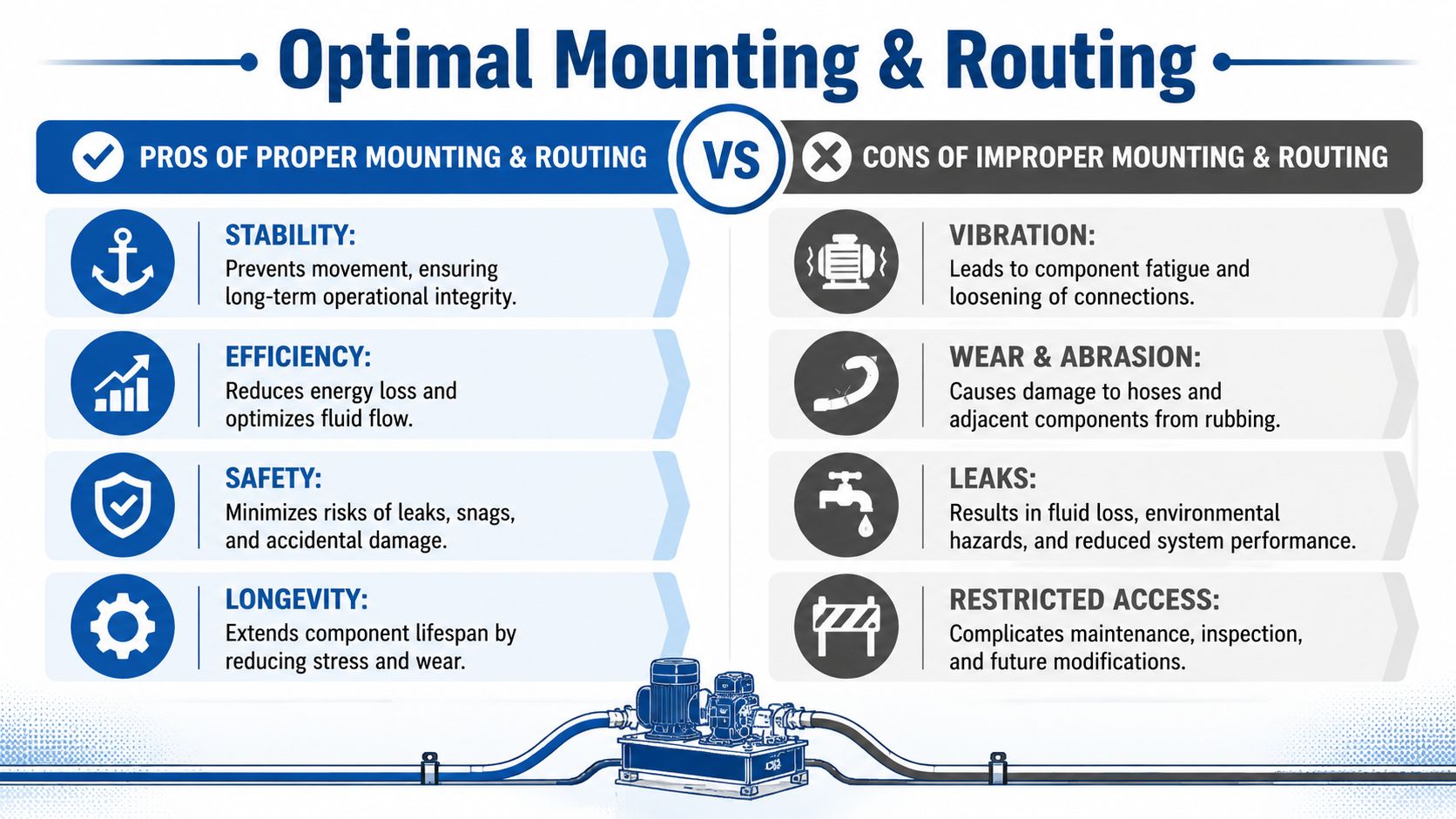
Mount the unit so the structure carries the load
Start with the frame, not the fasteners. The mounting surface needs to stay flat under operating load, with enough stiffness that the power unit is not being used to brace a weak skid or machine base. If the structure deflects, the pipework and hose ends see that movement first, and they usually fail before the frame does.
Bellhousing and coupling assemblies need the same discipline. If bolts are used to drag a motor and pump into line, the misalignment stays in the machine and shows up later as bearing noise, coupling wear, heat, and repeat seal issues. Set the faces square, confirm the feet are sitting naturally, and correct packing or frame errors before final tightening.
I tell junior fitters to watch for one simple sign. If a bracket only fits when you pry it into place, the bracket is wrong or the assembly position is wrong.
Route hoses for service conditions, not for the static machine
A tidy route on a stationary machine proves very little. The hose has to survive pressure pulsation, vibration, temperature change, cylinder travel, steering lock, guard removal, and a fitter leaning in later to change a filter. Field failures are often mechanical long before they become hydraulic.
Good routing usually means accepting that the shortest path is not the best one. A slightly longer run can give a larger bend radius, cleaner support points, better protection from abrasion, and enough slack for movement without putting side load into the fitting.
Check these points before you commit to clamps and final positions:
- Keep the hose in its natural bend. Do not force a tight turn straight out of the fitting.
- Remove twist. The layline should stay straight after installation.
- Keep clear of edges, covers, exhaust heat, and any surface that can rub through the outer cover.
- Stroke cylinders and articulate the machine fully. Check the route at every extreme, not just at mid-position.
- Support long runs where vibration will work at the joint or at a bend point.
- Leave access for future servicing so a routine filter change does not turn into hose damage.
For securing tube and hose runs cleanly, a properly selected clamp for tubing helps control vibration and prevents the slow wear that starts with movement you can barely see.
What experienced fitters check before sign-off
Watch the machine move. Do not just look at the installed route and assume it is fine.
Cycle every moving function through full travel and stand where you can see the hose body, not only the cylinder or actuator. Look for a hose that tightens at one end of stroke, a loop that drops onto a guard, or a bend that sharpens as pressure comes on. Those are the faults that create rework after commissioning.
There is also a maintenance trade-off to make. Routing that looks clean on day one can be a poor installation if it blocks access to filters, test points, drain plugs, or valve adjustments. In UK site work, where downtime windows are short and machines are often serviced in awkward conditions, that access matters. A route that gives up a little visual neatness but allows safe inspection and replacement is usually the better engineering choice.
Making Hydraulic and Electrical Connections
A lot of rework starts here. The pipework is mounted, the hoses look tidy, and someone wants to get the job finished. Then a fitting gets forced because it is “close enough”, a hose is pulled into line by the spanner, or the motor is bumped before isolation and phasing checks are complete. That is how a clean install turns into leaks, damaged ports, and an avoidable call-back.
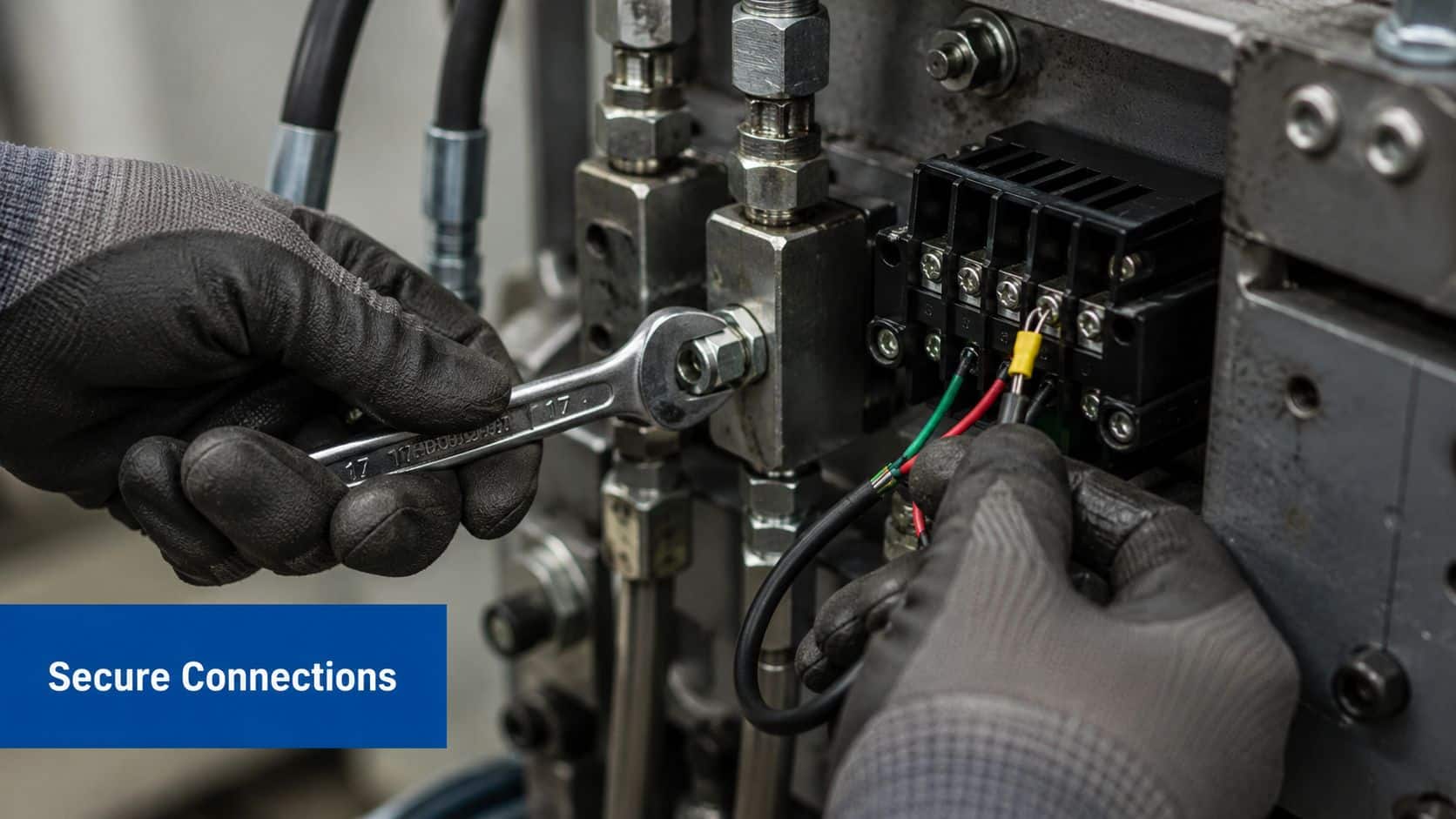
Hydraulic connections need identification before force
Start by identifying exactly what is in front of you. Do not rely on eye alone, especially on mixed-origin equipment common in UK workshops and site retrofits, where metric, BSP, and older replacement parts can all appear on the same machine.
A fitting that screws in a few turns proves very little. The seal may still be wrong, the thread form may be wrong, and the damage may only show when pressure and heat cycling start. British thread forms differ from metric. Whitworth-form hydraulic threads use a 55° thread angle, and that difference matters when you are checking compatibility and avoiding cross-threading or false sealing, as explained in this breakdown of British hydraulic fitting differences.
In practice, the check is simple. Measure the thread. Confirm the pitch. Inspect the sealing face. Then match the jointing method to the actual fitting standard, not to what someone thinks was fitted last time.
That discipline saves ports.
Tighten to specification, not feel
Torque is not a matter of experience or hand strength. It is a control measure. If the manufacturer gives a torque figure, use it with a calibrated tool and record it where your installation paperwork requires it.
Over-tightening distorts seats, crushes seals, and can leave the joint apparently sound until the first pressure spike. Under-tightening gives you the slower failure. Oil film around the fitting, dirt sticking to the damp patch, then a leak that only shows up once the machine is hot. Neither fault is acceptable on a new install.
A practical assembly sequence looks like this:
- Clean the joint first: Wipe ports, fittings, and sealing faces. Any grit left in the connection is now inside the system.
- Start every thread by hand: If it does not run freely, stop and recheck the thread and alignment.
- Confirm the sealing method: Bonded seal, cone seat, compression fitting, taper thread, or port seal all assemble differently.
- Let the hose sit naturally: Do not use the fitting to drag a hose into position or remove twist.
- Finish with calibrated torque: Tighten to the stated specification, then recheck orientation if the connection is adjustable.
Keep adaptors to a minimum as well. Every added joint creates another leak path, another tolerance stack, and another point where vibration can work on the connection. On packaged units and skid installations, this is a common field mistake. The drawing may allow it, but the machine pays for it later in maintenance time and oil loss.
Electrical work has to be controlled
Hydraulic faults and electrical faults often get mixed together during installation, so the electrical side needs the same discipline. Treat the system as live until it is isolated, locked off, and proven dead.
The order matters:
- Isolate and lock off: Prevent anyone else from restoring power while work is in progress.
- Prove dead correctly: Check with suitable test equipment before touching terminals or opening further components.
- Verify supply details: Confirm voltage, phase, and control arrangement against the motor and starter data.
- Check earth bonding: Chassis, motor frame, and associated metalwork must be properly earthed.
- Confirm rotation safely: Only bump-test motor direction when the hydraulic side is ready for that check and the risks are controlled.
Reverse rotation can damage a pump very quickly. I have seen new units ruined because someone wanted a quick direction check before confirming the basics. Five extra minutes on isolation, phasing, and terminal checks is cheaper than one replacement pump.
For compact packaged units, MA Hydraulics Ltd supplies components and assembled power solutions that still need the same care on site. Factory assembly reduces some variables, but it does not remove the installer's responsibility for correct connection, isolation, and verification.
Electrical faults often get blamed on controls first. Start with supply, phasing, earthing, termination quality, and safe isolation. That is usually where the real fault is found.
Safe Commissioning and Compliance Testing
At this stage, the unit is bolted down, piped up, and wired. This is the point where expensive mistakes show themselves. A rushed first start can score a valve block, damage a pump, or leave you chasing a leak that should have been found before the machine ever saw load.
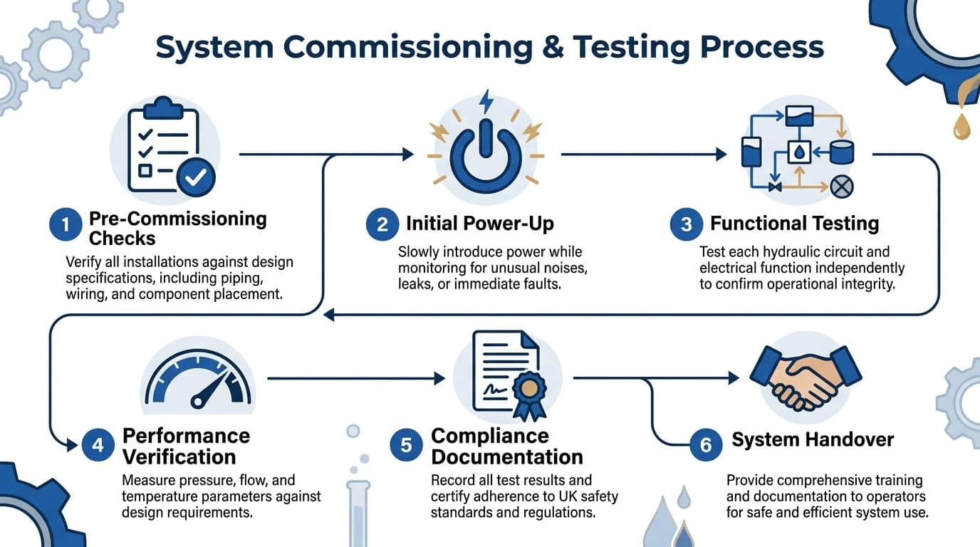
Commissioning is a controlled proof process. In UK practice, BS EN ISO 4413 sets the baseline for safe hydraulic system testing and verification, including the expectation that pressure risks are addressed through correct component selection, controlled testing, and proper records, as outlined in this explanation of BS EN ISO 4413 fluid power safety standards. The field reality is simple. If you cannot prove the system is safe and tight under test conditions, it is not ready for service.
Fill and vent with care
Start with the oil. Use the specified fluid, confirm cleanliness, and fill the reservoir in a way that does not introduce dirt or water. I have seen new installations contaminated before first start because someone left a filler cap open during other site work.
Then vent the circuit properly. Air trapped in high points, cylinder caps, or suction lines will distort everything you are trying to assess. The pump sounds rough, actuators move in jumps, and pressure readings drift enough to send you looking in the wrong place.
Bring the system into low-pressure circulation first. Give the oil time to displace air and stabilise. Watch the tank for foaming, listen for pump noise changes, and inspect every joint you can safely see. Do not apply full load just because the motor is running and something is moving.
A useful visual overview sits below.
Pressure testing has to be staged
Good commissioning is deliberate. Raise pressure in steps, hold at each stage, and inspect before going further. That approach catches the faults that cost time later, such as a fitting that only starts to weep once the pipe warms slightly, or a hose that twists under pressure because it was installed with preload.
Use a sequence like this:
| Stage | What you do | What you’re checking |
|---|---|---|
| Initial check | Low-pressure circulation | Flow path, pump sound, obvious leaks |
| Intermediate rise | Increase pressure in steps | Joint integrity, hose behaviour, gauge response |
| Hold periods | Pause at each stage | Pressure decay, seepage, slow leaks |
| Full operational pressure | Reach test condition | System integrity at duty pressure |
| Functional checks | Operate valves and actuators | Correct sequence, stable response, smooth motion |
Do not accept a damp fitting, a sweating manifold face, or a hose end with a trace of oil. On a new installation, that is a failed result. In the workshop, small leaks become breakdowns. On site, they become downtime, slip hazards, and call-backs.
There is also a judgement call here. Some machines can be function-tested safely with minimal load during early pressure stages. Others should stay unloaded until you are satisfied the circuit is fully vented and holding pressure cleanly. Choose the lower-risk route. The extra half hour is usually cheaper than replacing a damaged component.
Compliance is what you can prove
A machine that runs is not automatically a commissioned machine. The test record has to match the build on the floor. Record the pressures reached, the hold periods, the gauges used, and the identification of the main components fitted. If a relief valve was reset, note the final setting. If a hose was changed during test, update the record there and then, not at the end of the week when details get lost.
A passed test only counts if someone else can read the record and see exactly what was checked.
Site discipline separates a clean handover from rework. In UK installations, especially where insurers, principal contractors, or end users expect traceability, poor paperwork creates the same trouble as poor pipework. If a fault appears later, the commissioning sheet is often the first thing people ask for.
Operator and maintenance briefing also belongs here, but keep it tied to the tested machine. Show isolation points, normal operating pressures, warm-up expectations, and what signs mean the unit should be stopped and inspected. Generic handover talk is not enough. The people taking over need information that matches the system you have just proved safe.
Final Checks and Maintenance Handover
A system can pass its pressure test in the afternoon and still come back as a breakdown on Monday morning if the final checks are rushed. The faults at this stage are usually small, practical ones. A loose locknut on a relief valve, a hose clip missed on a return line, an unreadable tag on an isolation point, or a maintenance team left guessing which filter element was fitted.
Run the machine long enough to see stable behaviour, not just movement. Listen to the pump once the oil has some heat in it. Watch for drift, hunting, pressure creep, and fittings that stay dry at first but begin to sweat as the circuit reaches working temperature. Check that guards, clamps, labels, and access covers are back in place before handover. Many call-backs start with something simple that was removed during test and never refitted properly.
The handover standard is straightforward. The machine on the floor, the drawings in the pack, and the settings recorded on the sheet must match. If they do not, the next technician loses time tracing a system that exists only on paper.
A useful handover pack should include:
- Final schematic: The marked-up version that matches the installed pipework, hose routing, valve positions, and any approved site changes.
- Component schedule: Include model references and serial numbers where they matter for service, warranty, or traceability.
- Test and settings record: Record final operating pressures, relief settings, switch points, and any adjustments made during commissioning.
- Deviation log: Note what changed from the original design, who approved it, and why it was changed.
- Maintenance information: Show filter locations, service intervals, fluid specification, greasing points where applicable, and safe isolation points.
I also want the operator and the maintenance fitter to see the machine run in its handed-over condition. Show them the normal start-up sequence, warm-up expectations, and the sounds and symptoms that mean stop the unit and investigate. In UK sites, that short briefing often prevents the first avoidable failure, especially where shift teams inherit equipment without speaking to the installer.
Good installation work shows up months later. It shows up when a hose can be replaced without stripping half the machine, when the right filter is ordered first time, and when a pressure setting can be verified from the record instead of guessed on site.
If you need help with component matching, replacement parts, or a complete hydraulic build, speak to MA Hydraulics Ltd. Phone 01724 279508 today, or send us a message.
