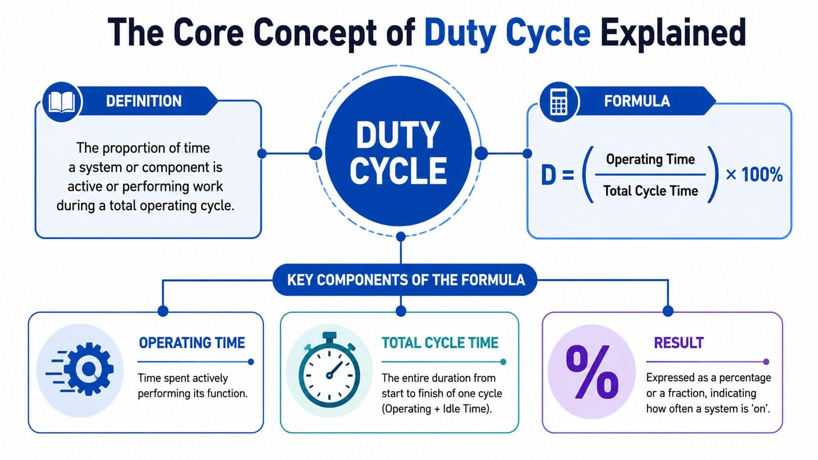
Duty cycle is the percentage of time a component is active within a full operating cycle, calculated as D = (Operating Time / Total Cycle Time) × 100%. If a device runs for 10 seconds on and 10 seconds off, its duty cycle is 50%.
If you're checking a spec sheet, trying to stop a solenoid coil from running too hot, or wondering why a power pack keeps cooking the oil on a machine that “doesn't run all day”, duty cycle is usually the missing piece. In hydraulic systems, it isn't just a tidy calculation for the drawing office. It affects motor temperature, fluid life, contamination rates, component choice, reservoir sizing and, in the worst cases, whether a machine survives or keeps returning with the same expensive fault.
A lot of people first ask what is duty cycle when they're looking at an intermittent machine. A tipper, press, clamp, tail lift or valve bank may only work in short bursts, so the assumption is that the system is under light stress. That's often wrong. Short bursts at high load can be harder on a hydraulic system than many expect, especially when cooling, rest periods and actual operating patterns don't match the original design assumptions.
The Core Concept of Duty Cycle Explained
A hydraulic power pack can look lightly used on paper and still fail early in service. We see it on tippers, presses and compact bespoke units where the motor only runs in short bursts, yet the oil darkens early, filters load up faster than expected, and coil or motor temperatures keep creeping up. In practice, duty cycle is the measure that explains that gap between assumed use and actual stress.
At its simplest, duty cycle tells you how long a component is active during a full repeating cycle of operation and rest. The standard formula is D = (Operating Time / Total Cycle Time) × 100%, as outlined in this duty cycle explanation for electric ball valves.
Intermittent and continuous duty in real machines
A short-cycle hydraulic unit works more like a sprinter than a steady-running process line. It can handle high demand for limited periods, but only if the off-time is long enough for the motor, coil, pump body and fluid to lose heat. A continuous-duty unit is designed for a very different job. It is built to carry load for extended periods without depending on recovery time to stay within temperature limits.
That distinction matters because hydraulic components do not suffer evenly. A motor may survive repeated starts, while the oil bears the brunt of the punishment. Once fluid temperature runs high for too long, oxidation accelerates, varnish forms more readily, and contamination control becomes harder because degraded oil carries and deposits more by-products through the system. In UK service work, that often shows up first as sticky valves, shortened filter life and complaints that the machine has become erratic after a period of apparently normal use.
What the percentage actually means
The percentage itself is simple:
- 50% duty cycle means the component is active for half of the total cycle time.
- 25% duty cycle means it operates for one quarter of the cycle and rests for the remaining three quarters.
- 100% duty cycle means continuous operation with no rest period.
A device that runs for 10 seconds on and 10 seconds off has a 50% duty cycle.
The costly mistake is assuming the percentage alone tells the whole story. It does not. A pump running at 50% duty on low pressure is a different thermal problem from a pump running at 50% duty near relief pressure. The time fraction may match, but the heat generated, the stress on seals, and the rate at which the oil condition deteriorates do not.
Practical rule: Duty cycle is a temperature and contamination question as much as a timing question. If the component cannot reject heat during the rest period, the system pays for it in fluid life, filter loading and avoidable downtime.
Why the definition matters in hydraulics
In hydraulic design, duty cycle sets the baseline for choosing the right motor rating, reservoir size, cooling method and valve arrangement. Get it right, and a compact power pack can do years of service without cooking the oil. Get it wrong, and the machine may still pass a factory test but return later with overheated fluid, premature seal wear, sludge in the tank and a maintenance bill that should have been designed out at the start.
That is why experienced engineers do not treat duty cycle as a box-ticking figure from a catalogue. It is one of the first checks used to judge whether a system is indeed matched to the way operators will use it on site, cycle after cycle, day after day.
Calculating Duty Cycle for Hydraulic Components
Most duty cycle mistakes happen because the calculation is easy, but the actual operating pattern isn't written down. The fix is simple. Measure the active time, measure the full cycle, then do the arithmetic properly.
Example one for a hydraulic pump on a tipper trailer
Take a tipper trailer pump that runs for 45 seconds to complete its lift function, then rests for 75 seconds before the next cycle.
The formula is:
Duty cycle = Operating time / Total cycle time × 100%
So:
- Operating time = 45 seconds
- Total cycle time = 45 + 75 = 120 seconds
Calculation:
- 45 / 120 × 100 = 37.5%
That means the pump is operating for 37.5% of the full cycle and resting for the remaining portion.
This sort of worked check matters because many people only think about the lift time. They forget the total cycle includes the waiting period between operations. If you only log the “on” period and ignore the complete cycle, you'll overestimate the severity in some cases and underestimate it in others, especially where operators bunch cycles together.
Example two for an industrial solenoid valve
Now take a valve on an automated press. The solenoid is energised for 2 seconds and de-energised for 3 seconds.
So:
- Operating time = 2 seconds
- Total cycle time = 2 + 3 = 5 seconds
Calculation:
- 2 / 5 × 100 = 40%
That gives a 40% duty cycle.
In a factory, this type of cycle can repeat continuously through a shift. The arithmetic is still easy, but the consequences are different. A fast-cycling solenoid may only be on for short periods, yet if those short periods keep repeating with limited cooling, thermal stress can still become the limiting factor.
A simple method on the shop floor
If you need to calculate duty cycle on live equipment, use this process:
-
Record the active time
Measure how long the pump, motor, valve or actuator is working. -
Record the idle or rest time
Include the full period where the component is not working but remains part of the cycle. -
Add them together
That gives the total cycle time. -
Apply the formula
Divide active time by total cycle time and multiply by 100.
A manual stopwatch is often enough for slower machinery. For repetitive automated equipment, a data logger or control signal trace gives a much cleaner picture.
If the machine sees different operating patterns through the day, calculate duty cycle for the heaviest realistic pattern, not the easiest one. Systems fail in peak use, not in quiet periods.
What people usually get wrong
The common errors are familiar:
- Ignoring clustered operation. A machine may be idle for long periods, then run repeatedly in a short window.
- Using theoretical times. The PLC sequence may say one thing, but the machine in production often does another.
- Forgetting load effects. Two components can share the same duty cycle on paper but run at very different thermal stress levels depending on pressure and resistance.
The number itself is only the start. The useful part is what it tells you about heat, cooling demand and expected service life.
Thermal and Performance Implications
Duty cycle matters because heat is what usually ends the argument. When a component operates, not all input energy becomes useful motion or hydraulic work. Some of it becomes heat in the motor, coil, fluid and surrounding hardware. If the rest period is too short, that heat stays in the system.
In electro-hydraulic controls, the relationship is explicit. In digital hydraulic valve systems, duty cycle is defined as %DC = (tON / τ) × 100, and that ratio directly affects thermal management and solenoid longevity, as noted in this research on digital hydraulic valve systems.
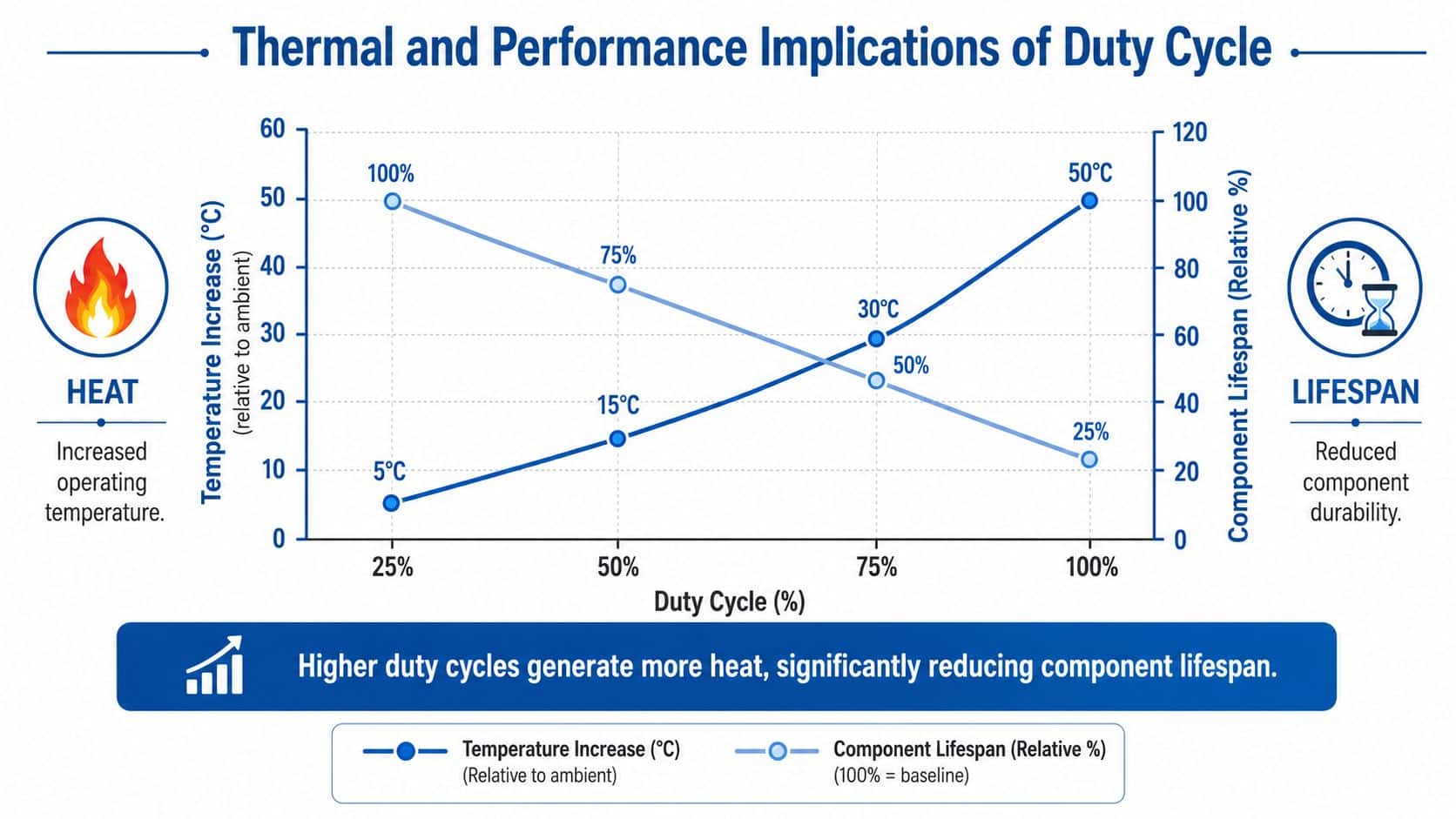
What higher duty cycle does to a system
Once duty cycle rises, several things start happening at once:
- Coils run hotter because they stay energised for longer.
- Fluid temperature climbs because the system has less time to reject heat.
- Seals and hoses age faster when exposed to higher operating temperatures.
- Performance drifts as oil viscosity changes and internal leakage behaviour shifts.
This is why a machine can appear acceptable when cold and become erratic later in the day. The problem isn't always a failed part. Sometimes the system is being asked to work beyond the cooling margin built into it.
Hydraulic heat is often a design issue, not a maintenance issue
A lot of overheating complaints get pushed into maintenance, but the root cause is often sizing. If the power unit, reservoir or cooling arrangement doesn't match the actual operating duty, the machine is carrying a thermal penalty from day one.
That's also why external cooling knowledge can be useful beyond pure hydraulics. Anyone comparing heat rejection approaches may find expert advice for transmission cooling system replacement helpful because the same engineering logic applies. Heat has to go somewhere, and if the cooling path is weak, the component pays.
For a closer look at controlling heat in hydraulic equipment, thermal management in hydraulic systems is worth reviewing.
A component that survives at a moderate duty cycle can fail early at a higher one without any change in pressure setting, simply because the cooling window disappears.
Why “it only runs for a short time” can be misleading
Short operating bursts don't guarantee safety. Repeated bursts can create a ratcheting thermal effect where temperature rises a bit each cycle and never fully returns to baseline.
That's particularly true with compact hydraulic packs, enclosed installations and valve manifolds mounted where airflow is poor. In those situations, the machine may never get the rest it needs, even if the operator believes it's intermittent.
If you want reliability, treat duty cycle as a thermal design input, not a box-ticking calculation.
Sizing Power Packs and Components with Duty Cycle
A common failure pattern in bespoke power packs starts at the quotation stage. The flow, pressure and motor size look right, the machine goes into service, and six months later the site is dealing with hot oil, varnish, blocked return filters and unplanned stops. In many cases, the primary error was duty cycle. The pack was sized for a cleaner operating pattern than the machine experiences.
For hydraulic power pack sizing in UK industrial and agricultural work, duty cycle needs to sit alongside actuator speed, peak load and ambient conditions from the start. A low-duty application can often run well with a straightforward fixed-displacement arrangement and reservoir cooling alone. High-duty applications usually need more thermal margin, better control of unloaded flow and a motor that can carry its actual on-time without running beyond its rating. A 15% duty cycle mismatch in 11 kW power packs has been linked to £2,400 per year in extra energy costs and 18 hours per year of downtime in UK factories, according to Hydrastore's lifecycle cost analysis.
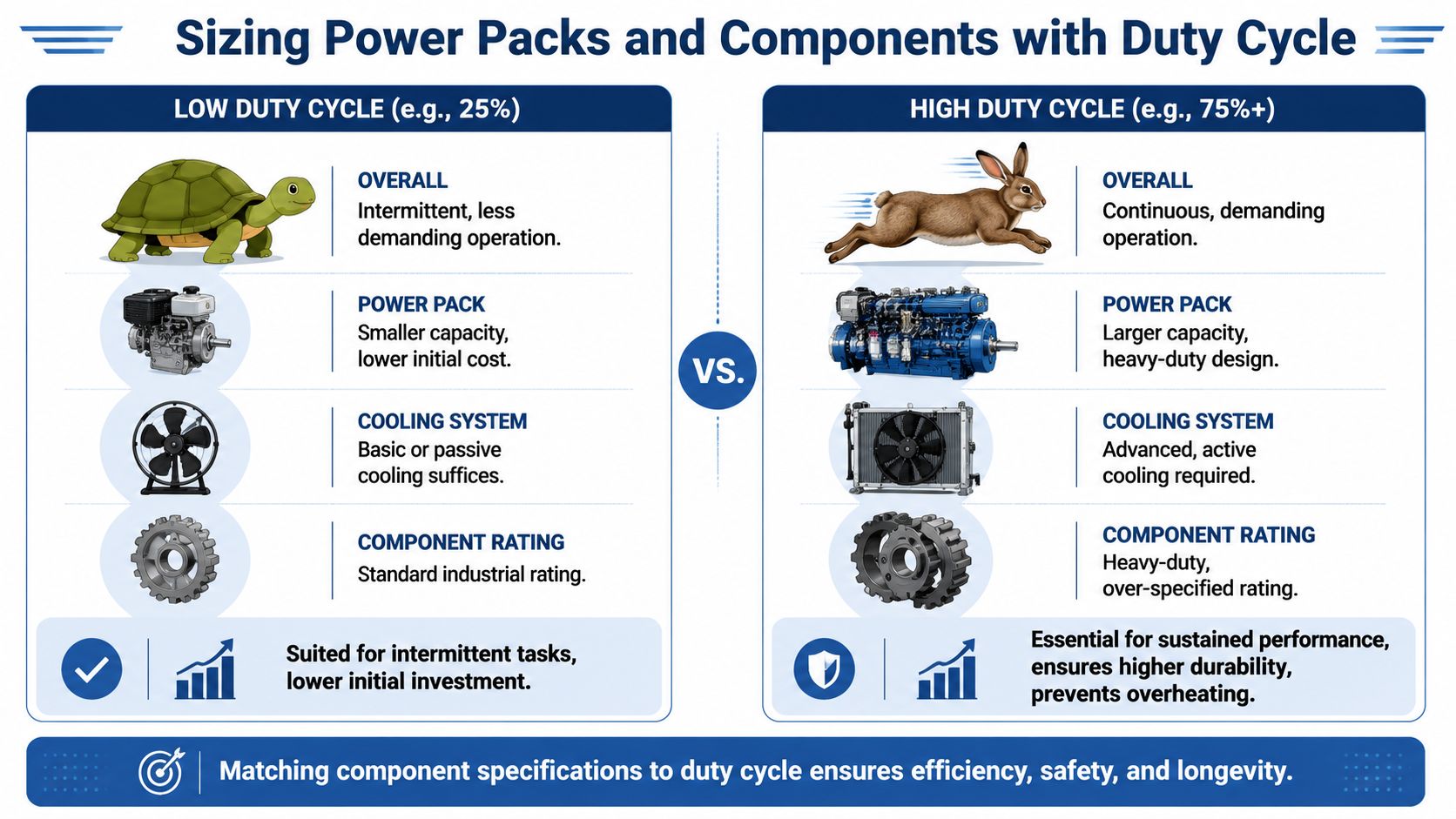
Low-duty and high-duty applications need different sizing margins
Intermittent machinery gives you more room to keep the design simple. If the run periods are short and the pauses are long enough for temperature to settle, a compact pack with sensible reservoir volume and standard component ratings can be perfectly serviceable.
Repeated cycles with limited rest are a different engineering problem. I size these systems with much closer attention to heat rejection, contamination control and fluid residence time, because the penalties show up quickly in the oil as well as the hardware. Once oil spends more time hot, oxidation accelerates, deposits build faster and filters pick up the by-products. That is where a cheap power pack becomes an expensive one.
The design changes usually affect four areas:
- Motor selection to match actual on-time, not assumed intermittent use
- Reservoir volume to give the oil enough dwell time for deaeration and heat release
- Circuit strategy to avoid dumping excess flow across relief valves during long active periods
- Cooling and filtration to control temperature and contamination as duty rises
For motor selection, guidance on how to size a hydraulic motor is a useful reference point when matching load, speed and operating pattern.
Where cost shows up in the real machine
Undersizing rarely announces itself on day one.
It usually appears as a chain of smaller losses. The motor runs hotter than expected. Oil change intervals shorten. Filter elements load up sooner because hotter fluid carries more oxidation products and loosened deposits through the system. Seals harden earlier. Operators start reporting slow cycles late in the shift. Maintenance teams then spend money treating symptoms rather than correcting the original sizing error.
That matters in the UK because energy cost, labour cost and downtime cost all hit at once. On a bespoke pack, a modest increase in up-front spend for correct reservoir capacity, unloading logic or oil cooling is often cheaper than repeated callouts and fluid replacement over the first year of service.
A useful comparison exists outside hydraulics too. Anyone weighing intermittent versus sustained electrical load can see the same rating problem in this guide for DIYers and contractors. The principle is the same. Short bursts on a spec sheet do not describe continuous real-world use.
| Application pattern | Typical sizing decision | Likely long-term outcome |
|---|---|---|
| Intermittent operation with genuine cooling periods | Standard pack layout, basic reservoir cooling, moderate thermal margin | Stable temperatures, acceptable oil life, predictable service intervals |
| Repeated or sustained operation with little rest | Higher-rated motor, more dwell volume, reduced unloading losses, added cooling and tighter filtration control | Lower downtime risk, cleaner fluid, better component life and lower operating cost |
What works in practice
Start with the machine cycle, not the catalogue.
Record how long the pack is under load, how often peak demand repeats, and how the duty changes across a full shift. Then size the pack for that real pattern with a margin for seasonal ambient temperature, fouled coolers and operator behaviour. On bespoke units, good engineering proves its worth.
The question is simple. Can the power pack carry the actual duty cycle without driving oil temperature and contamination generation to a level the maintenance plan cannot contain?
If the answer is uncertain, the pack is not sized properly.
Interpreting and Testing Duty Cycle Ratings
A machine can pass commissioning on Monday and be cooking its oil by Friday if the duty rating has been read too loosely. I see this most often on bespoke power packs where the catalogue rating looked acceptable, but the installed machine spends far longer under load than anyone allowed for. The cost shows up in overheated fluid, faster varnish and particulate formation, and service intervals that arrive far earlier than the owner budgeted.
Pressure matters, but pressure alone does not tell you whether the duty claim is realistic. In UK industrial work, many hydraulic circuits operate in the 200 to 400 bar range depending on actuator sizing and operating pattern. Lifecycle control depends just as much on fluid checks at sensible intervals and on oil analysis, as outlined in this guide to how hydraulics work.
Reading the rating properly
Duty cycle ratings need to be read in the context of the whole installation, not as a standalone line on a datasheet.
Separate the rating into three parts:
- Electrical duty for coils, motors, relays and contactors
- Mechanical duty for shafts, bearings, gears and moving valve elements
- Thermal duty based on how the assembled machine sheds heat
That third point catches people out. A solenoid coil may be within its electrical limit and still fail early because it sits above a hot manifold inside a poorly ventilated enclosure. A pump and motor set may also look comfortable at nominal power, then spend a full shift close to relief pressure because the actual machine cycle bears little resemblance to the test condition used for the original rating.
How to test actual duty cycle
On site, start with evidence, not assumptions.
A basic timed study is often enough to expose a mismatch. Record:
- Active time when the component is energised or delivering flow
- Idle time when it is de-energised or unloaded
- Cycle frequency across a representative production period
- Peak events such as repeated clamping, stalled movement, or long holds at pressure
On automated equipment, pull the signal from the PLC, relay output, or motor starter and log it properly. That removes operator memory from the process and gives a record you can compare against oil temperature, motor case temperature, and alarm history. Pairing runtime data with temperature monitoring for hydraulic systems usually shows whether the published duty rating matches the thermal reality of the installation.
If the logged on-time looks acceptable but oil temperature keeps climbing, treat temperature as the stronger warning sign.
What a realistic test should prove
A useful duty cycle test does more than confirm whether a component survives a short run. It should show four things. First, whether the component stays within its temperature limit at normal ambient conditions. Second, whether it still has margin when filters load up, coolers foul, or operators extend the cycle. Third, whether fluid cleanliness begins to deteriorate as heat rises. Fourth, whether the ownership cost still makes sense once shortened oil life and extra maintenance are priced in.
That last point is usually missed. A pack that runs marginally hot may not fail immediately, but it can still become expensive. In practice, every unnecessary rise in operating temperature pushes oxidation harder, shortens fluid life, and increases the contamination burden on filters and wear surfaces. On a bespoke UK power pack, that can turn a modest design shortcut into repeated callouts, more frequent oil changes, and avoidable downtime.
Field judgement still matters
Instrumentation helps, but experienced site checks still have value. Reservoirs that stay unusually hot after routine production, motor frames that keep climbing in temperature through the shift, and valve banks that become difficult to inspect safely by hand all point to a duty problem worth investigating.
The same principle applies outside hydraulics. A guide for DIYers and contractors makes the point clearly in another trade. Intermittent-duty equipment cannot be treated as continuous-duty equipment without paying for it later.
Best Practices for System Longevity
A hydraulic pack can look perfectly serviceable on day one, then spend the next 18 months burning through oil, filters, and callout time because the actual duty cycle was higher than the design assumption. I see that pattern more often on bespoke power packs than outright component defects. The expensive part is rarely the first failure. It is the steady increase in oil temperature, contamination load, and maintenance frequency that follows.
Fluid health deserves more attention than it usually gets in duty cycle discussions. Systems operating at more than 85% duty cycle have been linked to 30% faster particulate generation due to heat stress, while a 2025 UK Agricultural Machinery Reports reference indicates only 12% of farmers monitor fluid condition based on duty cycle metrics, according to this summary on hydraulic system fundamentals. In practical terms, that means a pack that is only slightly undersized or run too hard can start costing money long before anyone sees a major breakdown.
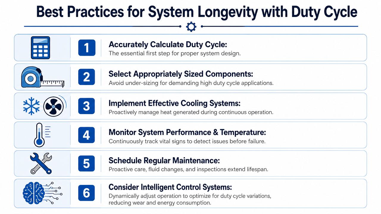
Six habits that prevent expensive trouble
-
Calculate first, don't assume
If on-time and off-time are not measured, the design basis is weak. On UK site work, small errors in cycle assumptions often show up later as hot running, nuisance trips, and shortened oil life. -
Size components for the actual working pattern
A pump, motor, or solenoid that survives a short acceptance test may still be wrong for repeated production duty. Intermittent use on paper can become near-continuous use once the machine is in service. -
Give the system a way to lose heat
Reservoir capacity, cooler performance, and actual dwell time all affect oil life. If duty cycle goes up but heat rejection does not, oxidation and varnish formation follow. -
Watch the oil, not just the hardware
Rising particle counts, faster filter loading, darkening oil, and a drop in fluid life often appear before hard parts fail. Those are operating-cost warnings, not housekeeping details. -
Check operating behaviour after installation
Operators rarely use a machine exactly as the original sequence chart suggests. A week of real production data is often more useful than a tidy design assumption made in the workshop. -
Use controls intelligently where the application allows
Unloading circuits, pressure switches, timed rest periods, and sensible standby logic can cut unnecessary run time. That reduces heat input and usually lowers contamination rates as well.
What works in practice
The systems that stay reliable for years are usually the ones with boring discipline behind them. Duty cycle is measured, oil temperature is trended, filter condition is reviewed, and fluid analysis is used before wear becomes expensive.
The systems that become costly usually follow a familiar path:
- a compact pack is chosen without enough thermal margin
- off-time is assumed rather than logged
- oil changes are done by calendar habit instead of actual operating stress
- filter replacement is treated as routine maintenance, not a sign that contamination generation may be climbing
On a bespoke power pack, that difference has a direct cost. Extra oil changes, more filter elements, shortened pump life, and repeated service visits add up quickly. In UK operating conditions, where many machines work in dirty yards, warm enclosures, or long seasonal shifts, misjudging duty cycle is not a theoretical design error. It is a maintenance budget problem.
Clean oil will not stay clean in an overheated, overworked system. High duty cycle increases thermal stress, and thermal stress accelerates contamination.
A sensible operating mindset
Duty cycle needs to stay part of maintenance decisions after commissioning. If oil runs hotter than expected, filters load sooner, response slows, or coils and motors begin failing repeatedly, check the actual working pattern before replacing parts again.
That approach prevents a common and costly mistake. Engineers and maintenance teams sometimes treat repeated failures as isolated component issues when the underlying cause is cumulative thermal loading from the duty cycle the machine is operating under.
Frequently Asked Questions about Duty Cycle
What happens if a component briefly exceeds its duty cycle rating
A brief overrun won't always cause immediate failure, but thermal stress is cumulative. If a coil, motor or compact power unit repeatedly works beyond its intended rest window, heat keeps building and service life drops.
Does UK ambient temperature affect effective duty cycle
Yes. A component running in a warm factory corner, inside an enclosure or on machinery working hard in summer has less cooling margin than the same part in a cooler setting. That means practical duty capability can be lower than the nominal rating suggests.
Is electrical duty cycle the same as mechanical duty cycle
Not always. A solenoid coil may have one thermal limit, while the hydraulic or mechanical side of the assembly may have another. Engineers need to check both. The electrical side can overheat even when the moving mechanism still appears to function normally.
Can a system have a low average duty cycle but still overheat
Yes. Average figures can hide concentrated periods of intense use. If operation is heavily clustered, the machine may experience a short-term thermal load that the average number doesn't reveal.
What's the most useful first check on a troublesome machine
Measure actual on-time and off-time under real production or field conditions, then compare that with component ratings and observed temperatures. That usually identifies whether the issue is misuse, undersizing or poor heat rejection.
Ensure Your System is Built to Last
A machine can run well enough on day one and still cost far more than it should over the next two years. I see that regularly with bespoke power packs sized from a nominal flow and pressure figure, while the actual duty pattern is left vague. The result is predictable. Oil runs hotter than expected, oxidation accelerates, contamination control gets harder, and components that should have delivered a long service life start consuming maintenance budget early.
Duty cycle sits at the centre of that chain. If it is wrong, the error carries through motor selection, reservoir volume, cooling capacity, filtration strategy and service intervals. In UK applications, that usually shows up first as heat, then as shorter fluid life and dirtier oil, then as failures that get blamed on the pump, valve block or operator.
That is the expensive mistake.
A system built around actual operating time and rest time will usually run cooler, hold fluid condition for longer and give more stable performance over its working life. In practical terms, that can mean fewer oil changes, fewer contamination-related faults and less unplanned downtime. It also means the purchase price is judged properly. A cheaper unit that is undersized for its actual duty often becomes the most expensive option once call-outs, lost production and repeat fluid replacement are counted.
If you are specifying a new hydraulic system, replacing a troublesome unit or trying to pin down why an existing machine is costing too much to run, get the duty cycle checked before you approve the next design decision. Phone 01724 279508 today, or send us a message through the contact page.
For expert help from MA Hydraulics Ltd, phone 01724 279508 today.
