A check valve is a one-way valve that allows hydraulic fluid to flow in one direction while automatically preventing backflow, protecting pumps and other components from damage. In hydraulic service, that action is governed by cracking pressure, which can range from 3 psi (0.21 bar) to 350 psi (24.1 bar) depending on valve design and duty, and many UK-standard high-pressure modular check valves are typically calibrated to 0.5 bar (7 psi).
If you're looking at a machine that creeps down when it should hold, a pump that sounds wrong on shutdown, or a valve block that was ordered as an "NRV" and doesn't quite belong in the circuit, you're already in the territory where check valves stop being a catalogue item and start being a reliability issue. In practice, the part itself is simple. The costly mistakes usually come from applying a general fluid-system term to a high-pressure hydraulic job without checking how the valve will behave under load, surge, contamination, cold oil and installation constraints.
The Critical Role of a Check Valve in Your Hydraulic System
A hydraulic arm doesn't need to fail dramatically to cause trouble. More often, the first sign is slower. A boom settles overnight. A cylinder drifts under load. A gear pump sees reverse pressure on shutdown and the operator hears a knock that wasn't there before. In each case, the circuit has lost control of flow direction.
That's the job of a check valve. It allows flow forward and blocks it in reverse without needing electrical input or operator action. In a hydraulic circuit, that basic function protects pumps, helps maintain load position, stops reverse flow through branches that should stay isolated, and reduces the conditions that create pressure shock.
Why the naming mistake matters
In general conversation, engineers, buyers and fitters often use non-return valve and check valve as though they mean exactly the same thing. At a broad fluid-handling level, that's understandable. In hydraulic work, it can be a poor habit.
A Blackhall review of check valve terminology notes that a 2025 UK Engineering Standards Report found 28% of hydraulic component procurement errors in industrial automation came from using "NRV" terminology instead of "check valve" for hydraulic circuits, leading to incompatible parts. That's a procurement problem on paper, but it becomes a maintenance problem on the machine.
Practical rule: If the circuit is high-pressure hydraulics, specify the function, mounting style, pressure rating, cracking pressure and sealing arrangement. "NRV" on its own isn't enough.
A general-purpose valve intended for low-pressure water duty and a hydraulic check valve built for modular manifold service don't solve the same problem in the same way. In CETOP stacks, inline circuit protection, load-holding branches and pilot circuits, response under pressure reversal matters just as much as the fact that the valve is one-way.
Control behaviour matters too. Teams working across electro-hydraulic systems often need to think about the valve as part of the wider control chain, not as a standalone component. That's why Sheridan Technologies' controls insights are worth a look if you're tying valve behaviour into machine stability, sequencing and fault diagnosis.
What a check valve is really doing for you
Beyond simple backflow prevention, check valves are used to perform several protective functions in fluid systems. QRC Valves' summary of check valve functions identifies four core roles: preventing reverse siphoning, avoiding water hammer, controlling fugitive emissions and acting as a pressure relief mechanism to prevent excessive levels in pipes or vessels.
For hydraulic engineers, the practical takeaway is straightforward. A check valve isn't just there to satisfy a symbol on a schematic. It's there to stop one fault from turning into several.
How a Hydraulic Check Valve Actually Works
A good mental model is a one-way gate. Push from the permitted side with enough force and it opens. Push from the wrong side and it shuts harder.
Inside the valve body, the moving element is usually a poppet, ball or disc. That sealing element sits against a machined seat, often with a spring behind it. When forward pressure is high enough to overcome the spring force and any opposing downstream pressure, the element lifts and oil passes through.
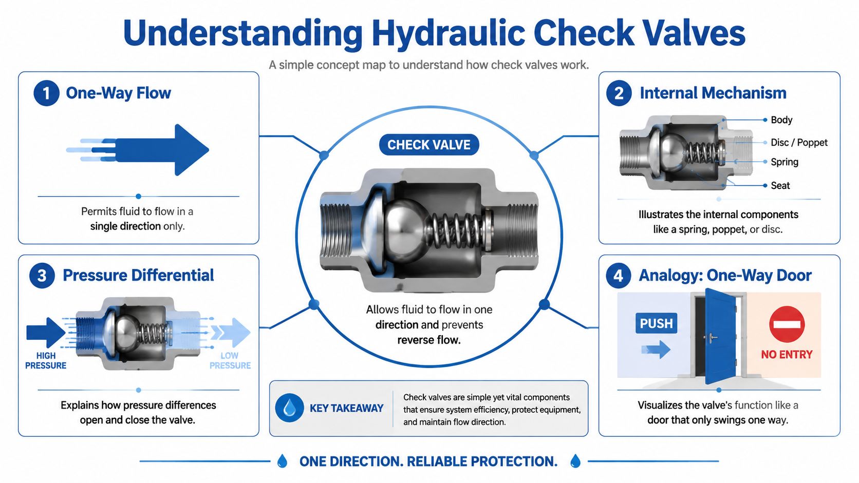
Differential pressure does the work
The operating principle is differential pressure, not magic and not operator timing. Tameson's hydraulic check valve explanation describes it clearly: when inlet pressure exceeds cracking pressure, the poppet, ball or disc lifts off the seat to allow forward flow; when outlet pressure exceeds inlet pressure, the spring forces the internal component back onto the seat to seal and prevent reverse flow.
That tells you two things immediately.
- The valve won't open just because the pump is running. It opens when the pressure difference across it exceeds the opening threshold.
- The valve can shut very quickly. If downstream pressure rises above inlet pressure, the sealing element returns to seat and blocks reverse movement.
Cracking pressure is the key threshold
Cracking pressure is the minimum pressure difference needed to unseat the internal element and create detectable forward flow. IQS Directory's technical overview puts the hydraulic range at 3 psi (0.21 bar) to 350 psi (24.1 bar) depending on size, purpose and design.
That range matters because "one-way flow" isn't a single performance level. A low cracking pressure valve may suit a branch where you want easy opening and minimal resistance. A much higher cracking pressure may be chosen where the valve also contributes to holding behaviour, pilot logic or stability under changing loads.
If you don't know the required cracking pressure, you don't yet know which check valve you need.
Why the internal design changes behaviour
The internals determine how the valve responds in service.
| Internal element | Typical behaviour | What it means in the field |
|---|---|---|
| Ball | Simple lift from seat | Robust and tolerant of basic duties, but seat quality and contamination control still matter |
| Poppet | Positive, direct sealing | Common where tight shut-off and fast response are needed |
| Disc | Broader sealing geometry | Useful where the design calls for compact packaging or specific flow characteristics |
The practical mistake is to think any one-way symbol on a drawing can be satisfied by any one-way valve on the shelf. The fluid only sees geometry, spring force, pressure differential and seat condition. If one of those is wrong, the circuit will tell you.
Comparing Common Check Valve Types
Not all check valves belong in the same hydraulic job. The safest way to choose is to match the valve type to the circuit duty, not just the port size.
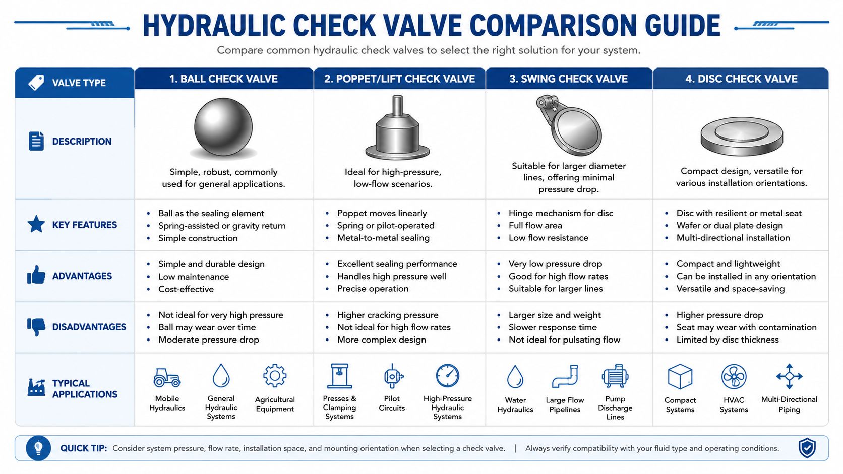
Four common designs you'll meet
The most common forms in hydraulic and adjacent fluid systems are ball, poppet or lift, swing, and disc check valves. The broad specification range is wide. NSW Valve's specification overview describes UK-engineered check valves with nominal diameters from DN15 to DN150, pressure ratings commonly up to 413 bar (6,000 psi) for high-pressure hydraulic applications, and dashpot-assisted designs that can provide controlled closure over 5 to 30 seconds to reduce surge in long pipelines.
Those figures show the range available. They don't mean every style suits every hydraulic manifold.
Practical comparison
| Valve type | Strengths | Trade-offs | Typical fit |
|---|---|---|---|
| Ball check valve | Simple construction, durable, straightforward one-way function | Can be less precise in shut-off behaviour than a well-designed poppet in some hydraulic duties | General inline circuits, basic protection duties |
| Poppet or lift check valve | Fast response, strong sealing, well suited to pressure duty | More sensitive to seat condition and contamination if the application is dirty | Pump protection, manifold blocks, load-related circuits |
| Swing check valve | Low resistance in larger-bore lines, good for freer flow | Not the first choice where rapid hydraulic response and compact high-pressure packaging are critical | Larger lines and adjacent fluid applications where pressure drop matters |
| Disc check valve | Compact, versatile, useful where space is constrained | Performance depends heavily on exact internal design | Mixed installations where packaging and orientation matter |
What works in hydraulic circuits and what doesn't
For high-pressure mobile and industrial hydraulics, the spring-loaded poppet style often makes the most sense because it closes positively and quickly. That's important when you need to protect a pump, isolate a branch, or stop a load circuit from seeing reverse movement.
A swing check can be attractive because of lower pressure drop in larger lines, but it isn't automatically the best option for compact hydraulic manifolds where vibration, rapid cycling and pressure reversals are routine. In those circuits, it may be mechanically acceptable yet functionally clumsy.
Ball check designs sit in the middle. They can be very dependable when correctly matched, but they still need the right seat geometry, pressure range and contamination control.
For a broader view of where these components sit alongside directional, proportional and modular designs, this guide to types of hydraulic valves helps put check valves in context with the rest of the circuit hardware.
A valve that survives pressure isn't necessarily a valve that controls the circuit properly.
A simple selection shortcut
If you're narrowing options quickly, start with these questions:
- Is the duty mainly protection or control? Pump backflow protection and load-related functions usually need a more deliberate hydraulic design than basic one-way flow.
- How clean is the fluid? Fine seat designs reward clean oil. Dirty systems shorten the life of precision sealing surfaces.
- Is the valve in a manifold, cartridge cavity or line? The mounting format often rules out half the catalogue before performance is even compared.
- Will the circuit see shock or reversal? Fast closure and seat integrity matter more when the machine changes state quickly.
Key Performance Parameters to Specify
Most check valve problems start before installation. They start when the specification is too thin.
If the order line says only thread size and pressure rating, you've left out the characteristics that determine whether the valve opens when it should, stays shut when it must, and avoids wasting energy while doing it.
Cracking pressure and why it matters
The first figure to pin down is cracking pressure. Valves Online's check valve data notes that a check valve's cracking pressure is the minimum differential pressure needed to open it, and that UK-standard high-pressure modular check valves are typically calibrated to 0.5 bar (7 psi).
That's a useful reference point, not a universal answer. In service, the wrong cracking pressure creates different faults at both ends:
- Too low, and the valve may allow unwanted movement, poor holding behaviour or nuisance opening during transients.
- Too high, and the valve can starve a low-flow branch, delay actuation, or create avoidable pressure loss and heat.
A gauge reading often settles arguments quickly. If you're diagnosing whether a valve is opening where expected, a reliable hydraulic pressure gauge belongs in the test kit before anyone starts replacing components.
Pressure rating, flow and pressure drop
Pressure rating tells you whether the valve body and internals are suitable for the system's operating and transient pressures. It doesn't tell you how efficiently the valve will pass flow. That's where pressure drop comes in.
A valve can be safe at system pressure and still be a poor choice because it creates too much restriction at the required flow. In practical terms, excess pressure drop means:
- Higher heat generation in continuous operation
- Sluggish actuator performance where every bar counts
- Reduced efficiency across the branch or the whole power unit
This is why catalogue curves matter. If the circuit is flow-sensitive, don't choose purely by port size.
Material and sealing choices
Material selection is less glamorous than pressure figures, but it decides service life.
Use these checks:
- Base material compatibility with the fluid. Mineral oil, water-based fluids and contaminated environments don't treat metals equally.
- Corrosion resistance where machinery lives outdoors, is washed down, or runs in aggressive environments.
- Seal suitability for the fluid and temperature range encountered in operation.
The best valve on paper still fails early if the oil, environment and seal material don't belong together.
The specification sheet should answer these points
Before signing off a part, confirm:
| Parameter | Why it matters |
|---|---|
| Cracking pressure | Determines opening point and affects control behaviour |
| Maximum working pressure | Confirms structural suitability for the circuit |
| Flow capacity | Prevents undersizing and excess pressure loss |
| Mounting style | Ensures the valve fits the manifold, cavity or line arrangement |
| Materials and seals | Protects service life and fluid compatibility |
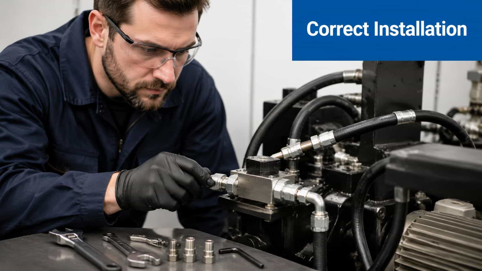
Selection and Installation Best Practices
Selection gets most of the attention. Installation is where many avoidable failures happen.
A check valve can be perfectly specified and still misbehave if it's mounted backwards, fitted into a contaminated line, or installed in a duty it was never certified to handle.
Start with size and duty, not just thread
In wider UK practice, check valves are available across a broad dimensional and pressure range. For applications involving water backflow protection and compliance, the valve class matters just as much as physical fit.
Water Regulations UK guidance on check valves and non-return valves explains that in the UK, check valves are classified under BS EN 12289 and the Water Fittings Regulations. Single check valves provide protection against fluid category 2 backflow, while double check valves are required for fluid category 3 backflow.
That distinction is critical in agricultural and mobile plant applications where hydraulic equipment may interface with water systems, washdown systems or filling arrangements. Compliance isn't optional, and neither is product certification.
Installation mistakes that keep turning up
The field mistakes are usually basic.
- Wrong flow direction. The arrow on the body isn't decoration. Backwards installation gives you instant malfunction and confusing symptoms.
- Dirty assembly. A tiny particle on the seat can turn a new valve into a leaking one.
- Poor location choice. If the valve is placed where line dynamics are unstable, you'll get chatter or delayed response that looks like a component defect.
- Ignoring access for service. If nobody can test, inspect or replace it easily, routine maintenance gets postponed until failure forces it.
A fitter's checklist
Use a short discipline before first start:
- Confirm the orientation against the circuit drawing and body marking.
- Check the mounting interface. Inline, cartridge and modular bodies aren't interchangeable.
- Flush or verify cleanliness before the valve sees live oil.
- Tighten to the correct assembly standard for the fitting and housing type.
- Test the circuit function, not just leakage. A valve can seal and still be wrong for the control task.
Where standards meet practical hydraulics
The compliance side often catches people out because they assume all one-way valves count as backflow protection. They don't. In regulated duties, only valves conforming to the required standard can make that claim.
For OEMs and service engineers, the practical message is simple. Match the valve to the circuit, then match the certification to the application.
Real-World Applications in UK Machinery
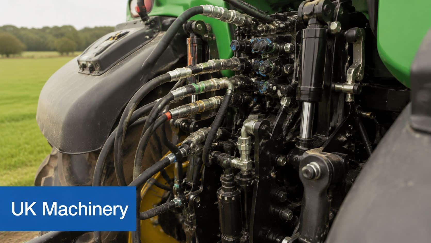
In UK machinery, a check valve earns its place when something must stay put, stay protected, or stay isolated after the operator changes command.
On a tractor rear service or lift-related hydraulic branch, a check valve can stop oil from returning the wrong way when the load changes or when the machine is shut down. That keeps attached equipment from settling unexpectedly and helps maintain predictable behaviour during repeated lifting cycles.
Mobile plant and transport equipment
Tipper bodies, hook loaders and trailer-related hydraulic functions rely on controlled one-way flow more than many operators realise. A check valve may be protecting the pump from reverse pressure on shutdown, holding oil in the intended branch, or preventing part of the circuit from draining back between operations.
If you're dealing with equipment where hydraulic stability and load handling matter, it's worth looking at real platform layouts such as ANTS Trailers drop deck models. The exact trailer design isn't the point. The useful lesson is how equipment geometry, loading conditions and hydraulic duty combine to make backflow control a safety and reliability issue rather than just a component choice.
Industrial power packs and valve stacks
In industrial power packs, check valves often sit in manifold assemblies and pilot circuits. That's where they isolate accumulator lines, stop cross-port interference, and maintain directional stability around CETOP-mounted valve functions.
The reason they get overlooked is that they don't ask for operator input. They must react correctly every time the pressure relationship changes. When they don't, the symptoms spread into the rest of the control system and people start blaming pumps, coils or main directional valves.
This walkthrough gives a useful visual of the component in action:
In real machines, the check valve is often the part that prevents a minor pressure reversal becoming a major mechanical fault.
Troubleshooting Common Check Valve Issues
When a check valve goes wrong, the machine usually gives you a clue before it gives you a stoppage. The trick is reading the symptom in the right order.
Chatter, leakage and sticking
Three faults turn up repeatedly.
- Chatter usually points to unstable flow conditions, unsuitable cracking pressure, or a valve that is too large or too small for the branch duty.
- Internal leakage often comes from contamination on the seat, wear on the sealing surfaces, or damage that stops full reseating.
- Sticking open or closed can come from contamination, varnish, mechanical damage, or cold, viscous oil that changes how the internal element moves.
A useful first step is to isolate whether the problem is mechanical, pressure-related, or contamination-related. Don't pull the valve apart before you've checked what the circuit pressure is doing and whether the symptom appears only at start-up, only under load, or only when hot.
Cold-weather faults in UK machinery
Cold starts are harder on check valves than many specifications admit. A 2025 HEMA study cited in the check valve reference reported that 32% of check valve failures in UK mobile machinery occurred during winter months due to inadequate cracking pressure selection for cold climate conditions.
That aligns with what maintenance teams see in practice. Heavier oil at low ambient temperature changes opening behaviour. A valve that looks acceptable on a warm bench can hesitate, chatter or fail to open properly on a frosty morning.
A quick diagnostic sequence
If the valve is suspect, work through it logically:
- Verify flow direction and installation orientation.
- Check system pressure at the valve location, not elsewhere in the circuit.
- Inspect oil condition and cleanliness.
- Look for seat contamination or wear if the valve is serviceable.
- Compare the symptom at cold start and normal operating temperature.
For broader fault-finding across the surrounding circuit, this guide to hydraulic valve problems is a useful next step.
If the same issue returns after cleaning or replacement, stop blaming the part alone. Recheck the application. Most repeat check valve failures are selection or circuit problems wearing a maintenance disguise.
If you need help choosing the right check valve for a mobile or industrial hydraulic system, speak to MA Hydraulics Ltd. The team can help with component matching, pressure and flow suitability, replacement parts and harder-to-identify hydraulic valve applications. Phone 01724 279508 today, or send us a message.
