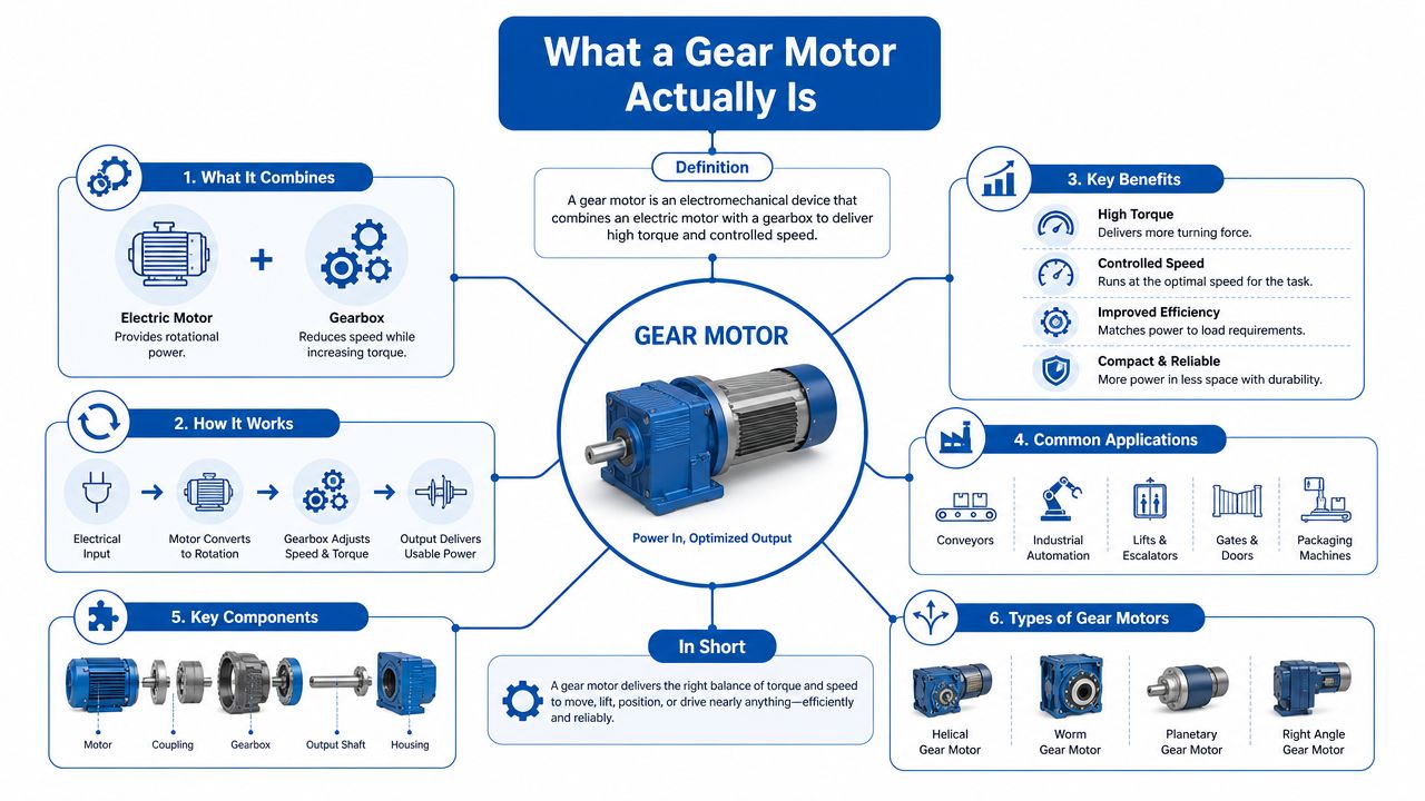
A gear motor is a single compact unit that combines an electric motor with a gearbox, using gears to slow the motor's high rotational speed down to a lower output speed while multiplying torque. In practice, that means a unit that turns 1,200 to 3,600 RPM motor speed into the low-speed, high-force motion many plant and mobile systems need, especially where space is tight and the load is heavy (technical reference).
If you're stood by a conveyor that's started slipping, or you're pricing up a replacement drive for a mixer, loader, or winch, you're probably after the same thing, controlled motion without wasting power or fitting extra hardware. That's where gear motors earn their place, because they package the motor and reduction stage into one assembly instead of asking you to bolt them together separately (integrated unit definition).
What a Gear Motor Actually Is
The quickest way to think about a gear motor is as a motor and gearbox living in one housing. A maintenance engineer replacing a stalled conveyor drive doesn't usually want two separate items, a motor on one line and a gearbox on another. They want one assembly that can be lifted, mounted, aligned, and commissioned without fuss.
A bicycle gear analogy helps here. You pedal fast in a low gear and get more turning force at the wheel, just at a lower speed. A gear motor does the same job inside a sealed drive unit, trading speed for torque so the machine can move a load that a plain motor would struggle to start.
Practical rule: if the driven machine needs low speed and high torque, a gear motor is usually the first place to look.
The integrated design matters on the shop floor. It reduces alignment headaches, keeps the footprint compact, and cuts down on the number of parts procurement has to track. That simplicity is one reason gear motors have become standard across conveyors, mixers, lifting equipment, and automation machinery in British factories, where plant space is often at a premium and the load rarely cares about your preference for neat packaging (gear motor definition and uses).
The wider UK context matters too. Manufacturing accounted for about 9.4% of gross value added in 2023, according to the Office for National Statistics, so compact torque-conversion equipment remains a basic building block in a major part of the economy (ONS manufacturing gross value added).
The Main Parts Inside a Gear Motor
Open a gear motor on the bench and you'll normally see four things doing the work. The electric motor creates rotation, the input shaft carries that rotation into the reduction stage, the gear train changes speed and torque, and the output shaft sends the final motion into the machine. The housing holds everything in line and keeps the assembly rigid.
Motor, shaft, gear train, housing
The electric motor is the prime mover. In many industrial units it's an AC induction motor, chosen because it's durable and familiar to maintenance teams. Its shaft turns at high speed and feeds that motion into the gearbox section, where the ratio does the heavy lifting.
The gear train is where the speed reduction happens. Different gear meshes change the relationship between input and output, which is why the same motor can suit very different duties once the reduction is selected correctly. The output shaft then delivers the slower, stronger motion the application needs.
The housing is more than a cover. It keeps the gears aligned, retains lubricant where needed, and protects the internal parts from dirt and knocks. On real plant, that matters as much as the torque rating, because a neatly designed drive that won't survive the environment is still the wrong drive.
A separately mounted motor and gearbox can work, but it adds alignment work, extra couplings, and another place for tolerances to stack up. The integrated block is often the default on modern UK plant because it's easier to install and keeps the drivetrain shorter.
Bench check: if you can trace power from motor shaft to gear set to output shaft without guessing where the reduction happens, you've got the right mental model.
Common Gear Types and How They Behave
A gear motor can do the same broad job in several different ways, and the gear family changes how it feels in service. Efficiency, torque capacity, noise, cost, and heat build-up all shift with the gear type, so the right choice for a conveyor is not always the right choice for a winch or mixer.
Comparing the main gear families
| Gear type | Typical efficiency | Best for | Watch out for |
|---|---|---|---|
| Spur | Good | Simple drives, light to medium duty equipment | Noise can rise as load and speed increase |
| Helical | Good to very good | General factory conveyors, smooth running plant | Axial thrust needs proper support |
| Bevel | Good | Changes in drive direction, right-angle layouts | More sensitive to alignment and load setup |
| Worm | Lower than many alternatives | Slow-speed mixers, compact reduction in a tight space | Heat and efficiency losses can become important |
| Planetary | Very good | High-torque winches, compact heavy-duty drives | More complex construction and higher component precision |
A spur set is the plainest option, and that is often its strength. It suits straightforward drives where cost and simplicity matter more than quiet running, which is why you still see it on lighter duties and in equipment that does not need refined motion.
A helical arrangement runs more smoothly, because the teeth engage gradually rather than with a sharp bite. On a factory conveyor that starts and stops through the day, that smoother contact helps the drive feel calmer under load. The trade-off is axial thrust, so the bearings and mounting arrangement need to suit the duty.
A bevel arrangement changes the direction of drive, which helps when the motor and output shaft cannot sit in line. That makes it useful on compact machines and angled layouts. A worm gear gives a neat reduction in a small space, but the sliding contact inside the gear set turns more input energy into heat, so it suits slower duties where that loss can be managed.
A planetary unit spreads the load across several gear paths, so it is often chosen for high-torque work where the drive has to stay compact. You will see that approach on heavier winch duties and other applications where the gearbox must carry a serious load without growing bulky. For a wider practical explanation of reduction gearboxes, this reduction gearbox guide is a useful companion read.
Key Specs and Performance Factors
A gear motor gets easier to choose once you stop treating the datasheet like a sales sheet and start reading it as a set of limits the machine will enforce. The figures that matter are the ones that show whether the unit can start the load, hold it in motion, and shed the heat it creates while doing the work.
The figures that decide the job
Output speed is the speed at the shaft after reduction, usually given in rpm. Output torque is the turning force at that shaft, and it tells you whether the drive can move the load without stalling. Gear ratio shows how much speed is traded for torque, so a larger reduction gives a slower output with stronger turning force.
Efficiency matters because every drivetrain loses some energy as heat. On a conveyor that runs for long periods, that heat becomes operating cost and thermal stress, and both can shorten service life if they are ignored. Duty cycle shows whether the unit is expected to run continuously, start and stop often, or work intermittently, and that changes the margin you need in the selection.
Service factor gives extra breathing room between the stated rating and the actual working demand. On a conveyor with shock loading, that margin matters because a quiet start in the workshop can become a rough one when a full belt catches a heavy product. Thermal limits matter just as much, because gearbox heat dissipation has to stay within the manufacturer's limit for safe operation, as shown in the geared motor sizing guidance.
Rule from the shop floor: a drive that meets torque on paper but overheats in service is still the wrong drive.
A quick way to judge the numbers is to match them to the duty, not to the brochure headline. On a continuous-duty agitator, heat control may matter more than peak torque. On a conveyor, the launch condition and torque margin often come first. The same gear motor can suit both jobs, but only if the load cycle, ambient temperature, and expected starts are read together rather than in isolation.
Where Gear Motors Are Used in UK Industry
The places you'll see a gear motor most often are the places where a plain motor would be too fast and too loose with torque. On a food-production conveyor, the drive needs to move product steadily, not sprint and stall. A helical gear motor is a sensible fit there because the motion is smooth and the output speed is predictable.
On a Midlands distribution centre winch, the job is different. The drive may need to pull a load under awkward conditions, often at low speed and with a bit of shock in the system. That's the sort of application where a compact reduction unit earns its keep because the winch needs force first and speed second.
Agricultural machinery asks for another kind of toughness. A loader or handling machine on a Lincolnshire farm can face dust, vibration, stop-start duty and awkward load changes in the same day. A gear motor helps because the torque multiplication is built into the drive, so the machine can do practical work without an oversized motor hanging off the frame.
A small automation cell in a Scunthorpe fabrication shop usually needs something else again, a drive that is easy to package, easy to replace, and happy inside a compact machine envelope. That's why gear motors keep showing up across UK industry, from material handling to plant equipment, alongside the wider manufacturing base that still matters to the economy (UK manufacturing context).
Choosing the Right Gear Motor for Your Application
A plant engineer looking at a conveyor, a loader, or a bespoke power pack has one job before any part number is chosen, match the drive to the duty. If the load is steady, the motor sees a very different life from one that starts hard, stops often, or takes shock through the shaft. That is the point where a gear motor earns its place, because the gearbox shifts speed and torque into a range the machine can use.
Start with what the machine must do, then work back to the drive. The load, the output speed, and the way the machine runs through the day all shape the choice more than the motor frame size on its own.
A practical selection checklist
- Define the load. Identify what the drive is turning, lifting, pushing, or conveying, and note whether the load is steady or shocky.
- Set the output speed. Work out the shaft rpm the machine needs, not the motor speed on its own.
- Calculate the torque. Make sure the output torque covers the duty, then add margin where starts, stalls, or overloads can happen.
- Choose the gear ratio. Pick a ratio that gives the speed you need without forcing the motor into an awkward operating point.
- Check duty cycle and service factor. Continuous running and frequent starting are not the same job.
- Match the mounting. Confirm flange, foot, shaft and orientation before the part number goes to purchase.
- Check the environment. Dust, washdown, vibration and outdoor exposure all shape the final choice.
- Verify heat dissipation. The gearbox's allowable heat dissipation and the dissipated watts must stay within the maker's stated limit.
That heat check matters more than people expect. A unit can look fine on torque and speed, then run too hot because the duty cycle is heavier than the housing can shed. If you want a fuller walk-through of the sizing method, this motor sizing guide is a useful reference, and the same discipline sits behind sizing guidance used by engineers who size drives against real loads, not just nameplate figures.
For the control side, Sheridan Technologies' design expertise is a useful reference point when the electrical control has to sit cleanly with the mechanical spec. That is where junior engineers often get caught out, because the motor may be right in theory but the control arrangement, starting behaviour, or thermal limit can still make the package a poor fit in service.
Write the duty down before you buy anything. Note the start frequency, the load type, the mounting position, and any heat concerns from the cabinet or the machine layout. A simple note like that prevents the common mistake of selecting a unit that looks fine on paper but runs hot once it is bolted into a cramped frame or a dusty enclosure.
Gear Motor vs Direct Drive and Hydraulic Drives
A gear motor is compact and straightforward, but it's not the only way to move a load. Direct-drive motors remove the gearbox and can be very efficient where the motor can be sized to suit the job. Variable-speed drive systems give you more control over speed, but they add electrical complexity and tuning work.
Hydraulic motors sit in a different part of the design space. They're useful when the system already depends on hydraulic power, when the machine needs strong low-speed output, or when layout constraints make a hydraulic circuit the more practical answer. For hydraulic applications, MA Hydraulics' hydraulic motor range is one route engineers may consider when the drive belongs in a fluid-power system rather than a purely electric one.
How the options differ in practice
A gear motor is often the most compact answer when you need fixed ratio, low-speed torque, and simple installation. A direct drive can be cleaner mechanically, but the motor may need to be larger to achieve the same output condition. A VSD-driven motor gives better controllability, but you're relying on the drive electronics as well as the motor. A hydraulic motor can handle demanding duty in a fluid-power machine, but seals, hoses, oil cleanliness and maintenance all sit in the background.
Practical rule: choose the drive that suits the machine's duty, not the one with the shortest datasheet.
There's no universal winner here. If compactness and predictable torque conversion matter most, a gear motor stays highly relevant. If speed control, serviceability or system efficiency dominate, another option may deserve the engineering time.
Installation, Maintenance and Getting Help
Good installation starts with alignment and mounting, because a well-chosen unit can still fail early if it's forced into misalignment or rigidly installed against the machine's natural movement. Check seals, fasteners and shaft coupling condition during fit-up, then watch for vibration, temperature rise and unusual noise once the drive is in service.
Routine inspection should be boring. That's the point. If the housing temperature climbs, the oil seal starts weeping, or the sound changes from smooth to rough, something in the drivetrain has changed and it needs attention before the failure becomes expensive. For engineers comparing service materials and component durability, even something as simple as comparing 304 vs 316 steel tags can be a useful reminder that the machine environment should always shape the component choice.
MA Hydraulics Ltd can help with hydraulic and drive component selection, cross-references, and bespoke power-pack work when the application needs more than a catalogue pick. That's especially useful when the job sits between electrical drive, gearbox choice, and hydraulic integration.
If you're sizing a replacement or specifying a new drive for a conveyor, mixer, loader, or mobile unit, get the application details together first, then talk it through with someone who does this every day. Phone 01724 279508 today or send us a message at https://www.mahydraulics.co.uk/contact-us/.
MA Hydraulics Ltd supplies gear motors, hydraulic components and bespoke power solutions for UK machinery, plant and mobile equipment, with practical support for sizing, cross-references and replacement work. If you need help matching a gear motor to torque, speed, duty cycle or thermal limits, visit MA Hydraulics Ltd and speak to the team about the application before you order.