Think of a hydraulic flow gauge as the speedometer for your hydraulic system. In simple terms, it gives you a live reading of how much fluid is moving through a pipe or component, usually measured in litres per minute (L/min). This single reading is one of the most important vital signs for your machinery’s health.
What Is a Hydraulic Flow Gauge and Why Is It So Important?
Imagine trying to drive your car with no dashboard. You wouldn’t know your speed, how much fuel you have left, or if the engine was overheating. It would be a guessing game, and a dangerous one at that. A hydraulic system without a flow gauge is in the same boat—you’re running it completely blind.
At its heart, a hydraulic flow gauge measures the volume of fluid passing a point over time. But this isn’t just a number on a dial; it’s a direct window into the system’s performance. For any hydraulic circuit to do its job, whether it’s lifting a heavy container or powering a precision press, the right amount of fluid has to get to the right place at exactly the right time.
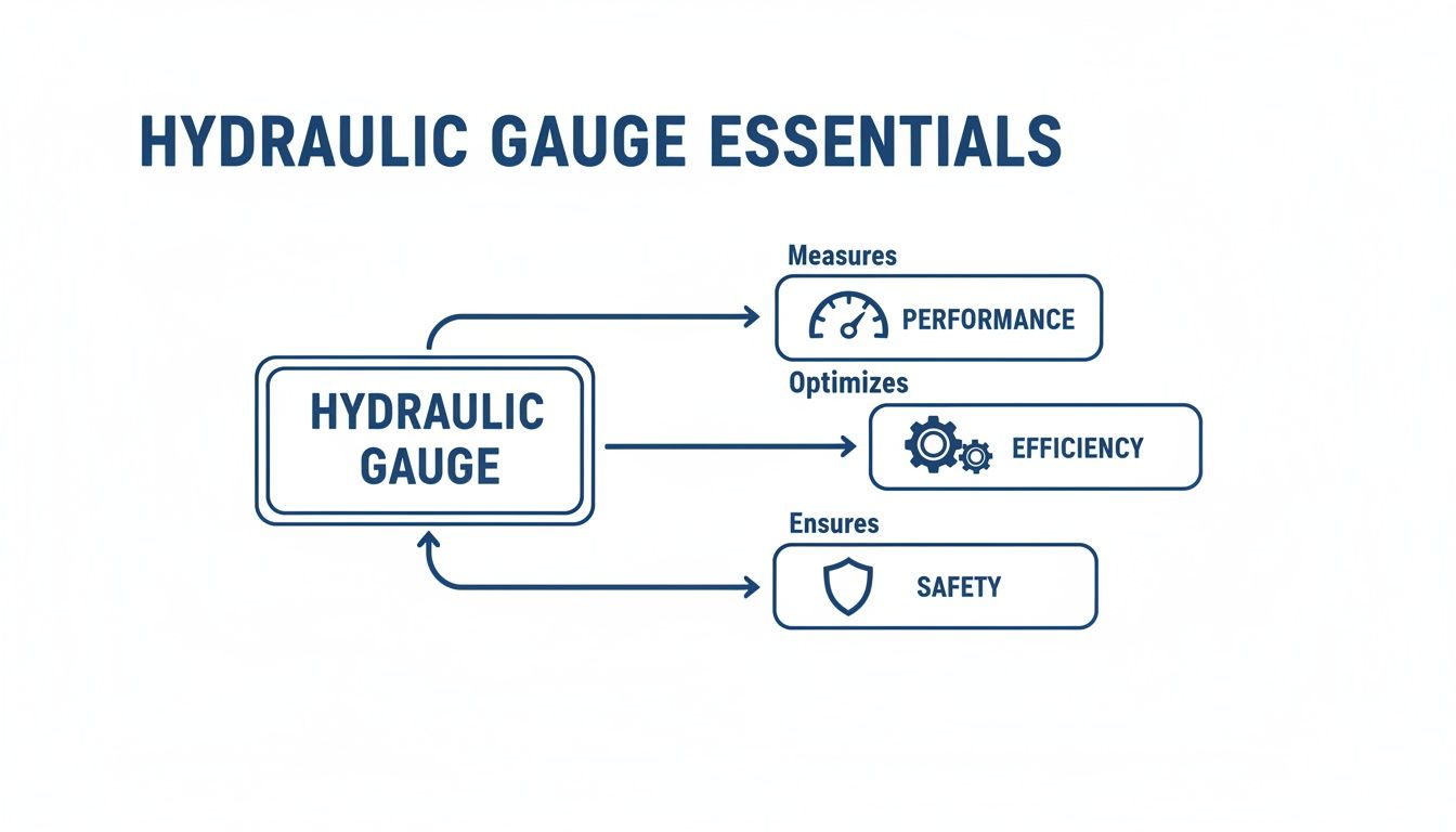
The Three Pillars of Hydraulic Health
A flow gauge is absolutely essential because it helps you keep an eye on the three pillars of a healthy hydraulic system: performance, efficiency, and safety. It gives you clear, immediate feedback, taking you from guesswork to making decisions based on solid facts.
Performance Monitoring: The gauge instantly tells you if your pump and other components are delivering the flow they’re supposed to. A drop in flow rate, even when the pressure seems fine, is often the first warning sign of internal leaks or component wear, long before a complete failure happens.
Efficiency Optimisation: Inefficient systems burn through energy and money. By showing you where flow is being lost or restricted, a gauge helps you fine-tune the circuit to cut down on energy waste and reduce your running costs.
Safety Assurance: The wrong flow can cause all sorts of problems, from jerky actuator movements and overheating to dangerous pressure spikes. Monitoring the flow ensures the equipment stays within its safe operating limits, protecting both the machine and the people using it.
Without this insight, troubleshooting becomes a long, frustrating process of swapping out parts until you find the culprit. A problem you could pinpoint in minutes with a flow gauge might otherwise take hours of downtime to diagnose. This is why understanding how all the components work together in a complete system, like a hydraulic power unit, is so crucial for proper maintenance.
Ultimately, a hydraulic flow gauge is far more than a simple measuring device. It’s a fundamental tool for proactive maintenance, accurate diagnostics, and ensuring your machinery is reliable day in, day out.
Understanding How a Hydraulic Flow Gauge Works
To really get to grips with a hydraulic flow gauge, it helps to know what’s actually going on inside the thing. It’s not some magic box; the principles are surprisingly straightforward, relying on clever mechanical or electronic designs to measure how fluid is moving. Once you understand the basics, you can interpret the readings far more effectively and get a real feel for your system’s behaviour.
At its core, a hydraulic flow gauge is there to answer one simple question: how much fluid is passing this point, right now? To figure that out, it needs to detect the fluid’s movement and turn that into a clear measurement, usually in litres per minute (L/min). Think of it like a small water wheel in a stream – the faster the water flows, the quicker the wheel spins. It’s the same idea, just with hydraulic oil.
This is why it’s so critical. By measuring flow, you get a direct window into your system’s performance, allowing you to fine-tune its efficiency and, crucially, keep things running safely.
The Turbine Mechanism
One of the most common designs you’ll come across uses a small, finely balanced turbine (or impeller) placed right in the path of the fluid. As the hydraulic oil flows through the gauge, it spins the turbine blades. The speed of that rotation is directly linked to the flow rate of the oil.
A magnetic sensor then picks up how fast the turbine is spinning. This signal is then converted into the flow rate you see on the dial or digital display. It’s a reliable and proven method that gives accurate readings across a wide range of flows, which is why it’s a firm favourite for everything from portable test kits to permanently installed meters.
Positive Displacement Principles
Another popular method is positive displacement. Picture a revolving door that only moves when someone pushes through it. A positive displacement gauge operates in a similar way, using a pair of tightly meshed gears or rotating pistons that form sealed chambers.
Fluid comes in, gets trapped in these little chambers, and is forced out the other side as the gears turn. Because each full rotation moves a very precise, known volume of fluid, the gauge just has to count the rotations to calculate the flow rate. This technique is incredibly accurate, particularly when you’re measuring lower flow rates or working with thicker, more viscous fluids.
It’s easy to mix them up, but pressure and flow are not the same thing. Pressure is the force pushing within the system (measured in bar), while flow is the amount of fluid being moved. They are two separate, but equally vital, signs of a system’s health.
The Variable Orifice Method
Finally, you have the variable orifice gauge, sometimes called a differential pressure gauge. This one works on a simple concept: when you force fluid through a restriction, you create a pressure drop. Inside this type of gauge, there’s a spring-loaded piston or cone.
As the fluid flow increases, it pushes this piston back against the spring, which opens up a wider gap (the orifice) for the oil to pass through. The piston’s position directly corresponds to the flow rate, which is indicated on a calibrated scale. It’s a tough, cost-effective design that’s brilliant for fieldwork where you need a reliable indication of flow without needing pinpoint precision.
Knowing how these gauges work takes the mystery out of flow measurement. It shows how a simple mechanical or electronic process can give you the critical data needed to keep your hydraulic system running smoothly and efficiently.
For expert advice on picking the right gauge for your setup, give us a call on 01724 279508 or send us a message today.
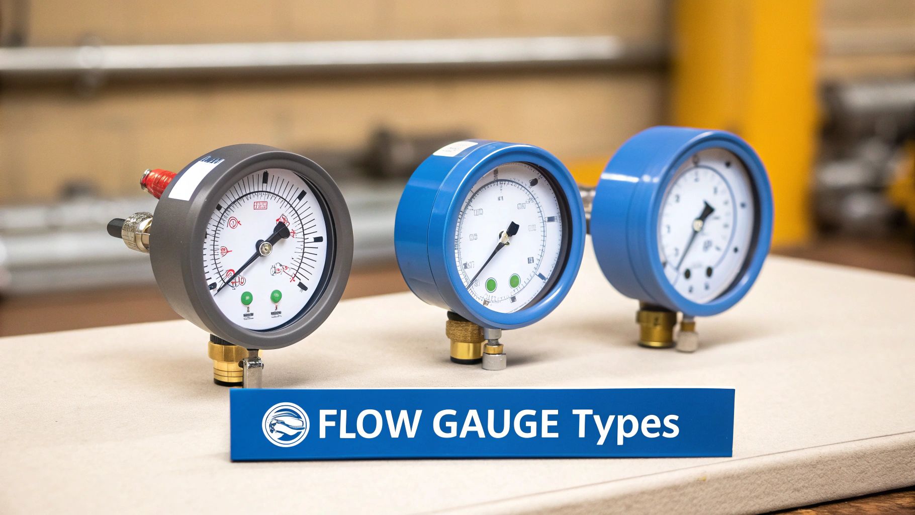
Exploring the Main Types of Hydraulic Flow Gauges
Choosing the right hydraulic flow gauge isn’t a one-size-fits-all situation. Just as you wouldn’t use a delicate jeweller’s screwdriver to assemble heavy machinery, you need the right tool for the job. Getting to grips with the main types of gauges is your first step towards making a smart, effective decision.
Broadly speaking, flow gauges fall into a few key categories, usually defined by how they work and where they’re used. You’ll typically come across mechanical, electronic, and permanently installed inline meters. Each has its own distinct advantages and is built for specific environments and tasks.
Mechanical Analogue Gauges
Think of mechanical gauges as the trusty, rugged workhorses of the hydraulics world. Most operate on a variable orifice principle, where the flow of hydraulic fluid pushes a piston against a calibrated spring. The distance the piston moves directly corresponds to the flow rate, which you can read clearly on an analogue dial.
Key Advantage: Their biggest plus is their sheer simplicity and durability. With no batteries or electronics to fail, they are incredibly robust and perfectly suited for tough field conditions. They can take the knocks, dirt, and vibration that come with working on mobile machinery.
Best For: On-the-spot troubleshooting out in the field. If you’re a maintenance engineer working on agricultural, construction, or plant equipment and need a quick, reliable flow reading, a mechanical gauge is an absolute must-have in your toolkit.
Electronic Digital Gauges
When you need a higher degree of precision and the ability to log data, electronic (or digital) gauges are the way to go. These devices often use a small turbine; as fluid flows through, it spins an impeller. A sensor measures its rotational speed and converts that into a highly accurate digital reading.
This level of precision is vital. The UK’s fluid power industry, valued at around £1.2 billion, relies heavily on accurate hydraulic measurement. Hydraulics commands a dominant 80% share of this market, or £960 million, underlining just how critical precise flow gauges are in manufacturing, farming, and mobile machinery. You can dig deeper into these industry stats over at the British Fluid Power Association (BFPA).
Key Advantage: They offer pinpoint accuracy and the ability to connect to data loggers. This is fantastic for monitoring performance over time, allowing engineers to spot subtle performance drops or intermittent faults that a quick spot-check would easily miss.
Best For: System commissioning, performance validation, and in-depth diagnostics in a workshop or lab. They are essential for testing and fine-tuning complex systems where exact flow rates are non-negotiable.
A common misconception is that higher accuracy is always better. While digital gauges offer incredible precision, the sheer ruggedness and straightforward nature of a mechanical gauge often make it the more practical and cost-effective tool for day-to-day field diagnostics.
Inline Flow Meters
Unlike the portable gauges used for temporary checks, inline flow meters are designed to be a permanent part of the system. They are plumbed directly into the hydraulic circuit’s pipework to give you a continuous, real-time picture of the flow rates. These can be either mechanical or electronic in their design.
Think of an inline meter as a permanent part of the machine’s dashboard, constantly feeding back vital information on its health. This is incredibly valuable in automated industrial processes where consistency is everything.
Key Advantage: They provide constant system monitoring, which opens the door to predictive maintenance and immediate fault alerts. This can be the difference between a minor adjustment and a catastrophic failure, drastically cutting down on unplanned downtime.
Best For: Critical industrial machinery, hydraulic power packs, and any automated system where a stable flow rate is essential for operational safety and product quality.
To help you decide at a glance, here’s a quick comparison of the main types.
Comparison of Hydraulic Flow Gauge Types
| Gauge Type | Principle of Operation | Key Advantage | Best For |
|---|---|---|---|
| Mechanical Analogue | Variable orifice (piston and spring) | Extremely durable, simple, no power required | Field diagnostics, mobile machinery, harsh environments |
| Electronic Digital | Turbine or paddlewheel with a sensor | High accuracy, data logging capabilities | Workshop testing, R&D, system commissioning |
| Inline Flow Meter | Can be mechanical or electronic | Continuous, real-time monitoring | Permanent installation in critical industrial systems |
Ultimately, choosing the right type of hydraulic flow gauge boils down to what you need it for—whether it’s the go-anywhere toughness of a mechanical gauge, the pinpoint accuracy of a digital device, or the constant vigilance of an inline meter.
If you need a hand selecting the perfect gauge for your application, phone us on 01724 279508 today, or send us a message.
Key Specifications to Consider When Selecting a Gauge
Choosing the wrong hydraulic flow gauge is a bit like picking the wrong size spanner for a critical bolt; it’s a mistake that can lead to inaccurate readings, system damage, or costly downtime. The goal isn’t just to find the “best” gauge on the market, but to find the right one for your specific job.
Getting this right is crucial for the countless industries that rely on hydraulic systems every day. The UK flow meter market, which includes these essential gauges for power units and manifolds, is a significant sector driven by constant demand in everything from agriculture to materials handling. This really shows how vital precise monitoring tools have become in modern hydraulics. You can find more insights on the flow meter market on Grandview Research.
By working through a few key parameters, you can sidestep common pitfalls and pick a gauge that will give you reliable performance for years to come.
Flow Rate Range and Accuracy
First up, the most fundamental spec: the flow rate range, measured in litres per minute (L/min). The gauge you choose must be able to comfortably measure both the lowest and highest flow rates your system hits during normal operation. A gauge with a range that’s too low will be overwhelmed, while one with a range that’s too high won’t give you the granular detail you need for diagnostics at lower flows.
Hand-in-hand with range is accuracy. This is usually shown as a percentage of the full-scale reading (e.g., ±2%). For general troubleshooting out in the field, a standard mechanical gauge will often do the trick. But if you’re commissioning a new system or hunting down a subtle performance issue, the pinpoint precision of a digital gauge is invaluable.
Maximum Pressure Rating
Every hydraulic flow gauge has a maximum working pressure rating, measured in bar. This is a critical safety number you absolutely cannot ignore. Your gauge’s pressure rating must be higher than the maximum operating pressure of your system, and that includes accounting for any potential pressure spikes.
It’s worth remembering that a system’s peak pressure is often controlled by a hydraulic pressure relief valve. Knowing how these valves function is key to ensuring the whole circuit is protected. You can learn more in our guide on hydraulic pressure relief valves.
Pushing a gauge beyond its pressure rating can cause it to rupture. This creates a serious safety hazard from high-pressure fluid jets and can lead to catastrophic equipment failure. Always, always check your system’s maximum pressure before you buy.
Fluid Compatibility and Port Size
Not all hydraulic fluids are created equal. You need to be sure that the materials used to build the gauge—especially the seals and the body—are compatible with the type of hydraulic oil or fluid you’re using. An incompatible gauge can quickly lead to problems:
- Seal Degradation: The wrong fluid can cause seals to swell, shrink, or completely break down, resulting in leaks.
- Corrosion: Some fluids can corrode the gauge’s internal parts, wrecking its accuracy and structural integrity over time.
- Contamination: As a gauge deteriorates, it can release particles back into your hydraulic system, damaging other expensive components.
Finally, double-check the port size and type. Here in the UK, BSPP (British Standard Pipe Parallel) threads are the standard. The port size on your gauge has to match your hydraulic hoses or pipework perfectly to get a secure, leak-free connection. Mismatched threads are a common and easily avoidable installation mistake.
By systematically ticking off these specifications, you can confidently choose a hydraulic flow gauge that is perfectly suited to your application.
For expert help matching a gauge to your system’s specific needs, give us a call on 01724 279508 today, or send a message through our contact page at https://www.mahydraulics.co.uk/contact-us/.
Installing and Maintaining Your Flow Gauge
A hydraulic flow gauge is only as good as its installation. You can have the most precise, high-spec device on the market, but if it’s not fitted correctly, you’ll get unreliable readings every time. Getting the installation and routine maintenance right is what turns a simple gauge into a trustworthy diagnostic tool, helping you keep downtime to a minimum and performance at its peak.
Getting it right from the very start heads off a whole host of common problems. It’s not just a case of connecting a few hoses; you’re creating the perfect conditions for the fluid to pass through the gauge smoothly. This is crucial for ensuring the internal mechanism—whether it’s a turbine or a piston—can do its job exactly as it was designed to.

Crucial Installation Steps
To get accurate, repeatable results from your new flow gauge, it pays to follow a few best practices during installation. Taking a few extra minutes here will genuinely save you hours of head-scratching and troubleshooting later on.
Ensure Straight Pipe Runs: Always give the gauge a straight, clear section of pipe or hose on both its inlet and outlet. Think of it like a runway for the fluid. A good rule of thumb is to allow a straight length of at least 10 times the pipe’s diameter upstream (before the gauge) and 5 times the diameter downstream (after it). This simple step is vital for preventing turbulence from nearby bends or valves, which is a classic cause of erratic readings.
Check Flow Direction: It might sound obvious, but it’s a common mistake. Most flow gauges are unidirectional. Always look for the arrow marked on the gauge’s body and make absolutely sure it’s pointing in the same direction as the fluid flow in your circuit. Installing it backwards will either give you no reading at all or, worse, could damage the internal components.
Seal Connections Correctly: Leaks are the enemy of any hydraulic system, and a new component introduces new potential leak points. Use the correct thread sealant or bonded seals for your connections and tighten them to the manufacturer’s recommended torque. It’s a balancing act—overtightening can damage the threads, but under-tightening will guarantee a leak.
A Simple Maintenance Schedule
Regular checks are the key to keeping your gauge in top working order. By adding these simple tasks to your routine maintenance plan, you’ll extend its life and ensure it stays accurate.
- Weekly Visual Inspection: Just a quick look-over. Check the gauge for any obvious signs of damage, like cracks in the casing or dial, and keep an eye out for any fluid weeping from the connections.
- Monthly Connection Check: With the system safely depressurised, give the fittings a gentle check to ensure they are still secure. System vibration is sneaky and can cause connections to loosen over time.
- Annual Calibration: For any gauge used in a critical application, it’s wise to have it professionally calibrated once a year. This is the only way to be certain its accuracy holds up against a known standard. For other components like flow dividers, understanding their function is key to maintenance; for more information, you can explore our flow divider instructions.
Common Troubleshooting Guide
If you start seeing odd behaviour from your flow gauge, this quick guide should help you diagnose and sort out the most common issues.
| Symptom | Possible Cause | Solution |
|---|---|---|
| No Reading or Zero Flow | Gauge installed backwards | The first thing to check. Verify the flow direction arrow on the gauge body and reinstall it the correct way around. |
| Blockage in the hydraulic line | Inspect upstream hoses and filters for any blockages or collapsed lines and clear the obstruction. | |
| Erratic or Unstable Readings | Air trapped in the system (aeration) | Air bubbles wreak havoc on readings. Bleed the system properly to remove all trapped air. |
| Insufficient straight pipe run | The flow is turbulent. If possible, re-plumb the gauge to give it the straight pipe length it needs. | |
| Leaking Connections | Damaged seals or threads | Depressurise the system, disconnect the gauge, and carefully inspect the seals and threads for wear. Replace any damaged parts. |
| Incorrectly tightened fittings | Check and tighten the connections to the manufacturer’s specified torque. Don’t just guess. |
By following these straightforward installation and maintenance steps, you can be confident that your hydraulic flow gauge will remain a reliable and valuable tool for diagnosing and monitoring your machinery.
For further assistance or to discuss your hydraulic component needs, phone 01724 279508 today, or send us a message.
How We Can Help You Find the Right Hydraulic Parts
Trying to navigate the world of hydraulic components can feel like a maze, but you don’t have to go it alone. Here at MA Hydraulics, we’ve built our reputation on turning deep technical expertise into practical, real-world solutions that work for your machinery. We do more than just shift boxes; we become your partner in finding the perfect component for your exact needs.
Whether you’re specifying a hydraulic flow gauge for a heavy-duty piece of mobile plant or designing a complex industrial power pack from the ground up, our team is here to offer friendly, knowledgeable support at every stage. We get that finding the right part isn’t just about matching a serial number—it’s about locking in reliability and performance for the long haul.
Your Dedicated Hydraulic Solutions Provider
Think of us as a natural extension of your engineering team. We take the time to really get under the skin of your application, helping you select the right components for peak efficiency and a long, trouble-free service life. Our close relationships with leading manufacturers like Vivoil and Hydronit mean we can source high-quality, dependable parts you can count on.
What really sets us apart, though, is our knack for tracking down those hard-to-find components and providing cross-references when you’re in a tight spot. We genuinely enjoy solving the problems that others can’t.
We are committed to being more than just a supplier. Our goal is to be your trusted partner, providing expert advice and reliable components that keep your operations running smoothly and efficiently.
Expertise Backed by Industry Insight
Our advice isn’t just based on product sheets; it’s grounded in a solid understanding of the UK hydraulics market. The sector is valued at around £960 million, which makes up a massive 80% of the total fluid power industry in the country. This really drives home how vital precise flow measurement is in the hydraulic circuits and manifolds we work with every day. You can read more about the UK hydraulics market at Research and Markets.
This industry-wide view allows us to recommend the most effective and reliable solutions, whether you need a single replacement part or a complete bespoke system build. We’re here to deliver the components and the support you need to succeed.
Your Hydraulic Flow Gauge Questions Answered
Even when you’ve got the basics down, practical questions about hydraulic flow gauges always pop up. We get these all the time from engineers, technicians, and maintenance crews on the ground. Here are some straightforward answers to the most common queries we hear, helping you use your equipment with confidence.
Getting these details right is what makes the difference between a system that runs smoothly and one that’s a constant headache.
How Often Do I Need to Calibrate My Hydraulic Flow Gauge?
This is a big one. For any gauge used in critical applications—where you absolutely rely on that number being correct—we strongly recommend a professional calibration at least once a year. This check squares its readings against a known, traceable standard, giving you confidence in the data you’re using for system diagnostics.
Now, if it’s a general-purpose gauge you just use for occasional fieldwork, you might be able to stretch that out. But, if the gauge is ever dropped or you start to question its readings, get it checked immediately. At the end of the day, regular calibration is the only way to be certain your measurements are accurate.
Can I Install a Flow Gauge in Any Position?
That’s a critical installation question, and the short answer is: no, not always. The right orientation depends entirely on the gauge’s design. Many traditional mechanical gauges, especially the spring-loaded piston types, must be installed horizontally. This stops gravity from messing with the internal mechanism.
If you install one of those vertically, gravity will either pull down on the piston or fight against it, throwing your readings way off. Turbine-style electronic gauges, on the other hand, are generally less fussy about their orientation.
Your first port of call should always be the manufacturer’s installation manual. It’s the ultimate source of truth and will tell you the exact orientation needed to get accurate, repeatable results from your hydraulic flow gauge.
What’s the Difference Between a Flow Gauge and a Flow Switch?
It’s easy to mix these two up, but they have completely different jobs. A hydraulic flow gauge is a measuring tool. It gives you a continuous, variable reading of the flow rate in litres per minute—think of it like the speedometer in your car, giving you precise, real-time information.
A flow switch, however, is just a trigger. It doesn’t measure the amount of flow; it simply confirms whether the flow is above or below a certain set point. It’s a simple on/off device, like a low-fuel warning light on your dashboard. You’d use a flow switch to sound an alarm or shut down equipment if the flow rate hits a dangerously low or high level.
For friendly, expert advice on any hydraulic components, give us a call on 01724 279508 today, or send us a message online.
Ready to Talk Hydraulics? Let’s Find the Right Solution
Getting the most out of your hydraulic system—whether that’s peak efficiency or bulletproof safety—often comes down to one thing: accurate measurement. And that starts with choosing the right hydraulic flow gauge.
If you’re selecting a component, designing a new system from the ground up, or trying to figure out a tricky performance issue, our team is here to help. We’ve seen it all in industrial and mobile applications and can offer straightforward, practical advice to find a solution that’s both reliable and makes sense for your budget.
Phone 01724 279508 today, or send us a message https://www.mahydraulics.co.uk/contact-us/
