
You've got a machine stopped, a replacement marked “1 inch”, and a fitting that looks almost right. The old hose may have carried hydraulic oil, water, or another working fluid, but the label alone doesn't tell you whether the replacement will handle the pressure, route around the machine, or seal correctly. In UK trade language, hose 1 inch identifies a nominal bore. It isn't a complete specification.
That distinction matters across agricultural machinery, mobile plant, irrigation and industrial systems. A reliable replacement starts with the actual flow, pressure, hose construction, bend radius and end connections. The figures below reflect common UK sizing practice, but the final selection still needs to match the manufacturer's data for the exact hose and fitting combination.
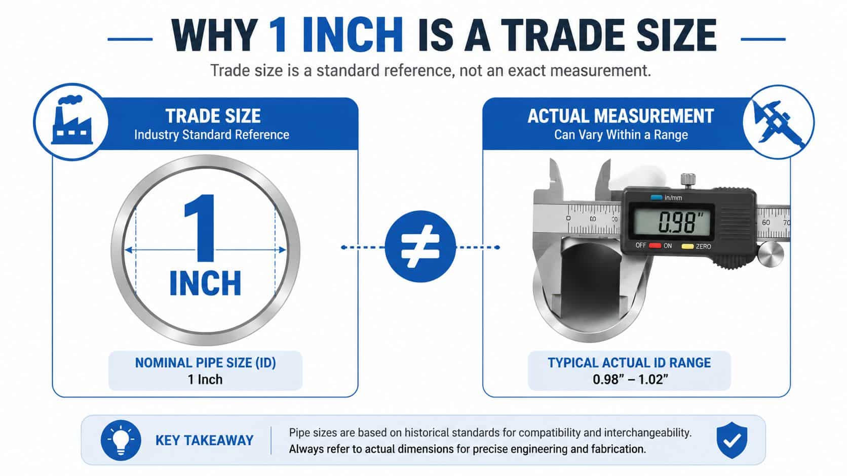
Why 1 Inch Is a Trade Size, Not a Measurement
A customer asking for a 1 inch hose may be specifying only the nominal bore. In UK hydraulic and irrigation work, that trade label commonly points to a 25 mm bore, while hydraulic catalogues often list a nominal 1 inch internal diameter as 25.4 mm. Neither figure describes the complete assembly. Reinforcement, cover, hose standard and pressure class all change the outside diameter, stiffness and bend radius.
UK pipe sizing developed around nominal dimensions rather than one consistent modern outside diameter. British Standard Pipe fittings follow a separate thread-sizing convention. The British pipe thread background explains that a 1 inch BSP thread has an outside diameter of approximately 33.25 mm, with 28 mm nominal pipe equivalence in UK plumbing references. That thread measurement is not the hose bore.
The distinction matters on agricultural machinery, JCB and Massey Ferguson loader circuits, sprayer booms, irrigation headers and industrial equipment. A hose described as 1 inch may connect to a smaller port through a reducer or coupling. The end connection therefore does not necessarily show the hose bore through the entire assembly.
How the UK codes relate
Hydraulic hose catalogues commonly identify a 1 inch nominal bore as -16 dash size, while metric specifications use DN25. The dash reference comes from sixteenths of an inch, so -16 corresponds to 16/16 inch, or 25.4 mm. DN25 describes the nominal metric size. Both labels help identify bore, but neither confirms reinforcement, working pressure or construction.
That is why a 1 inch 1SN hose and a 1 inch 4SH hose should not be treated as interchangeable. The bore label may match, yet the reinforcement, pressure capability, stiffness and minimum bend radius can differ substantially. Choose the pressure class and construction for the circuit, then check whether the hose can be routed without forcing a tight bend.
Practical rule: Treat “1 inch” as a starting reference. Confirm the bore, pressure class, construction, bend radius, fluid compatibility and end connection before approving the assembly.
The size code connects UK inch, dash, DN and BSP terminology, but it does not complete the specification. That interpretation prevents a hose being selected by bore alone when the failure risk lies in pressure class, routing or the fitting arrangement.
Sizing a 1 Inch Hose for Flow and Pressure
A customer asking for a 1 inch hose may be describing a high-flow pressure line, a return line or a mobile-plant circuit. Confirm the duty before checking price or availability. A UK hydraulic training example uses 70 L/min at a recommended velocity of 3 m/s with a 25 mm, 1 inch bore hose assembly. The BFPA hydraulic hose training material shows why bore, flow and line velocity must be considered together.
Use this sequence:
- Record the required flow in L/min.
- Calculate the expected velocity through the proposed bore.
- Compare it with the acceptable velocity for the line function.
- Check working pressure, temperature, fluid compatibility and routing limits.
- Move up a dash size if velocity is too high.
Pressure and return lines can have different velocity targets, depending on the circuit and equipment design. A generic velocity band cannot replace the manufacturer's information. If the calculated velocity is too high, choosing a higher pressure class will not remove the restriction. Increase the bore instead.
Quick reference for a 1 inch hose
The table is a starting point, not approval for an assembly. Acceptable flow depends on line function, fluid, temperature, hose length and the permitted pressure drop.
| Dash Size | Metric DN | Nominal Bore (mm) | Flow Range (L/min) | Typical Use |
|---|---|---|---|---|
| -16 | DN25 | 25.4 | Application-dependent | High-flow pressure, return and mobile plant circuits |
For a worked calculation, use the hydraulic flow-rate calculation guide, then check the result against the hose manufacturer's technical data.
Working pressure is a separate selection gate. One catalogue example of EN 853 1SN at 1 inch lists 88 bar maximum working pressure, a 300 mm bend radius and a 1275 psi burst figure in the UK training data. That example does not approve every 1SN assembly. A 1 inch hose can share the same bore while using a different construction, pressure class and routing envelope.
Allow for pressure pulsation, temperature derating and installation movement. Specify the hose for the circuit's maximum operating pressure and foreseeable spikes, not only its normal gauge reading. The final check should also confirm that the selected -16, DN25 hose and BSP or other end connection match the complete assembly.
Comparing 1 Inch Hose Constructions
The construction determines what a 1 inch hose can tolerate. A single-wire braided hose, a two-wire braided hose and a multi-spiral hose may all have a 25.4 mm bore, yet differ in pressure capability, stiffness, outside diameter and routing behaviour.
EN 853 1SN is often selected for lower-pressure hydraulic duties where its construction and routing characteristics suit the machine. Published UK examples show 88 bar working pressure for a 1 inch 1SN hose, with 300 mm minimum bend radius in one product reference. The BS EN 853 1SN example also lists 352 bar burst pressure for that particular product specification. Don't transfer those figures to another manufacturer without checking its datasheet.
EN 853 2SN uses additional reinforcement and is intended for higher-pressure service than 1SN in comparable sizing. The exact rating depends on the manufacturer, hose series and fitting system, so the construction name alone isn't enough to approve an assembly.
EN 856 4SH uses four spiral wire layers and is designed for demanding high-pressure applications. A UK-supplied 1 inch 4SH product lists 380 bar maximum working pressure, 1520 bar burst pressure and a 340 mm bend radius for a stated 40 m coil specification. The 4SH product data illustrates the trade-off clearly. Higher pressure capacity comes with greater stiffness and more space needed for routing.
| Construction | Standard | Working Pressure @ 1″ (bar) | Min Bend Radius (mm) | OD (mm) | Weight (kg/m) |
|---|---|---|---|---|---|
| 1SN | EN 853 1SN | 88 in the cited example | 300 in the cited example | Manufacturer-specific | Manufacturer-specific |
| 2SN | EN 853 2SN | Manufacturer-specific | Manufacturer-specific | Manufacturer-specific | Manufacturer-specific |
| 4SH | EN 856 4SH | 380 in the cited product data | 340 in the cited product data | Manufacturer-specific | Manufacturer-specific |
Do not buy on bore alone: Pressure class, bend radius and fitting compatibility decide whether the hose will work in the machine.
ISO and manufacturer documentation should be checked for the exact size and series. The ISO hydraulic hose standard listing is a useful standards reference, but it doesn't replace the supplier's product datasheet. A 4SH hose routed through a tight space may be a poor practical choice despite its pressure capability, while a 1SN hose may be wholly unsuitable for a high-pressure circuit.
Choosing Fittings and End Connections
Start with the machine port and identify its thread before selecting the hose end. UK-built plant may use BSPP, a parallel thread normally sealed with a bonded washer or O-ring, or BSPT, a tapered thread more often found in pipework and lower-pressure arrangements. A nominal 1 inch BSP connection can have an outside thread diameter of approximately 33.2 mm and 11 threads per inch, so the fitting size does not equal the hose's 25.4 mm bore.
Measure the male thread with a vernier caliper, then confirm its form and pitch with a thread gauge or a known fitting. A similar-looking metric, JIC, ORFS or flange connection may screw into place without forming a safe seal. Check the port standard, sealing method and end geometry together.
Connection choices that affect safety
For high-pressure 2SN and 4SH assemblies, use the crimped fitting system specified for that hose construction. Some systems require skiving, while others use non-skive ferrules. Reusable worm-drive fittings are not suitable for 4SH service, and a clamp that feels tight does not establish a safe hydraulic rating.
A lower-pressure 1SN water or suction assembly may accept swaged or reusable ends if the manufacturer permits them. Compare the fitting's published working pressure with the hose rating, then follow the specified crimp diameter, insertion depth and machine setting. The hose can be correctly selected and still become unsafe through the wrong ferrule.
| Hose Dash Size | Hose Bore (mm) | BSP Size (in) | BSP OD (mm) | BSP TPI | Typical Fitting Type |
|---|---|---|---|---|---|
| -16 | 25.4 | 1 | 33.2 | 11 | BSPP, BSPT or application-specific adaptor |
| -20 | Application-specific | 1 1/4 | Manufacturer-specific | Manufacturer-specific | Stepped hose tail where the hose specification permits |
Use the hydraulic fittings types guide to distinguish BSP, JIC, ORFS and flange options. Material affects service life and compatibility. Carbon steel suits many general installations, stainless steel 316 is useful in corrosive environments, and brass can suit selected lower-pressure or fluid applications.
Specify the end geometry required by the port, such as a 37-degree flare, JIC, ORFS, or Code 61 or Code 62 flange. Set both ends in their final orientation before crimping. Twisting a completed hose to align the fittings transfers torsion into the reinforcement and can shorten its service life.
Installing and Testing a 1 Inch Hose
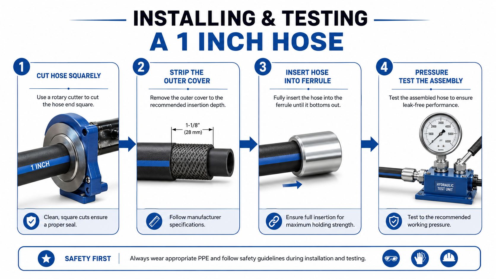
Cut the hose squarely with a dedicated hose saw or rotary cutter. A hacksaw blade used on its own leaves a ragged end, contaminates the assembly and can prevent the ferrule from seating properly. After cutting, clean the hose and strip the cover only to the depth specified for the fitting system.
Skive or non-skive preparation depends on the ferrule and hose construction. Use the correct stripping tool, insert the hose to the required depth, and crimp to the diameter and reduction stated on the fitting datasheet. Check the finished crimp with a micrometer. Even a small dimensional error can reduce service life, particularly on high-pressure spiral-wire hose.
Route before you tighten
Lay the hose through its intended path before tightening the ports. Respect the manufacturer's minimum bend radius, keep the hose from rubbing on moving parts and prevent twist at the fittings. A hose that's pulled tight across a moving joint will fail sooner than one with planned slack and controlled support.
Use rubber-lined P-clips or P-clamps to prevent cover damage. Support spacing depends on hose weight, movement and vibration, so follow the machine or hose manufacturer's routing guidance rather than relying on a fixed spacing rule. Keep the assembly clear of heat sources, sharp edges and pinch points.
The hose should move in the bend, not twist along its length. Orient angled fittings correctly during assembly, and use an elbow or swivel where the routing demands it rather than forcing the hose into a sharp turn.
Pressure-test the completed assembly before commissioning. Hydraulic testing should be performed with suitable guarding, clean test equipment and a controlled exclusion zone. Test pressure and hold time must follow the applicable quality procedure and assembly manufacturer's instructions, then inspect for weeping, movement, cover damage and fitting distortion.
Tag the hose with its assembly details, pressure class and test information where your traceability system requires it. That record makes the next replacement much easier because the engineer can identify what was installed, rather than starting again from the words “one inch”.
Common Failure Modes and How to Prevent Them
Most 1 inch hose failures fall into a few practical categories. Abrasion is easy to spot, while incorrect pressure specification can remain hidden until the hose is exposed to a damaging spike or repeated flexing.
Abrasion appears as a polished, scuffed or chafed cover. It usually means the hose is rubbing against a bracket, machine frame or adjacent component. Re-route it, add suitable protection and secure the assembly without crushing the cover.
Flex fatigue develops when the hose bends below its published limit, flexes at the fitting transition or carries installation twist. Cracked cover, exposed reinforcement and wire protrusion are serious warning signs. Replace the assembly rather than wrapping the damaged area.
Incorrect specification is the costly silent failure. A 1SN hose should never be substituted for 4SH just because both have a 1 inch bore. Verify maximum circuit pressure, transient spikes, temperature, fluid compatibility and the chosen fitting system against the exact manufacturer's data.
Chemical attack can harden or blister the inner tube and cover. Fluid compatibility, ozone, ultraviolet exposure and nearby chemicals all matter, especially on machinery stored outdoors or washed with aggressive products.
| Failure Mode | Visible Signs | Typical Cause | Prevention |
|---|---|---|---|
| Abrasion | Chafing, polished cover, exposed reinforcement | Poor routing or missing protection | Re-route, clamp and protect contact points |
| Flex fatigue | Cracks, wire exposure, damaged bend zone | Tight bend or installation twist | Respect bend radius and fitting alignment |
| Incorrect specification | Burst, leakage or early failure without obvious cover damage | Wrong pressure class or fitting | Match duty, hose standard and assembly data |
| Chemical attack | Hardening, blistering, cracking or swelling | Incompatible fluid or environment | Confirm compatibility and protect the cover |
Inspect hoses during planned maintenance and after any pressure event. The hydraulic hose failure causes guide provides a useful checklist for diagnosing abrasion, routing and specification problems. Don't rely on appearance alone. A clean cover doesn't prove that the internal reinforcement remains sound.
Specifying Your Next 1 Inch Hose
A good purchase request removes guesswork. Send the supplier the information needed to build the assembly, not just “one inch hose, two metres long”. The nominal bore identifies only one part of the job.
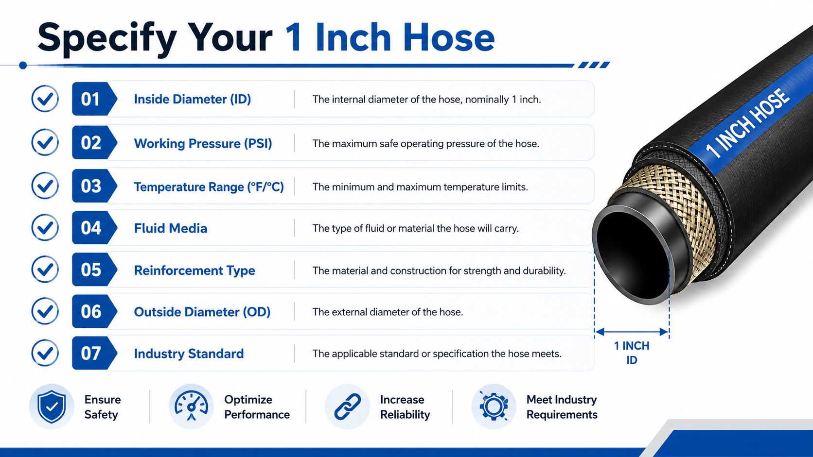
Record these seven points:
- Bore and dash size. State the measured or required bore, such as 25.4 mm and -16, and identify whether the line is pressure, return, suction or another service.
- Working and peak pressure. Include normal pressure, maximum pump pressure and known spikes. A hose's working rating must cover the circuit duty.
- Bend radius and routing space. Provide a drawing, photograph or measurements around brackets, cylinders and moving joints.
- Fluid and temperature. Name the fluid and include the expected fluid and ambient temperature range.
- End connections. Specify BSPP, BSPT, JIC, ORFS, Code 61, Code 62, flange or another connection, including orientation.
- Finished length. Measure between sealing faces and include the bend allowance required by the installed route.
- Cleaning and certification. State cleanliness requirements, pressure-test documentation and any site or industry paperwork.
Standards and assembly evidence
Ask which standard applies, such as BS EN 853, BS EN 856 or BS EN 857, then check the actual product sheet for pressure, bend radius, outside diameter and fitting compatibility. A standard name doesn't give permission to mix components from unrelated systems.
For proof testing, request the documentation required by your quality system, including pressure-test certification where applicable. BS EN 857 product data shows why the same nominal bore can have a different bend characteristic between constructions. The listed 1 inch 1SC example gives 88 bar operating pressure, 352 bar burst pressure and a 230 mm maximum bend radius.
A generic web order often captures bore and length but misses fitting orientation, hose standard, cleanliness and pressure class. A bespoke assembly from MA Hydraulics Ltd can be specified around the application, with the hose cut, cleaned, crimped and proof-tested to the required assembly details rather than selected only as a shelf item.
Copy this into a procurement email:
- Hose bore and dash size
- Working and peak pressure
- Minimum installed bend radius
- Fluid and temperature range
- Hose standard and construction
- End connection type and orientation
- Finished length, test and cleaning requirements
Send a drawing, photographs or the sample hose ends if you're replacing an existing assembly. That evidence lets the supplier verify the connection, routing and construction instead of making assumptions from the 1 inch label.
For a 1 inch hydraulic hose, MA Hydraulics Ltd can help identify the correct bore, pressure class, fittings and finished assembly for mobile or industrial equipment. Visit MA Hydraulics Ltd with your hose details, drawing or sample ends, phone 01724 279508 today, or send us a message for a replacement or bespoke assembly quotation.
