A telehandler arrives with a loader valve that's sticking, the outlet pressure looks wrong, and the regulator gets the blame. A fitter swaps the unit, tests the machine, and finds the fault is still there. Then the filter element comes out. It's black, loaded with swarf and doing little more than restricting the circuit.
That job captures the purpose of a filter pressure regulator. It combines contamination control with downstream pressure control, but it can't compensate indefinitely for poor fluid condition, incorrect sizing or a drain that never works. The right unit protects sensitive components and stabilises operation. The wrong one just becomes another restriction in the line.
What a Filter Pressure Regulator Does
A filter pressure regulator is a combined device with two jobs. The filter removes contamination from line fluid or compressed air, while the regulator reduces inlet pressure and holds the outlet at a controlled setting. In pneumatic service, RS Online's explanation of filter regulators describes the unit as a filter and pressure regulator working together, removing dirt, dust and water while maintaining constant output pressure.
That combination suits equipment requiring both a clean supply and stable pressure. Pneumatic versions are used on factory manifolds, machine control panels, cab air circuits and pilot lines. Hydraulic filtration and pressure control are commonly installed as separate components, although a combined device can protect a compact branch where both functions are needed.
A standalone filter removes contamination but does not set downstream pressure. A standalone regulator controls pressure but provides no meaningful protection against dirt, water or wear debris. Combining them saves space and simplifies a branch circuit. The housing, element, regulating mechanism and pressure rating must still match the application.
Where it earns its place
On mobile machinery, the unit can protect a pilot circuit, air-operated control system or dedicated hydraulic branch. On industrial equipment, it may sit ahead of directional valves, proportional valves, solenoid banks or other components that require a predictable supply.
The UK standards framework separates these functions clearly in compressed-air service. BS ISO 6953-1:2015 covers compressed-air pressure regulators and filter regulators. The British Fluid Power Association library also lists BS ISO 5782-1:2017 for compressed-air filters and BS ISO 16860:2005 for filter differential-pressure devices. These references connect filtration, pressure regulation and monitoring without treating them as interchangeable labels. The BFPA standards library provides the relevant UK standards context.
For hydraulic circuits, specify cleanliness using the system's required ISO 4406 code, then check whether the combined unit can maintain that condition at the required flow. A compact assembly can simplify protection, but its element capacity and pressure drop still determine how well the branch performs.
Practical rule: If a regulator replacement does not cure unstable operation, inspect the element and measure pressure before and after the filter. Contamination is a common cause of apparent control faults, so measure pressure drop across the element before condemning the regulator.
Inside the Unit, Filter, Regulator and How They Interact
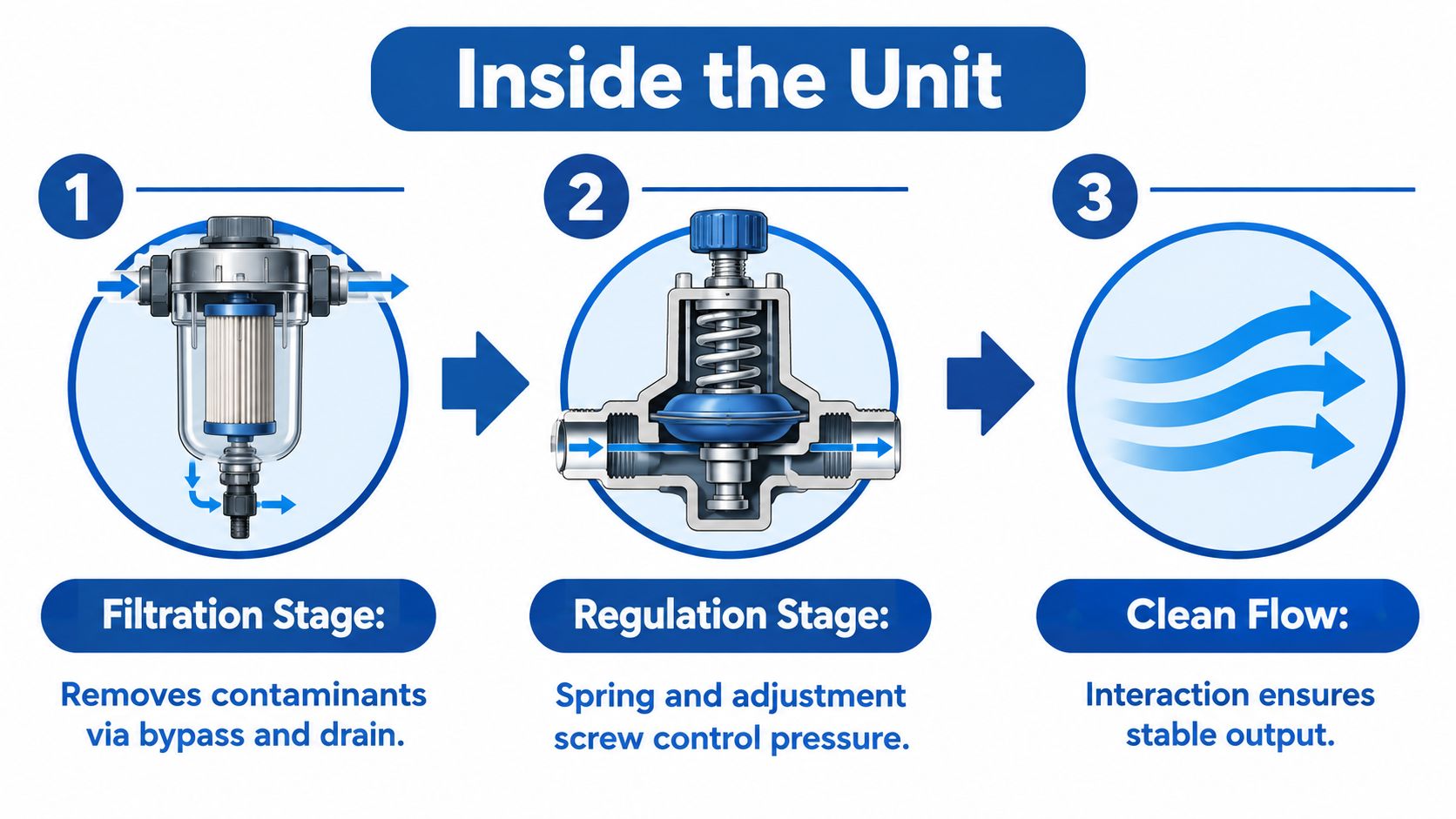
A typical assembly has a filter side and a regulating side in one housing. The filter side contains a bowl, element, water-separation features and usually a manual or automatic drain. The regulator side uses a diaphragm or piston, spring and adjustment mechanism to respond to outlet pressure.
Clean air or fluid enters the inlet and passes through the element. The element holds back solid contamination, while separated water or collected debris moves towards the bowl and drain. The pressure-control section then reacts to downstream demand. If outlet pressure falls below the set point, the valve opens further. If pressure rises, the mechanism restricts the inlet or relieves excess pressure, depending on the design.
What a loaded element does
As the element collects debris, the pressure difference across it increases. The regulator may initially compensate by opening further, so the operator sees a normal outlet setting. That reserve disappears as flow rises. The outlet pressure then droops, actuators become less repeatable and the regulator can appear to be failing when the actual problem is restriction.
An element's bypass, where fitted, opens when differential pressure reaches its designed threshold. That protects against complete blockage, but it can also allow contaminated fluid or air to pass directly downstream. A bypass is a safety feature, not a substitute for service.
Typical pneumatic filter-regulator products illustrate the range engineers need to check. UK catalogue data includes 40-micron filtration, adjustable outlet pressure from 0.5 to 12 bar and flow capacity of 1,500 l/min for a widely sold compact unit, as shown in the RS Online filter-regulator range. Hydraulic filter housings require a separate pressure and flow assessment, including the housing's differential-pressure behaviour. For a broader view of hydraulic installation options, see the hydraulic filter housing range.
The practical interaction is simple. The filter protects the regulator and downstream equipment, while the regulator keeps the cleaned supply usable. Neither half can rescue a unit that's too small, fitted backwards or left in service after its pressure drop has become excessive.
Pneumatic vs Hydraulic Use
Pneumatic and hydraulic filter pressure regulators may look similar in a catalogue, but they operate in different engineering environments. Pneumatic filter regulators are generally used in air-preparation assemblies, with catalogue examples covering outlet ranges such as 0.5 to 8.5 bar, and filtration options including 25 μm and 5 μm. A UK SMC range also lists filter-regulator models with up to 17,500 l/min flow and stated ISO 8573-1:2010 compliance, so the data sheet matters more than the product name.
Hydraulic circuits place greater emphasis on oil cleanliness, pressure pulsation, viscosity and component protection. UK guidance identifies pressure-filter applications from 100 bar to 420 bar, with lower-pressure designs available up to 34 bar, as described in this UK hydraulic filter selection guide. ISO 4406 coding uses particle bands at 4 µm(c), 6 µm(c) and 14 µm(c), so a hydraulic specification must state the required cleanliness code rather than merely saying "fine filtration".
| Parameter | Pneumatic | Hydraulic |
|---|---|---|
| Main medium | Compressed air | Hydraulic oil |
| Typical purpose | Air cleaning, water separation and regulated supply | Oil cleanliness and controlled branch pressure |
| Common reference | BS ISO 6953-1:2015 and ISO 8573-1:2010 | ISO 4406 cleanliness coding |
| Typical filtration language | Micron rating and air-quality class | Cleanliness code, element rating and beta performance |
| Installation context | FRL assembly, cab circuit, pilot air or manifold | Pressure, return or dedicated branch circuit |
| Main risk if mismatched | Pressure droop, water carry-over or air leakage | Heat, restriction, component wear or uncontrolled pressure |
Don't fit a pneumatic FRL unit into a hydraulic line because the thread and nominal pressure appear convenient. The bowl materials, seals, element construction, drain arrangement and maximum pressure may be unsuitable. Likewise, a hydraulic filter assembly won't automatically provide the water separation and pressure-control behaviour expected in a compressed-air circuit.
For pneumatic maintenance, air quality is only part of the job. Good pipework practice and attention to preventing air brake leaks help avoid losing the pressure that the regulator is trying to maintain. Engineers working across both disciplines can use MA Hydraulics' hydraulics and pneumatics range to keep the component choice tied to the actual medium and circuit duty.
How to Specify One for Your System
A filter pressure regulator on a tractor pilot circuit, factory air panel or mobile hydraulic branch must be specified for the medium, duty and downstream components. Port size is only one part of the selection. Start by recording the required flow, pressure range, cleanliness target and material compatibility.
1. What flow must it pass?
For compressed air, state the required flow in litres per minute, or normal litres per minute if that is how the manufacturer publishes its figures. A compact UK pneumatic unit may be rated at 1,500 l/min, while a modular SMC family lists models up to 17,500 l/min, according to the SMC UK product data. These ratings cannot be compared directly. Check the flow at the intended inlet and outlet pressures rather than relying on the headline maximum.
Hydraulic selection needs flow and pressure considered together. A filter that passes the required volume at low viscosity can impose excessive restriction during a cold start, particularly on mobile plant. Use the manufacturer's pressure-drop curve and allow capacity for contamination loading as the element fills.
2. What are the pressure limits?
Record maximum inlet pressure, normal operating pressure and the regulated pressure required by the equipment. Pneumatic catalogue ranges may include 0.5 to 12 bar. Hydraulic pressure filters can cover much higher duties, including 100 to 420 bar in Parker's UK hydraulic filter guidance. Rate the complete assembly for the circuit. The body, bowl, seals and drain must match the duty, not just the regulator spring.
3. How clean must the medium be?
For hydraulic oil, set the target with an ISO 4406 cleanliness code. The MA Hydraulics filter selection guide gives 19/17/14 as a commonly used baseline, with cleaner systems targeting around 16/14/11, depending on the application. The UK ISO 4406 filter selection guidance also relates component duty to targets, including 20/18/15 for gear pumps and motors with a 20 µm absolute rating, 19/17/14 for some fixed-displacement pumps and actuators with 10 µm filtration, and 16/14/11 for servo valves and hydrostatic drives with 3 µm filtration.
For pneumatic equipment, specify the required air-quality class and water-separation performance. A particulate element alone may not suit compressor-fed equipment where condensate reaches the bowl. BS ISO 6953-1 and BS ISO 5782 help frame pneumatic regulator and valve selection, while ISO 4406 applies to hydraulic oil rather than compressed air.
4. Are the materials compatible?
Check the hydraulic oil, additives, operating temperature and seal material. For pneumatic service, check the bowl, element and drain against moisture, cleaning chemicals and outdoor exposure. Mobile equipment also needs protection from vibration and contamination during servicing.
| Selection Question | Pneumatic Range | Hydraulic Range | Notes |
|---|---|---|---|
| Required flow | From compact machine circuits to high-flow modular assemblies | Matched to pump, branch or return flow | Use the manufacturer’s flow and pressure-drop curves |
| Working pressure | Common catalogue examples include 0.5 to 12 bar | Guidance covers applications from lower pressure to 420 bar | Confirm maximum inlet pressure and regulated outlet pressure |
| Cleanliness target | Air filtration and ISO 8573-1 quality requirements | ISO 4406, such as 19/17/14 or cleaner targets | Match filtration to the most sensitive downstream component |
| Fluid compatibility | Compressed air, water separation and drain suitability | Oil, additives, seals, bowl and element media | Compatibility failures often appear as swelling, cracking or leaks |
Common errors include choosing by port size alone, overlooking cold-start viscosity, fitting filtration that is too coarse for a servo valve, or specifying a drain that cannot be serviced in a humid compressor room. Confirm the actual medium and circuit duty before ordering.
Installation Best Practice on Hydraulic and Pneumatic Circuits
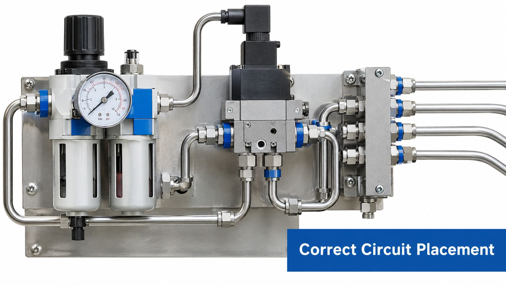
Position the unit where it can protect the equipment that matters. On a hydraulic branch, that generally means upstream of directional control valves, proportional spools or pilot components. On a pneumatic panel, place it downstream of the receiver and dryer so the filter pressure regulator receives air that has already had bulk moisture removed.
Mount the bowl vertically, with the drain at the lowest point. A sideways bowl can leave water and debris trapped where the drain can't remove them. In a mobile application, protect the assembly from direct impact, excessive vibration and heat from exhaust or hydraulic lines.
Details that prevent service problems
Fit an isolation valve or bypass arrangement where the circuit allows it. The aim is to change an element without depressurising an entire machine or plant section. Don't create a bypass that lets unfiltered flow reach sensitive valves during normal operation, and make sure the service procedure identifies which valve must be closed first.
Put the pressure gauge on the regulated outlet, not merely on the inlet. The inlet gauge tells you what the supply provides. The outlet gauge tells you whether the regulator is maintaining the pressure the downstream equipment receives.
Use the manufacturer's torque figure for ports and fittings. Guesswork can split a casting, distort a seal or leave a connection loose enough to leak under vibration. Leave enough clearance to remove the bowl and element, label regulated and unregulated ports, and confirm the flow arrow before commissioning.
Maintenance, Service Intervals and Troubleshooting
Fitting a larger filter pressure regulator isn't always the answer. A larger body may reduce initial restriction, but it won't fix water entering through a failed drain, contamination coming from upstream or a regulator diaphragm that has become damaged. Service life depends on the dirt load, flow profile, temperature, fluid condition and how pressure drop changes over time.
For compressed air, make the bowl drain part of the routine. A weekly visual check and drain inspection catches water accumulation before it reaches valves and actuators. Manual drains need someone to operate them. Automatic drains need someone to confirm that they aren't blocked, stuck open or passing compressed air.
Hydraulic service needs measurement rather than guesswork. Trend pressure drop across the element, inspect removed media and use fluid sampling to track cleanliness. The UK guidance's ISO 4406 examples show why a visual inspection alone isn't enough. Oil can look acceptable while particle counts are already unsuitable for sensitive components.
A practical fault-finding sequence
-
Creeping outlet pressure: Check whether the adjustment lock has moved, the diaphragm is damaged or contamination is holding the regulating seat open. Verify inlet pressure before condemning the regulator.
-
Outlet pressure droops under flow: Measure pressure before and after the filter. A loaded element, undersized housing or excessive viscosity can create the restriction.
-
Water in a pneumatic bowl: Inspect the receiver, dryer and drain. A filter pressure regulator can separate water that reaches it, but it can't replace a failed upstream dryer.
-
Diaphragm chatter: Look for unstable inlet pressure, pulsating demand, contamination at the regulating seat or a regulator operating outside its flow range.
-
Repeated element blockage: Find the contamination source. On mobile plant, that may be poor tank cleanliness, damaged breathers, hose degradation or work taking place in a dusty environment.
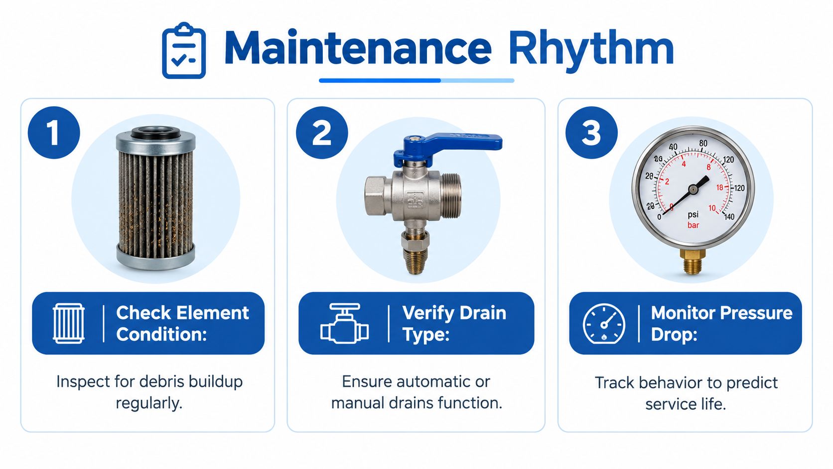
Replace elements according to measured condition and the manufacturer's differential-pressure limit, not an arbitrary calendar alone. The hydraulic filter kit range can help identify the correct replacement format, but the element rating still has to match the circuit's cleanliness requirement.
A filter that looks clean can still be the wrong filter. Confirm the element specification, differential pressure and downstream cleanliness target before refitting it.
Application Examples Across Mobile and Industrial Equipment
The same basic device behaves differently depending on where it sits and what it protects. A tractor, fork truck and factory manifold each impose different demands on flow, pressure, contamination and service access.
A tractor auxiliary circuit feeding a tipping trailer valve needs attention to hydraulic flow and pressure, not just the physical connection. If a 10 µm element loads with debris, the remote function may show pressure instability or slow response. The sensible response is to check the element condition, measure pressure drop and investigate where the contamination entered rather than fitting a higher-pressure regulator without changing the filtration strategy.
A fork truck mast circuit is more sensitive to repeatability around the lift function and proportional control. Where the circuit target is ISO 4406 19/17/14, filtration must be selected to support that cleanliness level, with the housing and element capable of handling the circuit pressure and flow. A regulator that holds the branch pressure but passes contaminated oil hasn't protected the proportional valve.
In a factory pneumatic manifold, a coalescing filter regulator may feed solenoid banks at a stable setting. A 5 µm element can be appropriate where the air-quality requirement calls for finer particulate control, but the drain and bowl capacity still determine whether the arrangement works on a humid shop floor. An automatic drain may reduce operator intervention, while a manual drain can be perfectly serviceable where inspection is frequent and access is easy.
| Application | Typical duty | Filter rating | Regulated pressure | Cleanliness target |
|---|---|---|---|---|
| Tractor auxiliary branch | Mobile hydraulic flow to a trailer or implement valve | Selected for the valve and circuit contamination target | Set to the branch requirement | Defined through ISO 4406 |
| Fork truck mast circuit | Controlled hydraulic supply for lift and proportional functions | Selected to protect sensitive control components | Matched to the lift circuit | Around ISO 4406 19/17/14 where specified |
| Factory pneumatic manifold | Compressed air to solenoid banks | Fine particulate or coalescing filtration as required | Stable machine supply pressure | ISO 8573-1 requirement |
These examples share one lesson. The combined unit must be specified around the downstream component and actual duty cycle, not chosen because its inlet and outlet threads happen to match the existing pipework.
Quick Reference Checklist and Next Steps
Keep the selection sheet beside the machine paperwork. Before ordering, write down the medium, flow, pressure, mounting position, element rating and service access. That record prevents a replacement from being matched only by thread size.
Before ordering
- Size flow: Allow a design margin of 1.2 to 1.5 times actual demand, as required by the application plan, then check the manufacturer's pressure-drop data at the actual operating conditions.
- Confirm pressure: Record maximum inlet pressure, normal operating pressure and the required regulated outlet. Don't use a pneumatic unit in a hydraulic circuit or assume a hydraulic housing suits compressed air.
- Set cleanliness: Define the hydraulic target using ISO 4406 and select filtration for the most sensitive downstream component. Check the stated element performance rather than relying on a nominal micron label.
- Check compatibility: Confirm seals, bowl material, element media, oil or air chemistry, temperature and outdoor exposure.
- Verify the drain: Match manual or automatic drainage to the mounting orientation and the maintenance access available to the operator.
- Plan the installation: Confirm port direction, gauge location, isolation arrangements and clearance for element removal.
- Record the baseline: Measure and record clean-element pressure drop after commissioning. Future readings become useful only when you have a known starting point.
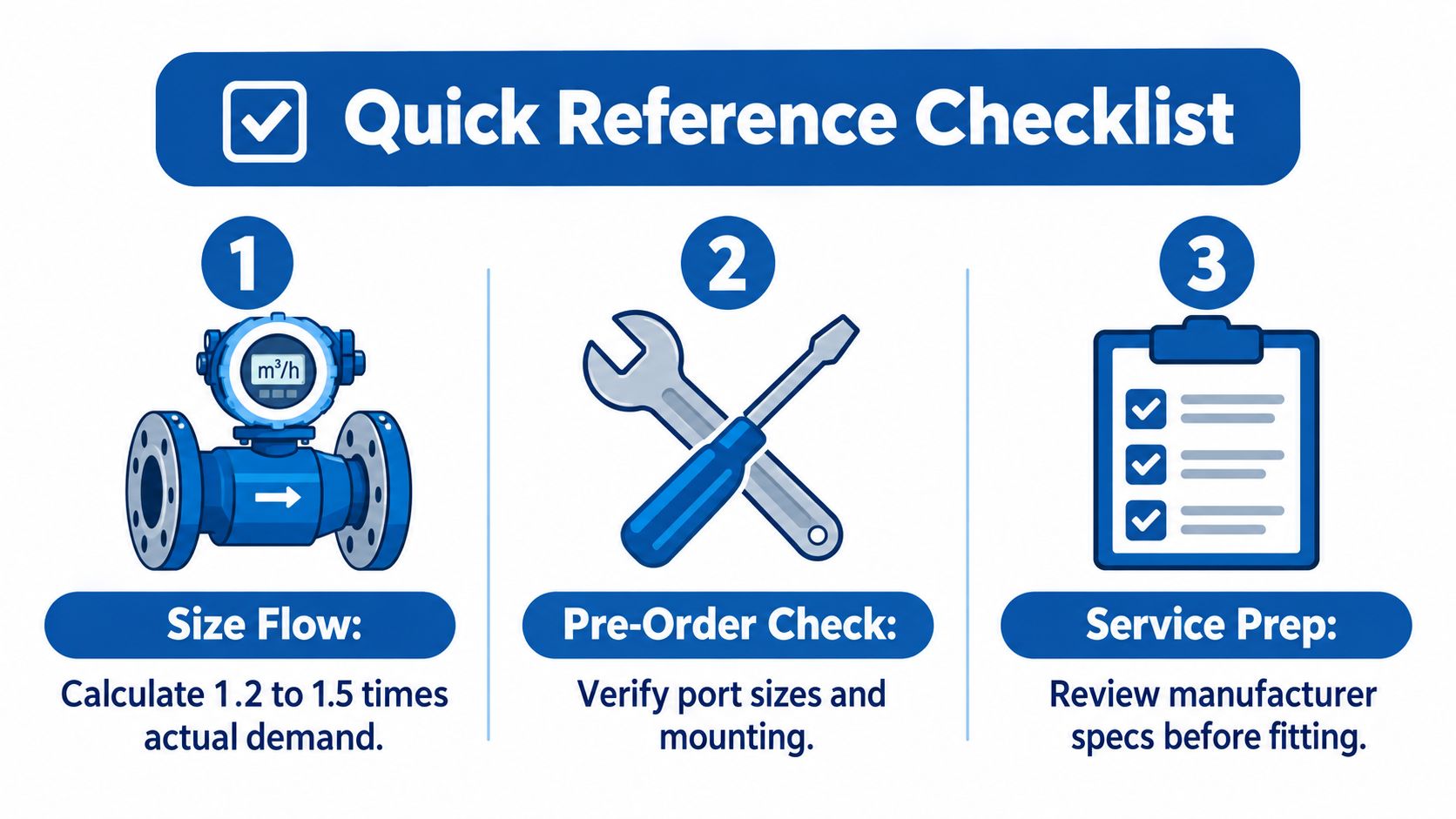
For maintenance, use a weekly visual check on bowls, drains, leaks and gauge readings. Inspect elements at the planned service review, and use a heavier annual replacement routine where the equipment works in dust, moisture, vibration or high contamination loads. Always follow the specific manufacturer's service limits when they differ from a general workshop schedule.
When replacing a Bosch Rexroth, Festo or Parker unit, record the original model, ports, element rating, pressure range and flow requirement before cross-referencing. MA Hydraulics Ltd can support hydraulic filter selection, spare-element identification and component cross-reference work for mobile and industrial systems.
MA Hydraulics Ltd supplies hydraulic filters, housings, elements and related components, with technical support for matching pressure, flow, filtration and circuit placement. Visit MA Hydraulics Ltd for specification help and replacement support, phone 01724 279508 today, or send us a message with your existing component details.