
External gear pumps accounted for around 40% of the approximately £450 million UK hydraulic components market in 2023, making them the most commonly seen pump in UK mobile and industrial work. For engineers and procurement teams, that market position reflects a practical choice: fixed-displacement performance, straightforward servicing and fast replacement remain valuable across British plant and machinery.
That popularity doesn't mean every external gear pump is interchangeable. Pressure class, displacement, rotational speed, viscosity, inlet conditions, mounting interface, leakage control and the intended duty cycle all affect whether a pump will deliver reliable service. Energy efficiency and regulatory compliance now add further selection pressure, particularly for OEMs supplying automated manufacturing, mobile plant and industrial fluid-handling equipment.
Why External Gear Pumps Dominate UK Hydraulics
The scale of the UK market explains why these pumps appear so frequently in maintenance stores, mobile machinery and factory hydraulic systems. The wider UK hydraulic components market was valued at approximately £450 million in 2023, while gear pumps accounted for around 40% of that market, according to UK gear pump market information from MA Hydraulics. That gives external gear pumps a substantial role in the infrastructure engineers already work with.
Walk into a manufacturing plant and you may find one on a lubrication circuit, an oil-transfer system or a compact power unit. Visit an agricultural or materials-handling workshop and the same basic architecture may appear as a replacement pump on mobile equipment. Engineers encounter external gear pumps repeatedly because they suit applications where predictable fixed displacement matters more than variable-flow sophistication.
Why workshops keep choosing them
An external gear pump moves a consistent volume for each revolution. That makes the relationship between shaft speed and delivered flow easy to understand during initial sizing and fault diagnosis. The design also avoids some of the complexity associated with more elaborate pump architectures, which helps maintenance teams identify a replacement and return equipment to service without an extended redesign.
The practical advantages are straightforward:
- Fixed-displacement operation: Flow follows pump displacement and drive speed, making the unit suitable for uncomplicated hydraulic circuits.
- Serviceable construction: The casing, gears, bearings and seals provide familiar inspection points for repair teams.
- Replacement availability: Standard ranges and common mounting arrangements support faster sourcing than highly specialised imported assemblies.
- Broad use: UK sources describe external gear pumps as the most commonly seen pump in mobile and industrial work, including lubrication and oil-transfer duties.
A procurement manager usually values the same features for a different reason. A pump that can be cross-referenced accurately, sourced through an established UK supply chain and fitted without extensive changes reduces the risk of prolonged downtime. The cheapest purchase price isn't necessarily the lowest-cost decision if an incorrect interface, shaft or displacement creates installation delays.
Practical rule: Treat a gear pump as part of a complete hydraulic duty, not as an isolated catalogue item. The circuit determines whether its apparent simplicity becomes a benefit or a limitation.
The UK perspective also matters for new equipment. British manufacturers face pressure to reduce energy loss, support automation and demonstrate regulatory readiness. External gear pumps can meet those needs when engineers specify the operating envelope carefully, control leakage and select materials and seals for the actual fluid and environment.
How External Gear Pumps Actually Work
An external gear pump is a positive displacement pump. It moves a fixed quantity of fluid per revolution, while pressure comes from resistance in the downstream circuit, not from the pump independently “making pressure”, as explained in MA Hydraulics' guide to how a gear pump works.
That distinction matters. If a relief valve is closed or an actuator encounters resistance, the pump continues trying to displace fluid. The system pressure rises because the flow has met resistance. A positive displacement pump therefore needs suitable pressure-limiting protection and correctly specified components.
The movement inside the casing
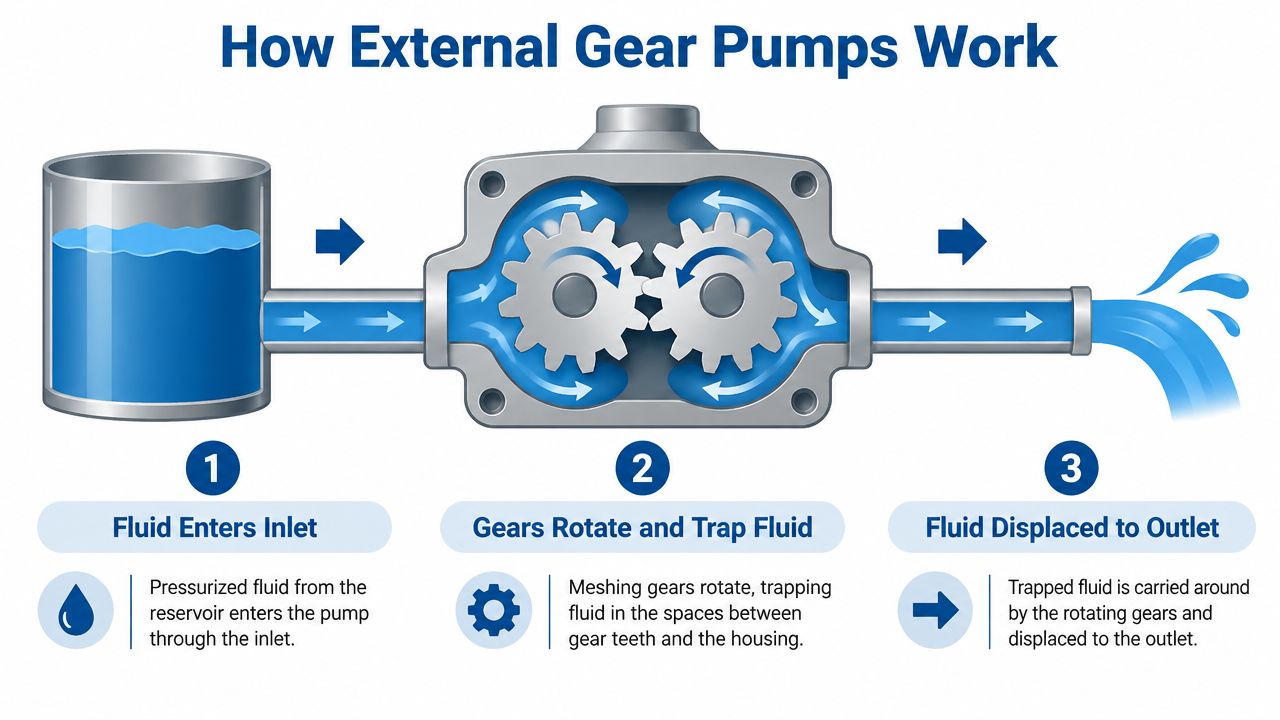
A standard design contains two equal external gears inside a closely fitted housing. The drive gear turns the second gear, and the teeth create changing cavities as they rotate.
- Inlet cavity opens: On the inlet side, the gear teeth separate. The cavity volume increases, creating the conditions for oil to enter the pump.
- Fluid becomes trapped: Oil occupies pockets between the gear teeth and the housing bore. The pump carries those pockets around the outside of the gears.
- Outlet cavity closes: At the outlet, the gear teeth mesh again. The reducing cavity volume forces the oil into the discharge port.
The fluid doesn't pass directly through the point where the gears mesh. Instead, it travels around the outer circumference in pockets formed by the teeth and casing. This arrangement is the reason the pump delivers a smooth, pulse-free flow that remains proportional to gear speed, as described in this technical explanation of external gear pump principles.
What this means for specification
A faster shaft generally produces more flow, provided the pump remains within its rated speed, inlet and pressure limits. Increasing resistance raises pressure, but it doesn't create additional displacement. If the circuit demands more flow, the engineer must assess displacement and drive speed rather than just selecting a pump with a higher pressure rating.
The close clearances also explain why contamination, poor lubrication and unsuitable viscosity can cause trouble. The pump relies on controlled internal leakage and accurate gear-to-housing relationships. Excessive wear increases slip, reduces delivered flow and can make the pump appear undersized even when its nominal displacement is correct.
Understanding that sequence gives a useful diagnostic foundation. Low flow might indicate insufficient speed, internal wear, inlet restriction or excessive fluid viscosity. A pressure problem may originate downstream rather than in the pump. Good selection starts by separating those possibilities instead of assuming every hydraulic fault is a pump fault.
Types and Groups of External Gear Pumps
Start with the required direction of rotation. A unidirectional pump suits a circuit where the drive and flow direction stay fixed. A reversible pump is required when the application must swap inlet and outlet functions or run the pump in either direction.
The distinction goes beyond port markings. Reversible designs may use different sealing, bearing and port arrangements, so a unidirectional unit is not an automatic substitute for a bidirectional pump. Confirm shaft rotation, drive arrangement and pressure behaviour against the machine duty before approving a catalogue match.
How Group 0 through Group 3 helps
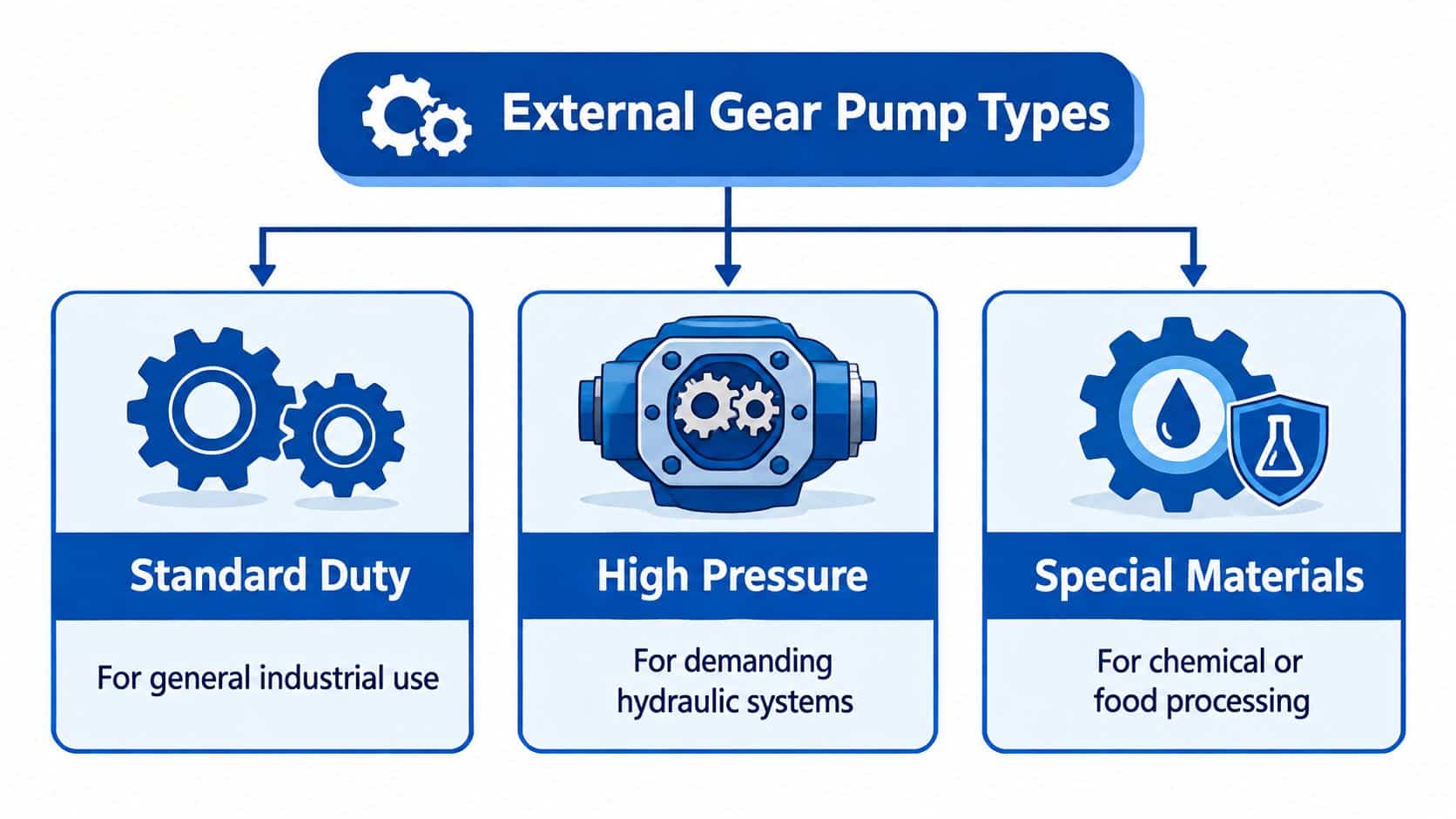
UK suppliers commonly use Group 0, Group 1, Group 2 and Group 3 to organise external gear pumps by physical size, displacement range and mounting arrangement. The number identifies a pump family and its mechanical envelope. It does not, by itself, indicate application quality, pressure capability or suitability for a particular machine.
Check the actual specification alongside the group:
| Selection point | Why it matters |
|---|---|
| Displacement | Sets the volume moved per revolution and the flow available at the drive speed. |
| Frame size | Defines the physical envelope and available installation space. |
| Shaft dimensions | Must match the coupling, gearbox, PTO or motor drive. |
| Flange and port arrangement | Determines whether the pump can mount and connect without modification. |
| Pressure and speed rating | Shows whether the unit can handle the real duty rather than only the nominal machine requirement. |
An agricultural implement may favour compact packaging, dependable replacement and compatibility with a mobile power source. A factory hydraulic station may give greater weight to noise, continuous operation, leakage control, energy use and automation interfaces. The same broad pump group can serve both environments, but the acceptance criteria are different.
The external gear pump market outlook projects industry growth at 3.6% CAGR from 2025 to 2035, linking demand with precision machining, aerospace, food processing and sustainability pressures. This forecast does not replace application engineering. For UK OEMs and MRO teams, it reinforces the need to connect group selection with the machine's duty, service conditions and expected operating life.
Energy and compliance belong in the same conversation
Energy performance depends on internal leakage, operating pressure, shaft speed, fluid condition and the time spent under load. Review those factors together, particularly where UK energy-reduction programmes target mobile plant or factory hydraulics. A pump that meets peak pressure but spends much of its service life throttling or leaking may impose avoidable electrical or fuel consumption.
Compliance requires a documented selection trail. Record the chosen configuration, material compatibility, seals, mounting arrangement and supplier information, then check the requirements applying to the complete machine and its intended market.
UKCA readiness does not come from selecting a group number. It depends on the machinery conformity process, technical file, risk assessment and applicable requirements. Pump selection supports that work when the engineer can show why the pressure class, materials, seals and mounting arrangement match the declared duty. That evidence also helps procurement teams assess replacements without treating physical fit as proof of technical equivalence.
Performance Specifications That Drive Selection
A catalogue figure becomes useful only when it answers a real operating question. Consider UK distributor-documented Bosch Rexroth AZP external gear pumps. The listed range reaches up to 280 bar intermittent pressure, while related SILENCE variants are specified at up to 250 bar continuous operating pressure. The same Bosch Rexroth AZP product information shows maximum rotational speeds from 2,500 to 4,000 rpm, displacements from 4 to 22.5 cm³/rev and mineral-oil viscosity compatibility from 10 to 300 mm²/s.
Those values aren't a promise that every model can run at every limit simultaneously. A larger displacement variant may have a different speed and pressure envelope from a smaller one. The engineer must match the specific part number to the actual combination of flow, pressure, speed, viscosity, temperature and duty cycle.
Read the ratings as a matrix
Start with required flow. Relate the target flow to displacement and shaft speed, then check whether the drive can provide that speed without imposing excessive mechanical or thermal load. Next, compare working pressure with the pump's continuous and intermittent ratings, keeping normal operating conditions separate from short-duration peaks.
The key checks are:
- Pressure class: Distinguish continuous operation from intermittent peaks. Running close to a limit for long periods calls for careful system review.
- Speed envelope: Confirm the actual shaft speed, not only the motor's nominal rating. Coupling and gearbox ratios can change the pump speed substantially.
- Displacement: Select enough volume for the required flow, but don't use excess displacement if it forces the drive beyond its practical load.
- Viscosity: Compare the fluid's cold-start and operating viscosity with the manufacturer's permitted range.
- Inlet conditions: A restricted or undersized inlet can starve the pump even when the pressure and displacement calculations look correct.
- Thermal loading: High pressure and sustained operation convert input power into heat. Check how the system removes that heat.
The pressure capability on larger displacement variants rises faster than their speed capability in the cited AZP data. For an OEM, that means operation near the upper pressure limit deserves tighter control of oil cleanliness, inlet conditions and temperature. Those controls help preserve volumetric efficiency and bearing life.
Efficiency includes noise and mechanical loading
Independent UK technical information reports that modern external gear pumps can achieve overall efficiencies normally above 90%, while low-noise variants reduce sound emission by about 15 dBA and up to 20 dBA compared with standard gear pumps, according to UK gear pump technical guidance. The same source groups external gear pumps across displacements from 0.19 to 200.3 cm³/rev and continuous working pressures up to 280 bar.
Lower noise isn't only a comfort benefit. Improved meshing control and pulse attenuation can reduce pressure ripple, structural excitation and fatigue loading in compact mobile and industrial circuits. Engineers assessing a replacement should therefore consider acoustic behaviour alongside efficiency, especially where the pump sits close to operators or sensitive equipment.
For a practical method of relating flow, pressure and efficiency to duty, use guidance on reading pump curves. The right choice is the one whose complete operating envelope fits the machine, not the one with the most impressive single rating.
Common Failure Modes and Practical Maintenance
Most external gear pump failures begin with operating conditions that the pump has been asked to tolerate repeatedly. Contaminated oil, restricted inlet flow, unsuitable viscosity, excessive pressure and neglected seals can all increase wear before the operator notices a clear fault.
The first diagnostic step is to record the symptom under defined conditions. Note flow behaviour, pressure, noise, temperature, visible leakage and drive load. Changing several components at once can hide the original cause and leave the replacement exposed to the same problem.
Match symptoms to likely causes
| Symptom | Practical inspection |
|---|---|
| Reduced flow | Check shaft speed, internal leakage, oil viscosity and contamination-related wear. |
| Pressure loss | Confirm downstream demand, relief-valve behaviour, seal condition and gear-to-housing wear. |
| Abnormal noise | Inspect the inlet path, fluid condition, coupling alignment and bearing condition. |
| External leakage | Examine shaft seals, port seals, casing joints and mounting faces. |
| Rising temperature | Check pressure duty, relief-valve bypassing, viscosity and cooling capacity. |
Contamination deserves particular attention because abrasive particles can damage the close clearances that support efficient displacement. Inspect filters and sampling points, look for scoring on removed components and correct the source of contamination rather than replacing the pump alone.
Cavitation is often confused with ordinary gear noise. A restrictive inlet, poor hose routing, blocked suction filtration or oil that is too viscous during cold starting can deprive the pump of fluid. The pump then draws vapour and suffers local damage, which may appear as pitting, harsh noise or unstable delivery.
A replacement pump won't solve an inlet problem. It may only give the same fault a new set of components to damage.
Repair or exchange
Bearing or seal replacement can make sense when the gears and housing remain within the manufacturer's service limits. If the casing is scored, the gear clearances are excessive or the pump has suffered prolonged contamination, a complete exchange may be more economical than rebuilding individual parts.
Before refitting, flush or clean the circuit as appropriate, renew contaminated fluid and verify the inlet path. Set the relief protection correctly, align the drive and confirm rotation before applying full load. The operating mechanism described in this external gear pump principles document depends on close internal relationships, so installation quality directly affects service life.
Installation Considerations and Cross-Reference Guidance
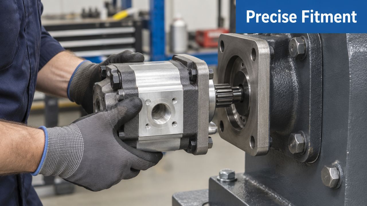
A replacement pump must fit the machine's interface and duty, not merely resemble the original. UK listings show common external gear pump standards such as ISO DIN5462 4-bolt flanges and UNi 3-bolt flanges, with displacement options including 25, 40, 43, 51, 60, 90 and 110 cc, as shown in UK external gear pump listings.
Record the following before requesting a cross-reference:
- Flange standard: Check the bolt pattern, pilot dimensions and orientation.
- Ports: Match size, thread or flange type, and inlet and outlet positions.
- Shaft: Confirm diameter, key, spline, length and required rotation.
- Displacement: Verify cc per revolution rather than relying on appearance or group number.
- Pressure duty: Compare continuous and intermittent requirements with the proposed pump's rating.
- Seals and fluid: Confirm compatibility with mineral oil or the specified hydraulic fluid.
- Envelope: Measure space around the pump, coupling and hoses.
A familiar group number does not guarantee interchangeability. Shaft geometry, flange dimensions and port orientation can differ within the same broad pump family. Displacement also needs careful review. If the original value is unavailable, changing pump size may require a different drive speed, control setting or mounting arrangement.
Rotation deserves a separate check. A pump with matching displacement and flange can still be unsuitable if its inlet and outlet arrangement conflicts with the drive direction. Use the manufacturer's drawing or datasheet, and do not infer rotation from port positions alone. This check supports safer commissioning and helps prevent an avoidable compliance issue in a UK machine file.
Follow the relevant hydraulic installation guidelines and record the final configuration, including the pump code, displacement, rotation and interface dimensions. A clear record gives OEM and MRO teams a reliable basis for future ordering.
The following video provides a visual review of installation and alignment. Check that its frame displays correctly in the page layout, particularly on mobile screens.
During controlled commissioning, prime the pump according to the manufacturer's instructions, verify rotation and inspect for leaks. Listen for inlet starvation, monitor temperature and confirm that the circuit reaches its expected pressure without unnecessary relief-valve bypassing. These checks can expose poor sizing or installation before wasted energy and repeat failures become routine.
Making the Right External Gear Pump Decision
A sound specification combines direction, group, displacement, pressure, speed, viscosity, mounting and maintenance conditions. Start by defining the circuit's real duty, then select the pump family that fits the required flow and drive arrangement. Finally, verify efficiency, leakage control, materials, installation requirements and the evidence needed for the machine's compliance file.
The UK push towards energy efficiency, automation and regulatory reliability means a like-for-like replacement isn't always the best long-term choice. A correctly matched external gear pump can reduce avoidable losses and service interruptions, but only when the surrounding circuit supports its operating envelope.
MA Hydraulics Ltd can help OEMs, mobile machinery operators, MRO teams and repair companies with gear pump selection, cross-references, bespoke power packs and hard-to-find hydraulic components. Phone 01724 279508 today for application support, or send a message through the contact page.
For external gear pump selection, replacement matching or a bespoke hydraulic power solution, contact MA Hydraulics Ltd. Call 01724 279508 today, or send the team your pump details and application requirements through the contact form so the correct interface, displacement and duty rating can be checked before you order.
