
The pressure figure stamped on a high-pressure ball valve doesn't prove it's right for your circuit. A pump, valve, manifold, hose and fittings work as one pressure boundary. A valve may match the pump's stated pressure and still be unsuitable if switching creates a pressure spike, temperature affects its rating, or another component has a lower limit.
Choose by the conditions at the valve's location and the demands of the complete installation, not by the headline rating alone. That means checking what the manufacturer's pressure figure represents, which product and workplace requirements apply, and whether the valve can be installed, operated and inspected safely.
Why Pressure Rating Alone Does Not Settle the Choice
A catalogue rating is a starting point, not a system approval. A hydraulic circuit can experience pressure peaks during pump start-up or shutdown, actuator switching, or when fluid is trapped and then heated. A valve that appears suitable under steady conditions may face different loads in service. Maximum pressure values may apply only under non-shock conditions, so the expected transient envelope matters as much as the normal operating figure. UK ball-valve installation guidance distinguishes those conditions and warns that hydraulic shock needs separate consideration.
The weakest component sets a practical limit. Check the valve alongside the manifold, hose, tube, fittings and connections. If one fitting has a lower permissible pressure than the valve, choosing a higher-rated valve won't strengthen the assembly. Temperature and fluid compatibility matter too: a pressure figure isn't meaningful in isolation from the conditions under which the manufacturer says it applies.
Practical rule: Specify the valve for the real duty at its location, then check that every connected pressure-containing component can withstand the same operating envelope.
Three questions help keep the decision grounded. What does the manufacturer's stated pressure limit mean for this particular valve and its position in the circuit? Which conformity, workplace and examination requirements apply to the equipment and installation? And can the valve be fitted, isolated and inspected without creating avoidable risk?
Those questions also help separate selection from installation. A valve may suit the design on paper but become difficult to maintain if it's buried behind other equipment or exposed to pipe strain. Conversely, an accessible valve with clear identification and traceable documentation is easier to assess and manage through its service life. Treat the valve as one element of pressure-system integrity, not as a standalone part number.
What Makes a Ball Valve High Pressure
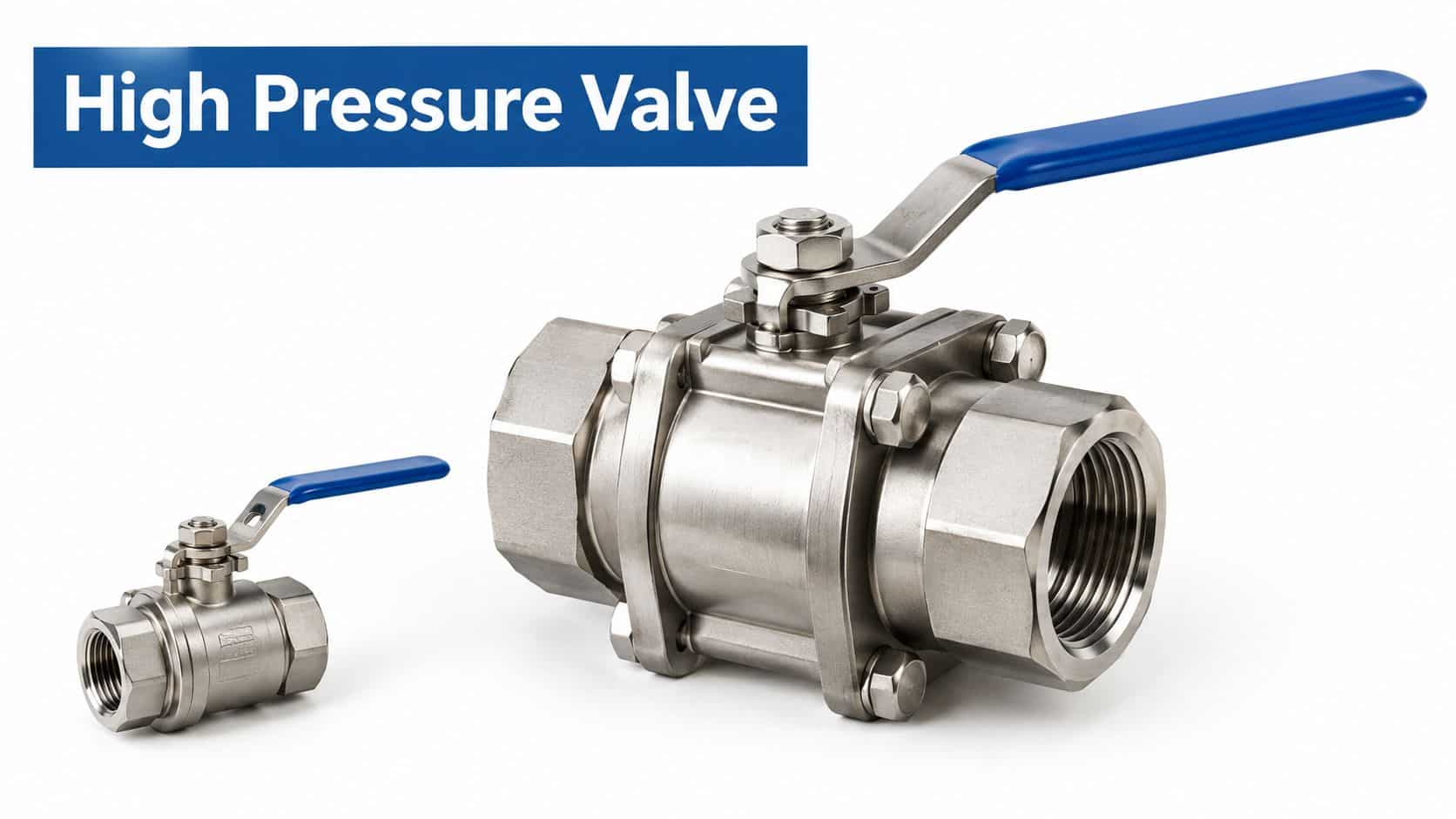
A ball valve controls flow by rotating a drilled ball inside its body. Turn the handle or actuator, and the bore lines up with the pipe to allow flow, or turns across it to close the passage. In high-pressure service, the ball is only one part of the pressure boundary. Body strength, stem retention and sealing, seats, end connections and assembly quality all affect whether the complete valve can contain the fluid under its intended conditions.
A useful mental model is a small pressure vessel with a controlled opening. The body holds the fluid, while the ball, seats, stem seal and connections each provide potential leakage paths. The manufacturer's technical information should show the pressure and temperature limits for the particular design and intended service. Don't assume that a rating printed on a component tells you how the valve behaves with every medium or at every temperature.
Understand the pressure figure
A nominal pressure class such as PN25 is useful shorthand, but it isn't a substitute for the manufacturer's documented limit and conditions. UK legislation defines maximum allowable pressure, or PS, as the maximum pressure for which equipment is designed, specified at a defined location. That location may be a connection for a protective device, the top of the equipment, or another point identified by the manufacturer. For valve selection, compare the documented PS and operating limits with pressure at the valve's actual location, including possible peaks. The legal definition of PS makes clear why a rating shouldn't be treated as a generic limit for the entire circuit.
Bore size affects flow as well as fit. A full-bore valve has an opening close to the internal diameter of the connecting line, reducing restriction through the valve. A reduced-bore design has a smaller opening and can impose more restriction. Choose based on the circuit's flow requirements and the valve's intended function, rather than assuming one design is always preferable.
See the video below for a visual introduction to valve operation. Check that the embedded frame displays at the correct proportions on the page.
Flow control requirements vary by application. For readers comparing related equipment used in gas service, this overview of mobile natural gas flow controls provides useful context, though a hydraulic valve still needs to be selected against its own medium, pressure and installation requirements.
Body Designs, Materials and Seat Options Compared
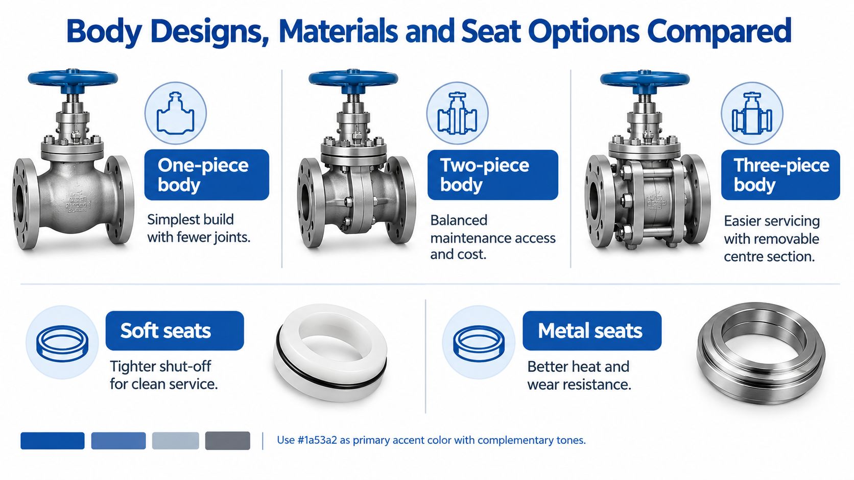
Body construction determines how the valve is assembled and how much access maintenance may require. A one-piece body has fewer joints, but servicing may be more restricted. A two-piece design offers a balance between construction and access. A three-piece body has a removable centre section, which can make servicing easier where the installation allows it. The practical choice depends on how the valve will be fitted and whether it can be removed or maintained safely in place.
Match materials to the fluid and surroundings
Carbon steel, stainless steel and brass each serve different duties. Carbon steel is used where high strength is needed; stainless steel can be appropriate where corrosion resistance is a priority, including exposed or washdown environments. Brass suits some applications but shouldn't be selected without checking compatibility with the medium and service conditions. The ball, stem, body, seats and seals all need consideration. A corrosion-resistant body won't prevent leakage if an incompatible seal degrades.
Connections deserve the same care. Match the valve ends to the piping or hydraulic components, and check that the connection type and installation arrangement can handle the specified duty. For the overall component-design context, see MA Hydraulics' hydraulic component design information.
Choose seats for the duty, not by habit
Soft seats, including PTFE-based and elastomeric options, can provide tight shut-off in suitable service. Their limitations depend on the precise material, fluid, temperature and operating conditions. Metal seats can suit more demanding heat or wear conditions, but they may not deliver the same shut-off characteristics as a soft-seat design. Neither label alone establishes suitability: confirm the manufacturer's compatibility and operating limits for the exact valve.
A quick comparison helps focus the specification:
| Component choice | Typical consideration |
|---|---|
| One-piece body | Fewer body joints, potentially less convenient access |
| Two-piece body | A balance between access and construction |
| Three-piece body | Removable centre can simplify servicing where space permits |
| Soft seats | Tight shut-off when material and service conditions are suitable |
| Metal seats | Useful where heat or wear resistance is a priority |
Maintenance access should influence the choice before purchase. A serviceable design offers little advantage if adjacent pipework prevents safe removal, or if inspection points are obscured once the system is assembled.
Standards and Pressure Testing Explained
Product-market compliance and safe operation are related but separate duties. In the UK, the Pressure Equipment (Safety) Regulations 2016 cover qualifying pressure equipment with a maximum allowable pressure above 0.5 bar. That threshold is well below the pressures commonly associated with hydraulic systems, so a high-pressure hydraulic ball valve should be assessed as pressure equipment when it falls within the regulations' scope. The Health and Safety Executive's guidance on the regulations explains the product-safety framework.
For qualifying equipment placed on the Great Britain market, manufacturers must demonstrate compliance with essential safety requirements and provide instructions in English. New equipment generally needs UKCA marking or an accepted CE marking under current recognition arrangements. A marking is not a substitute for the technical documents: keep a record that connects the valve's identity to its specified conditions, intended use and manufacturer information.
Keep working limits separate from test pressure
A valve's allowable working pressure, a body-test pressure and the test pressure for a complete assembly describe different things. Installation guidance states that where a system test exceeds the valve's normal working rating, the valve should be tested within its body-test limit, with the valve open. The cited guidance gives a body-test example of 1.5 times the PN rating. That test value must not be mistaken for a continuous operating limit or assumed to apply to every valve. Follow the manufacturer's instructions for the exact product and test arrangement.
Pressure testing also doesn't remove the need to consider operational surges. Pump start-stop events, actuator switching and trapped-fluid expansion can expose the valve and connected components to conditions that a static test doesn't represent. For a broader explanation of how testing establishes capacity in another engineered system, Crane Elevator Company's capacity-testing overview offers useful context, but it doesn't replace the valve manufacturer's specified procedure.
For system-specific arrangements, use documented pressure-testing procedures. Record what was tested, the applicable limits and the valve position required by its manufacturer. That record helps distinguish a controlled proof test from the operating conditions the circuit must withstand.
Safety and Installation Checks That Prevent Failures
A correctly selected valve can still become a weak point if the installation is poor or maintenance is inaccessible. Under the workplace framework, the operator must manage the complete system, including protective devices, examination arrangements, maintenance and safe operating procedures. For qualifying systems, a written scheme of examination must be in place before operation. HSE guidance on the Pressure Systems Safety Regulations sets out the role of that scheme and the pressure-containing parts it may need to cover.
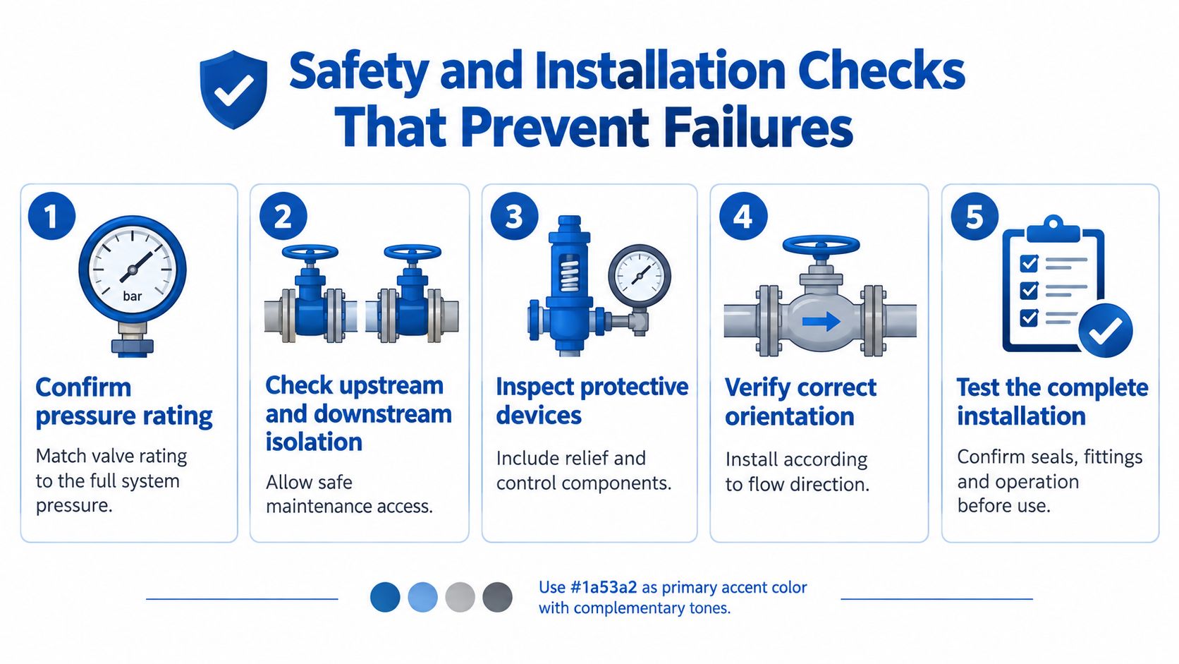
Use a commissioning and inspection sequence that fits the site's risk controls:
- Confirm the valve's identity and limits. Check the manufacturer's documentation, pressure-temperature envelope and intended duty before fitting. A familiar-looking replacement isn't necessarily equivalent.
- Plan isolation before maintenance. Verify pressure on both sides before removal, and document the isolation points. A closed valve alone doesn't prove that trapped pressure has been safely released.
- Check compatibility and condition. Confirm the medium and temperature suit the seats and seals. Inspect for external leakage, damaged actuators and signs of deterioration.
- Inspect the mechanical installation. Check mounting, support and connections for pipe strain. Vibration and poor support can load the valve and joints, particularly on agricultural and mobile machinery.
- Confirm protective devices and access. Make sure the relevant protective devices are functional and that inspection points remain accessible. Select compatible hydraulic fittings and check the complete installed assembly, not only the valve body.
Treat competence as a safety control
People who install, repair or inspect pressure equipment need the competence appropriate to the task. This matters when the work involves isolating a circuit, handling stored energy or deciding whether a component can be returned to service. Where a valve forms part of a hazardous pressure boundary, make sure the inspection arrangements identify the relevant component and allow it to be examined.
Weather, contamination and irregular servicing can make installation details especially important on mobile plant. Keep identification legible, maintain clear records and avoid positioning a valve where routine checks are impractical. If it can't be inspected under the site's arrangements, a technically suitable rating alone won't resolve the maintenance gap.
Choosing a Valve for Heavy Duty Hydraulic Systems
Start with the pressure conditions at the valve, not just the pump specification. Confirm the manufacturer's stated limits at the relevant location, account for the expected pressure peaks, and check the rating at the design temperature. Then match the body, seats, seals and end connections to the hydraulic medium and installation.
| Selection factor | What to confirm |
|---|---|
| Pressure at the valve | Documented PS and operating limits at the relevant location, including expected peaks |
| Temperature | Pressure-temperature limits for the specified valve and service |
| Hydraulic medium | Compatibility of body, ball, seats and seals with the fluid |
| Valve function | Whether the valve is intended for isolation, throttling or both |
| Bore and flow | Whether the bore suits the circuit’s flow requirements |
| End connections | Compatibility with the connected pipework and rated assembly |
| Complete assembly | Pressure limit of the lowest-rated valve, manifold, hose, tube or fitting |
| Maintenance | Space for isolation, inspection and safe servicing |
Decide how the valve will be used
A ball valve designed for isolation shouldn't automatically be used to throttle flow. Closing rapidly against moving, high-flow fluid can produce surge, while partial opening can increase turbulence and loading at the seat. Use throttling only where the specific valve and circuit design permit it. Confirm that the handle or actuator can be operated safely and that its position is clear to the people working on the system.
MA Hydraulics Ltd, based in Scunthorpe, supports engineers with hydraulic component selection, application advice, cross-references for hard-to-find parts and complete assemblies. Its range includes hydraulic valves and manifolds, and the company also assembles Hydronit mini power packs to customer specifications and manufactures bespoke industrial power packs. That support can help when a valve must fit an existing circuit or be specified alongside other hydraulic equipment.
Treat supplier discussions as a way to verify details, not as a substitute for engineering checks. Share the medium, operating conditions, connection requirements and intended function. Ask for the documentation that identifies the valve and its limits, then compare those limits with the whole assembly before ordering.
Taking the Next Step on Your Valve Specification
A reliable specification records the valve's documented pressure limit at the relevant location, checks that limit against the circuit's operating and transient conditions, and confirms that the materials and connections suit the duty. It also keeps the manufacturer's technical information with the equipment so the selection remains traceable after installation or replacement.
Inspection access belongs in the specification, not as an afterthought. For a qualifying pressure system, the operator must have a written scheme of examination before operation. The scheme identifies protective devices and pressure-containing parts whose failure could create danger, and defines the required examination arrangements. Record the valve in the site's pressure-equipment asset register and make sure its identification and inspection points remain accessible.
Before commissioning, confirm the valve's orientation and installation conditions against the manufacturer's information, and record the complete assembly's limits and test arrangements. If any part of the selection is unclear, get application advice before the component is fitted. That is more useful than relying on a catalogue pressure figure that doesn't describe the actual circuit.
For help matching a high-pressure ball valve to its hydraulic medium, connections and complete assembly, phone MA Hydraulics Ltd on 01724 279508 today. The team can assist with component selection, cross-references and hydraulic assemblies, or you can send MA Hydraulics Ltd a message to discuss your application.
