

The fitting that looked right on the maintenance shelf has just caused a problem. The port is labelled 1/2 inch, the gauge connection is labelled 1/4 inch, and a quick ruler measurement appears to support the choice. Yet the thread won't start cleanly, the seal is uncertain, or the installed reducer creates more restriction than the circuit can tolerate.
A 1/2 to 1/4 reducer is more than just a pipe fitting that halves a diameter. In UK hydraulic work, it represents a transition between connection standards, thread forms, sealing methods and flow requirements. Get any one of those wrong and the part may screw together while still being unsuitable for service.
Understanding the 1/2 to 1/4 Reducer Beyond Its Name
A 1/2 to 1/4 reducer adapts a nominal 1/2-inch BSP connection to a nominal 1/4-inch BSP connection. It can resolve a port mismatch between a pump, valve, gauge, actuator, filter or instrumentation branch, but the label describes the connection categories, not a simple geometric conversion.
That distinction matters at the bench. Nominal pipe sizes aren't the same as the fitting's measured outside diameter, and the internal passage may be smaller again. A ruler won't show a 12.7 mm diameter when it is placed across a 1/2-inch BSP thread. The reducer should therefore be specified from the equipment drawings, existing fitting and circuit function, not selected because its outside profile looks close.
The practical question is not, “Will this adapter fit?” It is, “What transition does this circuit require?” A low-flow gauge branch may need a compact reducer, while a pump outlet or actuator supply may need a larger-bore arrangement despite having a smaller threaded port elsewhere.
For general plumbing context, the brass reducer fittings for hot water example is useful because it shows how reducer descriptions combine nominal sizes with male and female orientation. Hydraulic duty demands further checks for pressure, fluid, temperature, sealing and flow.
BSP Thread Standards and Nominal Sizing Explained
British Standard Pipe, or BSP, uses nominal sizing. The size refers to the pipe connection category rather than the direct outside diameter of the thread. For the common sizes discussed here, a 1/2-inch BSP thread has a major diameter of approximately 20.955 mm, while a 1/4-inch BSP thread measures approximately 13.157 mm. These dimensions are provided in the technical product reference for a 1/2-inch by 1/4-inch BSP reducing socket.
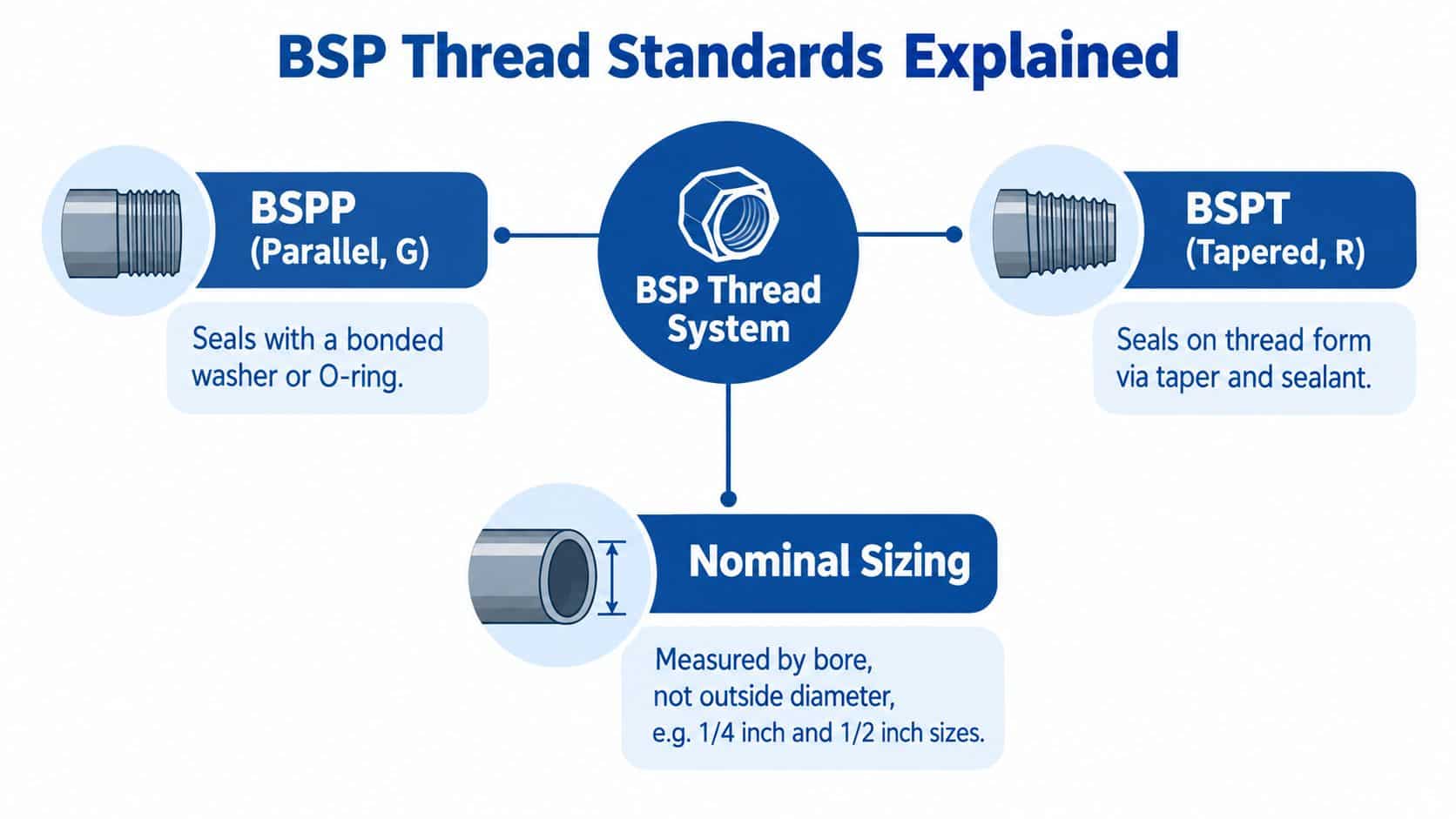
BSP threads use the historical 55-degree Whitworth profile. Pitch is another essential identification point. A typical 1/2-inch BSP thread has 14 threads per inch, whereas a typical 1/4-inch BSP thread has 19 threads per inch, so the two ends aren't interchangeable even before gender and sealing are considered.
BSPP and BSPT are different sealing systems
BSPP, commonly designated G, is parallel. It normally seals against a bonded washer, O-ring or another face-sealing arrangement. The thread positions the component, but the sealing element does the pressure-containment work.
BSPT, or related tapered forms, uses taper at the threaded joint. The threads engage progressively and sealing usually depends on the thread form combined with a suitable sealant. A BSPP male thread and a BSPT female thread shouldn't be treated as a universal pairing only because the nominal size is the same.
When checking a drawing or old fitting, record the nominal size, thread form, pitch, male or female end and sealing arrangement. Don't use a metric diameter reading alone to identify the part. Once the thread form is confirmed, the next decision is how each end must connect to the equipment.
Reducer Orientations and Port Configuration Choices
The most common mistake after identifying the nominal sizes is ordering the wrong gender arrangement. A male 1/2-inch to female 1/4-inch reducer is not interchangeable with a female 1/2-inch to male 1/4-inch version, even though both reduce the nominal connection size.
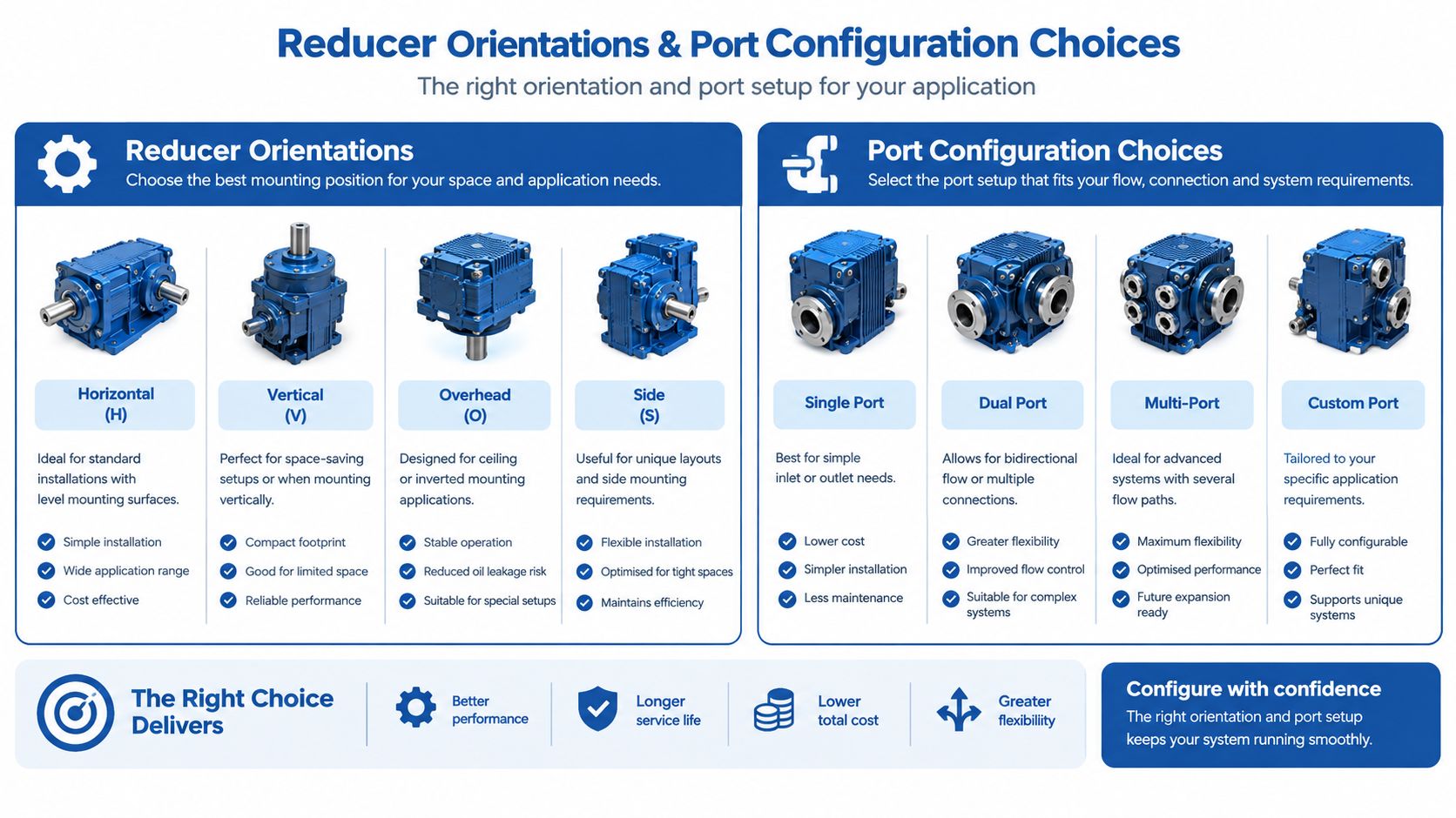
Consider the equipment ports rather than the component name:
- Male 1/2-inch to female 1/4-inch: useful where a larger female manifold or valve port accepts the reducer, while the smaller component presents a male connection.
- Female 1/2-inch to male 1/4-inch: suited to a larger male equipment port when the downstream gauge, valve or adaptor has a female 1/4-inch connection.
- Reducing socket: appropriate where both mating components are male, provided the socket's two internal threads have the correct forms and sealing arrangements.
- Face-seal or O-ring version: preferable where repeated servicing, vibration control or a controlled sealing face matters more than relying on threaded sealant.
A gauge line from a larger valve manifold often needs a different orientation from a pilot connection on a pump. Read the complete designation, including thread standards and end gender. A useful overview of hydraulic fittings types can help when the reducer is only one part of a more complicated connection.
Don't force a BSP fitting into a metric or NPT port to obtain the desired orientation. If the equipment ports don't provide the required male and female combination, use an approved adaptor or change the fitting arrangement.
Why BSP Reducers Still Drive the UK Fluid-Power Market
A small reducer sits inside a large installed base. The British Fluid Power Association estimated the UK fluid-power market at approximately £1.1 billion in 2024, with hydraulics representing about 80% and pneumatics about 20% of that total, as reported in its UK industry facts. On that basis, hydraulic activity represented an estimated £880 million in 2024, calculated as 80% of £1.1 billion.
That market includes replacement equipment, legacy machinery, mobile plant, manufacturing systems and hydraulic assemblies that still use BSP interfaces. Reducers support the practical work of connecting older and newer components, adapting instrumentation, replacing obsolete fittings and resolving different port sizes without redesigning an entire manifold.
The manufacturing base remains relevant too. The same BFPA data reported 194 UK fluid-power equipment businesses in 2025, with the sector growing at a 2.0% compound annual rate between 2020 and 2025. These figures don't make a reducer important by size alone. They show why a standardised interface continues to matter across maintenance and OEM supply chains.
BSP remains commercially widespread in UK engineering, but that familiarity creates a procurement risk. Buyers can recognise “1/2” and “1/4” while overlooking whether the connection is BSPP, BSPT, metric or NPT. A nominal label that looks familiar isn't enough to authorise an order.
Material Options for UK Hydraulic Duty
Material selection should follow the service environment, not the cheapest catalogue line. A reducer used on a protected indoor gauge branch faces different corrosion and temperature conditions from one mounted beside a washdown machine, outdoor power unit or aggressive process fluid.
| Material | Typical advantage | Main caution |
|---|---|---|
| Stainless steel | Strong corrosion resistance and good suitability for demanding environments | Cost, galling risk and the need to confirm fluid and pressure compatibility |
| Carbon steel | Robust option for many hydraulic installations and commonly available in industrial fittings | Requires suitable corrosion protection and shouldn’t be assumed suitable for every environment |
| Brass | Useful for low-pressure instrumentation, pilot and general service applications | Must be checked carefully for pressure, fluid, temperature and mechanical duty |
| Plated or coated steel | Can balance industrial durability with corrosion protection | Coating condition, damaged threads and the manufacturer’s rating need checking |
Stainless steel is justified where external corrosion, washdown, environmental exposure or long service intervals dominate the decision. It isn't automatically the best choice for every hydraulic circuit. Thread galling, assembly practice and compatibility with adjoining materials still need attention.
Carbon steel often suits standard industrial hydraulic duty when the fitting's rating, coating and environment align. Brass can be acceptable for low-pressure gauge or pilot work, but it shouldn't be promoted from an instrumentation branch to a high-load hydraulic connection without explicit manufacturer data.
Check the supplier's material code, not just the product photograph. Confirm maximum allowable pressure, temperature range, fluid compatibility and the complete assembly rating. The reducer's material can't compensate for a hose, mating port or seal that has a lower rating.
Material also affects installation. Soft threads can be damaged by excessive torque, dissimilar metals can complicate corrosion control, and sealants must be compatible with both the fitting and hydraulic fluid. Those details belong on the job sheet before the reducer reaches the manifold.
Installing a BSP Reducer Safely in a Hydraulic Circuit
Begin with the equipment isolated, the hydraulic supply stopped and stored pressure released. Hoses, accumulators, actuators and trapped pockets can retain energy after the pump has stopped, so confirm zero pressure at the relevant test point before loosening the existing fitting.
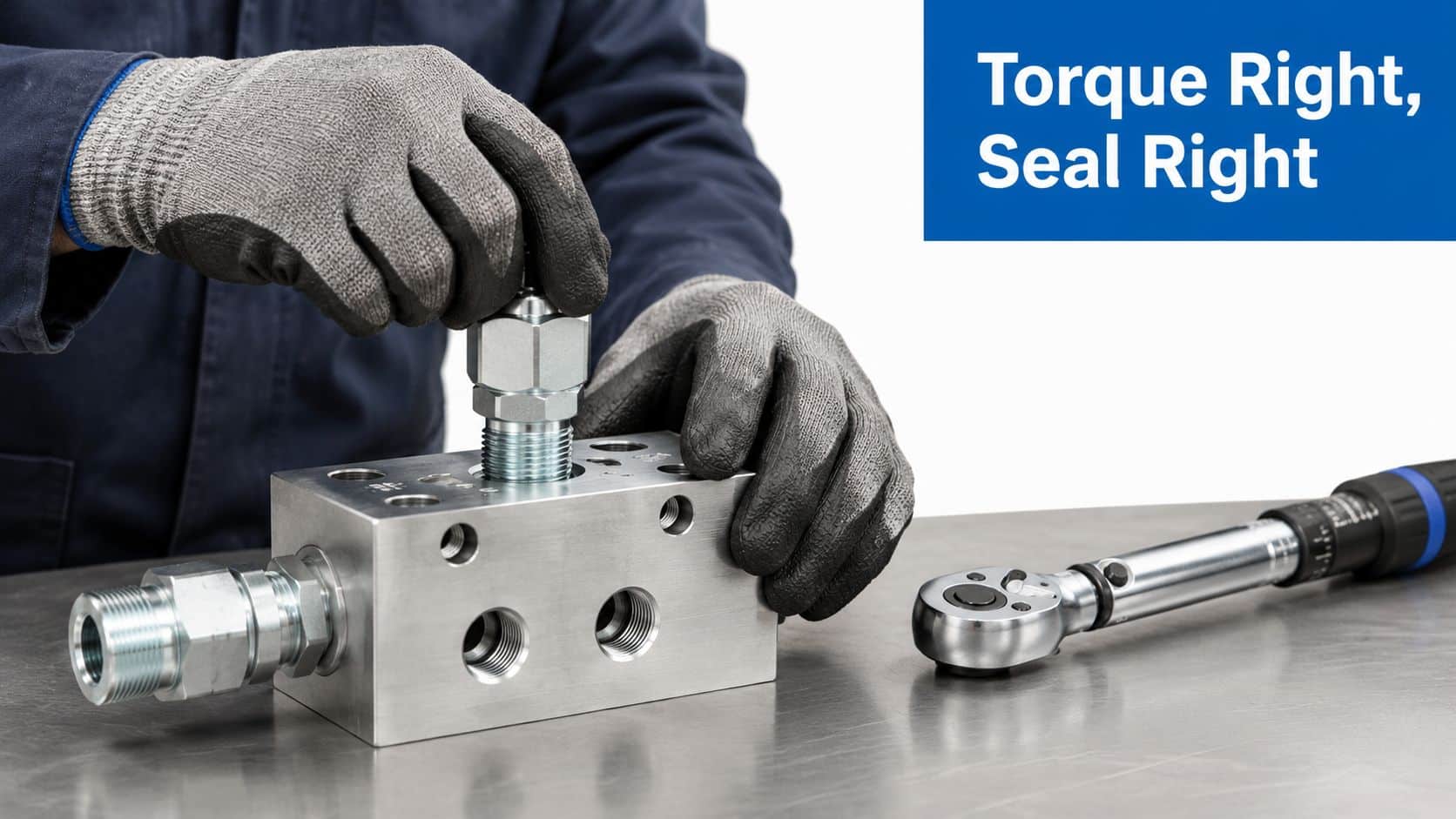
Clean the port and inspect both threads under good light. Remove damaged sealant, dirt and metal fragments, then compare the replacement against the old component and the equipment drawing. Start the reducer by hand. If it doesn't turn smoothly for several threads, stop and investigate instead of using a spanner to overcome resistance.
The sealing method depends on the connection:
- BSPP: use the specified bonded washer, O-ring or face seal. The washer must sit correctly against the sealing face.
- BSPT: use a compatible thread sealant where specified, keeping excess material away from the hydraulic passage.
- Mixed arrangements: confirm the manufacturer's sealing instructions for each end. One reducer may have different sealing requirements on its two sides.
Use the manufacturer's torque value where it is provided. Don't invent a torque setting from the nominal size, because material, thread condition, seal design and port construction all affect the correct value. Hold the receiving block with the correct tooling, keep the reducer aligned and avoid applying side load to a small instrument port.
A pipe or tube connected to the reducer must be supported so vibration doesn't load the threaded joint. After installation, restore pressure gradually, inspect for leaks and verify the circuit's function without placing hands near a suspected leak.
The embedded demonstration should retain its intended aspect ratio on desktop, tablet and mobile displays. Check that the player isn't cropped or stretched and that captions remain visible.
Workshop rule: A dry thread, a clean port and the correct seal are more reliable than extra tightening force.
When a Smaller Outlet Is a Flow Bottleneck
A reducer can be mechanically correct and hydraulically wrong. The 1/4-inch side may become the dominant restriction when oil must pass through it at sustained flow, particularly near a pump, control valve or actuator.
Restriction depends on the actual internal bore, flow rate, oil viscosity, duty cycle and circuit layout. Nominal thread size doesn't tell you the available flow area. A compact fitting that works perfectly on a pressure gauge branch may create pressure loss, heat, noise or sluggish actuator response when inserted into a high-flow line.
The appropriate use cases are usually low-flow branches:
- Gauge connections, where the reducer feeds a measurement point.
- Pilot circuits, where the smaller passage carries control flow rather than actuator flow.
- Sensing lines, where the connection serves an instrument or transducer.
- Auxiliary branches, provided the supplier's pressure-drop information supports the duty.
A mature main line shouldn't be reduced merely because the downstream component has a smaller threaded port. Check the component's actual inlet arrangement, internal bore and required flow. Use supplier pressure-drop data or a validated calculation, and assess the complete route rather than the reducer in isolation.
A smaller threaded outlet isn't automatically unacceptable. It is unacceptable when the circuit demands more flow than that passage can carry without harmful loss.
Maintenance teams should also treat replacement as an energy-control task. Guidance for hydraulic maintenance emphasises safe work equipment, isolation and control of stored energy, while the fitting itself must remain compatible with the circuit's pressure and service conditions.
UK Pressure Equipment Regulations and Conformity
A reducer in a pressurised installation is a pressure-bearing piping component, not merely an accessory. Under the UK Pressure Equipment (Safety) Regulations 2016, piping includes fittings and other pressure-bearing components, and the regulations generally apply where maximum allowable pressure exceeds 0.5 bar, as explained by the Health and Safety Executive guidance on PE(S)R.
For equipment below the applicable pressure and nominal-size thresholds, the item still needs to be safe, designed and manufactured according to sound engineering practice, with adequate instructions. That doesn't remove the need for a documented specification.
Before ordering, record:
- Connection standard and thread form for each end.
- Male or female orientation.
- Material and corrosion requirements.
- Maximum allowable pressure and temperature.
- Hydraulic fluid and seal compatibility.
- Relevant manufacturer test, conformity and installation documentation.
The permitted working pressure of the assembly is the lowest applicable rating among the reducer, mating port, hose or tube and sealing system. A high-rated reducer cannot raise the rating of a weaker adjoining component.
Manufacturers and suppliers have responsibilities for safe design, testing, instructions and required safety information. Where conformity assessment and marking apply, retain the relevant documentation in the equipment file. Instructions should be available in English for UK users.
Hydraulic systems using hydraulic oil aren't covered by the Pressure Systems Safety Regulations 2000 because the relevant-fluid definition excludes hydraulic oils, as noted in HSE guidance for manufacturers and suppliers. That exclusion doesn't remove the need for safe design, compatible hoses and fittings, leak control, isolation and depressurisation procedures.
Cross-References Between BSP and Other Thread Standards
Cross-referencing should identify a compatible replacement, not provide permission to force dissimilar threads together. A 1/2-inch BSP connection may look close to a metric, JIC or NPT alternative, but visual similarity doesn't establish thread compatibility or sealing integrity.
Use this as a decision aid:
| Existing connection | Possible replacement approach | What to do |
|---|---|---|
| 1/2-inch BSP to 1/2-inch BSP | Like-for-like BSP reducer or fitting | Confirm BSPP or BSPT, gender and seal |
| 1/4-inch BSP to metric | Approved BSP-to-metric adaptor | Match the metric thread and sealing arrangement separately |
| BSP to JIC | BSP-to-JIC adaptor with the correct 37-degree flare end | Confirm flare angle and tube connection, not just nominal size |
| BSP to NPT | Approved BSP-to-NPT adaptor | Treat the two thread systems as different and don’t rely on thread sealant to fix a mismatch |
| BSP to an unidentified legacy port | Positive identification before ordering | Measure, inspect and consult the equipment or fitting manufacturer |
Never assume that a BSPT male thread can safely be screwed into an NPT female port. Similar taper does not make the standards interchangeable, and forced assembly can damage threads or produce a leak path.
The same caution applies to metric threads, JIC flare connections and seals. JIC sealing occurs at the flare, not through a pipe thread, so a threaded adaptor may need to provide a completely different end arrangement. For a specific BSP-to-metric requirement, use the 1/4 BSP to metric fitting reference and verify the actual equipment port before selecting a part.
Quick-Reference Checklist Before You Order
Run the specification against the equipment, not the product title. A reliable order should confirm:
- Thread form: BSPP, BSPT, metric, JIC or NPT for every end.
- Nominal size: 1/2-inch and 1/4-inch are connection categories, not measured bore.
- Orientation: male-to-female, female-to-male or reducing socket.
- Seal type: bonded washer, O-ring, tapered-thread sealant or flare.
- Material: suitable for corrosion exposure, fluid and temperature.
- Pressure rating: the assembly is limited by its lowest-rated component.
- Flow duty: actual bore and pressure drop suit the circuit.
- Documentation: retain supplier data, instructions and conformity information where applicable.
- Cross-reference: any metric, JIC or NPT transition uses an approved adaptor.

For a technical image or diagram, repeat key labels in the surrounding text. The UK Government's accessibility guidance for publishing says information conveyed in images should also be available as text, and informative images need useful alternative text rather than a vague label.
Related Components in the Same Hydraulic System
The reducer rarely works alone. Its upstream connection may be a gear pump, power unit, manifold or filter, while the smaller side may feed a gauge, pilot valve, transducer or control block. Port mismatch often appears when a replacement valve or instrument is added to an established circuit.
Check adjacent components such as CETOP directional valves, proportional valves, modular valves, inline circuit valves, gear pumps, gear motors, filters, manifolds, couplings, bellhousings, PTO gearboxes and Hydronit mini power packs. Each can introduce a different port size, thread standard, flow demand or sealing method.
A pump discharge reducer needs a different engineering justification from a gauge adaptor. A valve manifold may accept a compact threaded transition, while a drive system may need a correctly supported hose connection and a larger flow path. Match the reducer to the upstream and downstream requirements together.
Pump-drive selection can also affect the wider circuit. A separate practical guide to pump drives is useful when the hydraulic connection forms part of a motor and pump integration decision, but it doesn't replace checking the fitting's own thread and pressure specification.
Keep the reducer's part number, material, seal type and orientation with the circuit records. That makes the next maintenance intervention faster and reduces the chance of replacing a correctly selected component with a visually similar but incompatible one.
Getting the Right Reducer and the Right Support
When requesting a cross-reference or quotation, send a clear photograph of the installed fitting, the equipment port details and the old part number if available. Include the required 1/2-inch and 1/4-inch end orientation, BSPP or BSPT identification, fluid, pressure, temperature, estimated flow and the intended application.
If the thread is uncertain, don't rely on a ruler photograph alone. Provide measurements, a drawing or the equipment manufacturer's connection data, and explain whether the reducer serves a main line, gauge, pilot, sensing or auxiliary branch. That context determines whether a smaller outlet is appropriate or likely to create a restriction.
A specialist supplier can help with one-off replacements, difficult cross-references and complete hydraulic assemblies. For more involved requirements, support may extend to bespoke power-pack design and Hydronit mini power-pack assembly, including in-house industrial power packs up to 11 kW.
The correct result isn't a reducer that screws into the port. It is a documented connection that seals, carries the required duty and remains serviceable in the actual hydraulic circuit.
MA Hydraulics Ltd can help identify the correct 1/2 to 1/4 reducer, cross-reference difficult fittings and match the part to your hydraulic system or bespoke power-pack requirement. Phone 01724 279508 today, or contact MA Hydraulics Ltd to send the fitting details and application information.
