
A press has stopped mid-cycle. The return-line filter was changed on schedule, the element looked serviceable, and the machine went back into production. Within weeks, the pump failed. The service report blamed contamination, but the actual fault sat in the hydraulic filter housing, where a bypass valve had remained open and allowed unfiltered oil through the circuit.
That situation is more common than many maintenance teams would like. Engineers often specify the element carefully, then treat the housing as a compatible container. In practice, the body, head, seals, bypass valve, pressure rating and installation condition all influence whether the filter delivers the cleanliness level the system needs.
Why the Housing Matters More Than You Think
A new filter element can be fitted correctly and still fail to control contamination. The housing determines whether oil is forced through the media, whether the element remains properly seated, and whether the clean side stays separated from the dirty side. A leaking seal face, early-opening bypass valve, or damaged head can let particles pass without leaving an obvious external sign.
For UK maintenance teams, the result should be judged against ISO 4406 cleanliness codes, not by oil appearance or element age. A patch test or laboratory sample can confirm that the code is poor, but it cannot identify the cause on its own. The investigation must include the element, housing, bypass valve, seals, pressure conditions and installation.
One symptom, several housing faults
An element is often inspected first because it is easy to remove. The housing may have created the same contamination problem through several less visible faults:
- A bypass valve that does not seat: As differential pressure rises, unfiltered oil takes the lower-resistance route.
- A damaged sealing face: Oil can travel around the media and carry particles downstream.
- Corrosion or fatigue: Damage to the body or head can alter both strength and sealing geometry.
- An unsuitable pressure class: A return-line housing may not withstand the pressure and transients present on a pressure line.
- An incorrect element pairing: A fine element in the wrong housing can generate excessive differential pressure or prevent the bypass system from operating as intended.
The practical lesson is straightforward. A report stating “filter contaminated” may describe a housing fault. If the bypass has remained open, replacing the element alone does not restore contamination control or improve the verified ISO 4406 result.
Practical rule: Specify the housing as part of the cleanliness system. Check its pressure capability, bypass behaviour, sealing surfaces and installation condition alongside the element.
Market context also explains why pressure-side housings receive close attention. The UK hydraulic and lube filters market generated USD 189.5 million in revenue in 2022 and is projected to reach USD 212.0 million by 2030, with a projected compound annual growth rate of 1.4% from 2022 to 2030, according to MA Hydraulics' hydraulic filter selection guide. Pressure-side filters represented 37.04% of revenue in 2022, highlighting the demand for housings that protect downstream components while containing system pressure.
What a Hydraulic Filter Housing Actually Does
A filter housing is part of the contamination-control system, not merely a container around the element. If a return filter is correctly specified but the housing allows oil to bypass the media, the particle count downstream can still rise and the expected ISO 4406 cleanliness result will not be achieved.
Contaminated oil enters the inlet and flows into the space around the element. Pressure then drives the oil through the filter media, which retains particles before the cleaner oil reaches the outlet. The housing encloses this route and keeps the element seated, so oil cannot take an uncontrolled path around it.
Contain oil and circuit pressure
The housing must contain hydraulic fluid at the circuit's working pressure, including pressure changes and transient spikes. Suction and return housings are generally designed for lower pressures up to 34 bar. Pressure-line housings may require ratings from 100 to 420 bar, as outlined in STAUFF UK hydraulic filter housing guidance.
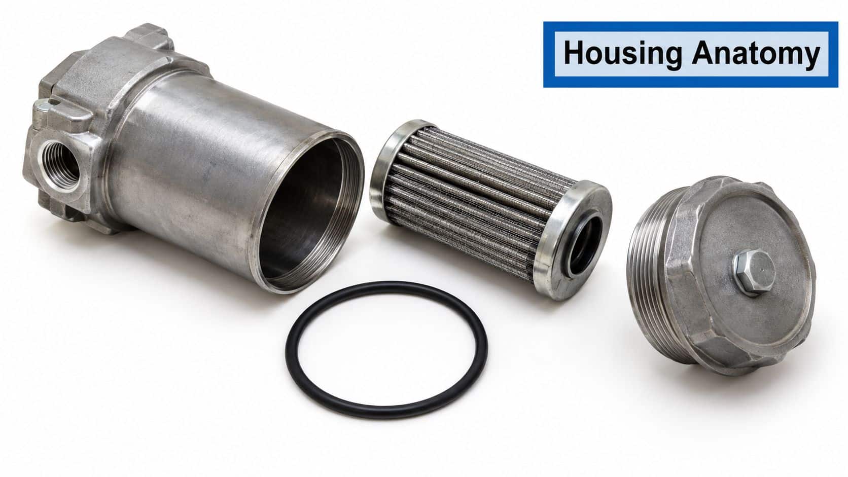
The head carries the ports, mounting points, sealing grooves and, in many designs, the bypass valve and differential indicator connections. Each interface affects contamination control. A damaged sealing face, poor joint or distorted seat can let unfiltered oil reach the outlet without making the element itself defective.
Keep the element stable in service
The element needs firm support during cold starts, high flow and contamination loading. The housing holds the media pack and end caps in position. That support limits seal damage, element collapse and leakage around the element, all of which can worsen the verified ISO 4406 result.
The bypass valve manages excessive differential pressure. It opens when restriction becomes too high, protecting the element and circuit from excessive pressure loss. The protection depends on the correct setting, free movement and a seal that closes properly while the pressure difference remains within the intended range. An indicator or switch then gives the maintenance team a usable warning before restriction affects operation.
Provide reliable condition information
A differential pressure indicator requires pressure tapping points on both sides of the element. The housing provides these reference points for a visual indicator, gauge or electrical signal. Its mounting interface also keeps the assembly secure against vibration and pipe movement, helping the pressure reading reflect actual element loading.
The housing therefore has three linked duties:
- Contain: Hold the fluid, element and circuit pressure safely.
- Support: Keep the media, seals and bypass components correctly aligned.
- Communicate: Provide dependable differential pressure information for maintenance decisions and ISO 4406 verification.
Housing Types and Where Each One Fits
The correct housing type follows the circuit layout. Start with the line location, then check pressure, flow, access, material and the way the element will be replaced. A compact housing in the wrong part of the circuit is still the wrong housing.
An in-line housing is the flexible choice for return and pressure lines. It can be installed in pipework where the element needs protection and the service engineer needs a defined removal point. High-pressure versions may be rated up to 420 bar, but the rating must match the actual circuit, not just the catalogue maximum.
A spin-on canister suits lower-pressure return filtration where rapid change-out matters. The complete canister is replaced, so the technician doesn't normally open a reusable bowl and install a separate element. That reduces handling during a service, but it also means the replacement must match the thread, gasket, flow direction and bypass arrangement.
Tank-top housings sit on or beside a reservoir and are useful for suction-side or return filtration where the tank provides convenient access. They need careful attention to inlet restriction, mounting clearance and the possibility of air entering the suction path.
Manifold-mounted or in-block housings work well where space is restricted and separate pipe joints would create unnecessary leakage paths. They can make a compact installation, although the manifold must be machined and supported correctly.
| Housing Type | Typical Pressure | Best Circuit Location | Common Material | Element Replacement |
|---|---|---|---|---|
| In-line | Return to high-pressure applications, up to 420 bar where specified | Return or pressure line | Aluminium, steel or cast iron | Reusable element |
| Spin-on | Lower-pressure service | Return line | Steel or aluminium | Complete disposable canister |
| Tank-top | Suction or return, subject to design | Reservoir-mounted circuit | Aluminium, steel or cast iron | Reusable element |
| Manifold-mounted | Application-specific | Compact pressure or return blocks | Aluminium, steel or stainless steel | Reusable element or cartridge |
Material choice follows the environment. Aluminium keeps weight down for lighter-duty equipment. Cast iron and steel provide durable options for mobile plant and industrial service. Stainless steel is appropriate where washdown, corrosion resistance or food-grade requirements influence the specification.
Selection check: Mark the housing position on the schematic, record maximum pressure and flow, confirm service access, then check the element format and material against the working environment.
The same layout thinking applies to wider machine design. Teams reviewing production automation from SEA may also need to consider how hydraulic filtration fits around compact automation cells, moving assemblies and restricted maintenance access.
Sizing, Pressure Ratings and Micron Choices
A filter housing can look correctly sized on a drawing and still leave the system exposed. Picture a return circuit operating at 150 l/min. If its housing runs close to bypass pressure during a cold start, the element may be bypassed just when the pump and valves need clean oil. Housing selection therefore links pressure, particle control and flow capacity. Port size is only one part of the decision.
Start by marking the housing's position on the hydraulic schematic. Suction and return housings generally suit lower-pressure service, up to 34 bar where specified. Pressure-line housings may need capability from 100 to 420 bar. Check the circuit's maximum working pressure, transient spikes and frequency of pressure changes, rather than relying only on the normal gauge reading. UK pressure-selection guidance also provides a useful reference for matching housing capability to circuit duty.
Micron selection should follow the sensitivity of the protected component and the required ISO 4406 cleanliness result. A finer element may improve particle removal, but it also creates greater differential pressure as oil cools or contamination loads the media. If the housing is undersized, the bypass can open early and allow unfiltered flow. Treat the element and housing as one contamination-control assembly, then verify the result with oil sampling and ISO 4406 reporting.
The element rating is only one part of that assembly. Confirm efficiency, flow direction, collapse strength and bypass setting against the housing and the circuit. A filter selected by micron value alone may have the wrong pressure capability or insufficient dirt-holding capacity.
Use the bypass margin as a sizing test
A hydraulic filter sizing reference recommends keeping at least a 2:1 ratio between the bypass-valve setting and the pressure differential across a clean element, as described in this hydraulic filter sizing reference. The purpose is practical. Clean-element restriction must remain comfortably below bypass pressure, leaving room for cold oil and normal contamination loading before bypass flow begins.
For the 150 l/min return circuit, that rule points to a housing rated above 300 l/min. The extra capacity gives the element operating room during cold starts and as it collects particles. It also makes the selection easier to confirm during commissioning, because differential pressure should remain below the bypass setting at maximum expected flow.
Use the hydraulic filter selection guide to compare the circuit duty, element specification and housing arrangement before ordering.
| Circuit Location | Typical Working Pressure | Micron Choice | Flow Sizing Check | ISO 4406 Verification |
|---|---|---|---|---|
| Suction line | Up to 34 bar housing class where specified | Coarse protection suited to pump inlet | Keep restriction low and size above maximum pump flow | Set by pump and system maker |
| Return line | Up to 34 bar housing class where specified | Selected for return contamination control | Apply bypass margin at maximum flow | Confirm through oil sampling |
| Pressure line | 100 to 420 bar where specified | Selected for downstream valve or actuator sensitivity | Check clean and loaded differential pressure | Confirm against component needs |
| Charge or auxiliary line | Application-specific | Match charge pump and downstream components | Include cold oil and bypass margin | Confirm against circuit requirements |
Before approval, record maximum flow, including peak demand, and the circuit's maximum and transient pressure. Confirm the element's micron rating, efficiency, flow direction and collapse strength. Check the bypass setting against the clean-element differential and the stated margin. Finally, verify port size, service access, fluid compatibility, temperature range, seal compound and housing material. These checks connect the catalogue choice to an ISO 4406 outcome the maintenance team can measure.
Mounting and Installation Best Practice
A housing protects cleanliness only when its installation keeps contamination out. A correctly sized unit can still worsen an ISO 4406 result if grit enters through the mounting face, a seal is pinched, or pipework bends the filter head.
Prepare the circuit and mounting face
- Isolate the machine. Shut down the power unit, release stored energy and confirm zero residual hydraulic pressure before opening the housing.
- Clean before exposure. Wipe the flange, tank-top port and surrounding area until no visible grit remains. Keep the replacement element on a clean surface.
- Inspect the seal groove. Fit a new O-ring at each service. Check for nicks or corrosion, and use lubricant compatible with the system fluid.
- Tighten evenly. Follow the manufacturer's cross-pattern sequence with a calibrated torque wrench. Housing size may require between 30 and 80 Nm, so use the specified value, not a general estimate.
- Control pipe strain. Align an in-line housing accurately. Around 5° of angular misalignment can transfer bending load into the head and contribute to cracking over time. Use flexible hose or a swivel flange where fixed pipework will not align.
- Complete the checks. Position the air bleed and differential indicator where they can be operated and read safely. Pre-fill when the installation procedure permits, bleed trapped air, restore pressure gradually and check for leaks at operating pressure for 30 minutes before sign-off.
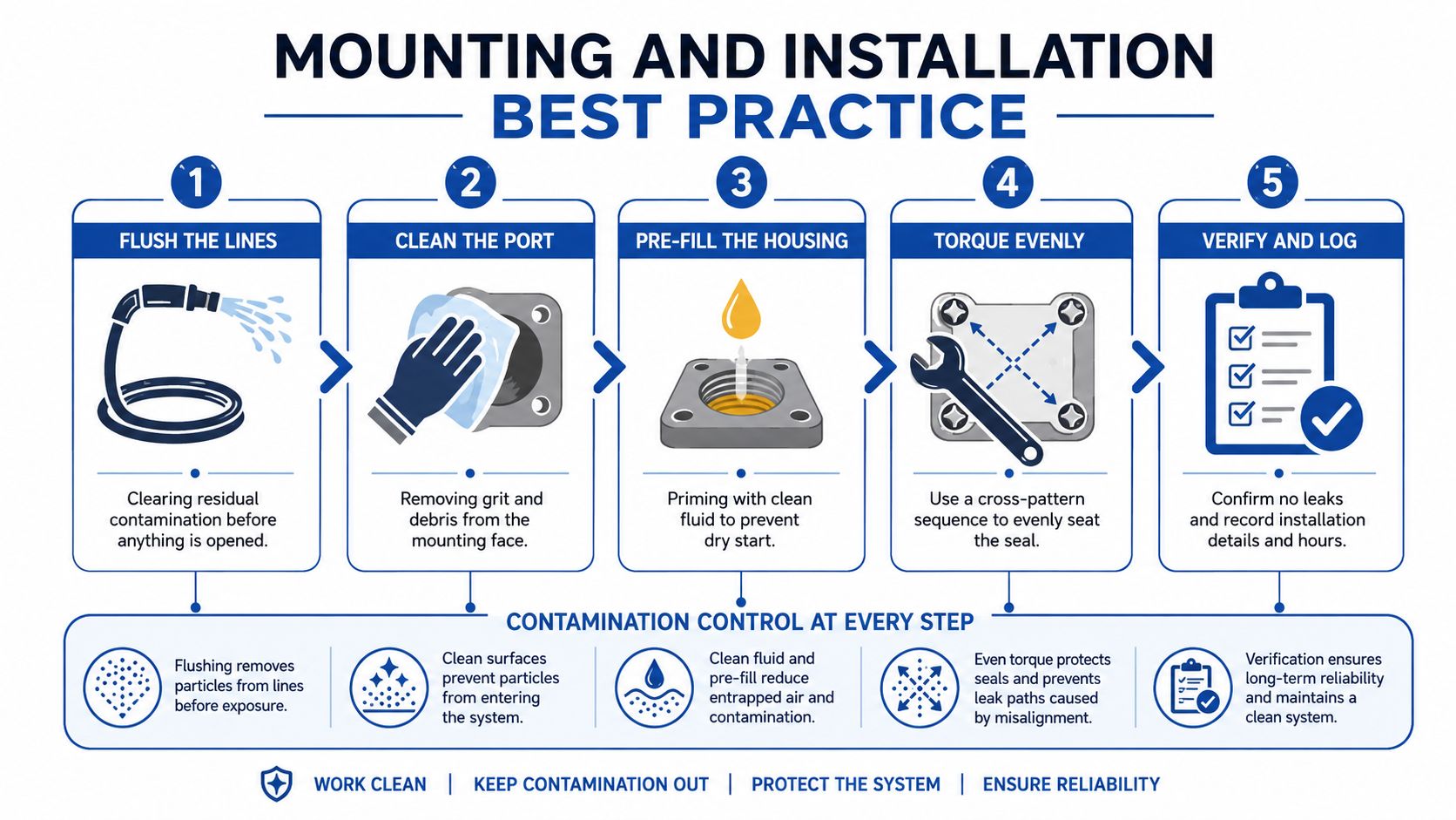
The installation sequence provides a practical fitter's prompt: flush lines, clean the port, pre-fill the housing, torque fasteners evenly and verify the result. Each step limits contamination introduced during the job, helping the maintenance team confirm the intended ISO 4406 cleanliness level through oil sampling.
For element replacement, follow the hydraulic filter change guidance from MA Hydraulics. Keep the clean side covered while removing the old element, fitting the new seal and closing the housing. Record any leakage, restriction or cleanliness change after commissioning.
Service and Maintenance That Actually Protects
A machine can leave the workshop with a new element and still carry contaminated oil. The housing is often the reason. A bypass valve, seal groove, air bleed or mounting face can allow particles or air into the circuit even when the element itself is correctly specified.
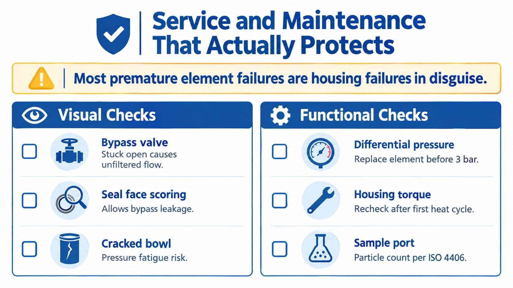
Start with the housing, not just the element. Check for corrosion, distortion, leakage and damage that could change how the element seals or how the bypass valve behaves. Corrosion on an aluminium head, for example, can distort an O-ring groove. A blocked air bleed can trap air, causing poor starting behaviour or abnormal restriction. A bypass valve opening below its specified setting can send unfiltered oil downstream.
Use condition evidence, not habit
Set service intervals from differential pressure, oil condition and ISO 4406 results, then use calendar intervals as a backstop. A clean return-line housing may show around 0.35 bar differential pressure, while a high-pressure unit rated to 420 bar will have its own acceptable range and indicator setting. Treat those figures as application references only. The housing manufacturer's specification governs the decision.
Use a repeatable inspection routine:
- Head: Look for staining, corrosion, cracks and external leakage.
- Bowl: Check for sludge rings, loose debris and damage around the seating area.
- Bypass valve: Confirm free movement and verify the setting during planned testing.
- Differential indicator: Check that it responds and resets correctly.
- Drain plug: Inspect the seal and confirm correct tightening.
- Mounting feet: Look for cracks, elongated holes and signs of vibration.
- Seal face: Remove old material and inspect for scoring before fitting a new O-ring.
The ISO cleanliness code guidance from MA Hydraulics gives UK maintenance teams a consistent way to record particle results. ISO 4406 code 13 corresponds to 40 to 80 particles per millilitre, code 14 to 80 to 160 particles per millilitre, and code 15 to 160 to 320 particles per millilitre. These ranges only support a useful comparison when sampling methods, sample points and operating conditions remain consistent.
Check whether the required cleanliness level has been achieved after one week of initial operation and again after two months. During sampling or fault investigation, record the housing condition, bypass status and element details. Compare the result with the system target, then investigate any deterioration rather than merely fitting a finer element.
Keep a laminated service card with the housing file:
- Machine and circuit location
- Housing model and pressure class
- Element part number and micron rating
- Bypass setting and indicator type
- Differential pressure at inspection
- Seal, bowl, head and mounting condition
- ISO 4406 sample result
- Technician, date and operating hours
Contamination control also depends on the condition of the oil entering the housing. New oil may contain more particles than the system's acceptable ISO 4406 level, so filtration during filling and clean service practice matter. A higher-specification element cannot compensate for bypass leakage, a damaged seal or contamination introduced around a dirty housing. Treat the housing as part of the measurement chain: its seals, valve, vents and service surfaces all influence the cleanliness result the MRO team records.
Frequently Asked Questions About Hydraulic Filter Housings
1. Are spin-on and cartridge housings interchangeable?
No. A spin-on filter normally replaces the complete canister, while a cartridge-style housing accepts a separate element. Confirm the thread, gasket, dimensions, flow direction and bypass arrangement before ordering.
2. How can I confirm that the bypass valve has opened?
Check the differential indicator while the machine is cold and again at normal operating temperature, then compare the reading with the specified bypass setting. If the indicator remains active after a clean, correctly seated element is installed, test the valve and pressure taps rather than assuming the new element is faulty.
3. What torque should I use on a typical M20 cover stud?
Don't select torque from the stud size alone. Use the housing manufacturer's specified Nm figure, the correct tightening sequence and a calibrated wrench, because cover material, seal compression and housing design affect the safe setting.
4. Are aluminium housings suitable for mobile plant?
They can be suitable where pressure, vibration, impact and environmental exposure remain within the manufacturer's limits. For demanding mobile plant, compare aluminium with steel or cast iron and inspect mounting loads, corrosion and service access.
5. Why might a 10 µm absolute element be listed in a 25 µm housing specification?
The housing rating and element rating describe different things. The housing may support a range of element options, while the 10 µm absolute element identifies the selected filtration performance, so verify compatibility, bypass setting and differential pressure before fitting it.
6. When should a return-line filter be taken offline?
Isolate the circuit, bleed the housing safely and service it when the differential indicator or inspection evidence shows that attention is required. Don't open a pressurised bowl, and don't return the machine to service until the seal, air bleed, indicator and leak condition have been checked.
7. How does housing condition affect an ISO 4406 sample?
A leaking seal, stuck bypass or dirty mounting face can allow particles to avoid the element or enter during service. Sample from a representative point, ideally upstream of the housing when investigating incoming contamination and downstream when checking delivered cleanliness, then record the housing condition with the result.
MA Hydraulics Ltd can help you match return filters, spin-on filters and hydraulic filter housings to circuit pressure, flow, element format and contamination-control requirements. Phone 01724 279508 today for application advice and cross-reference support, or visit MA Hydraulics Ltd and send a message through the contact page.
