
The loader is halfway through its shift when the steering goes heavy. The hydraulic gear motor is warm to the touch, the operator wants the machine back immediately, and someone is already reaching for a spanner. That's exactly when a straightforward repair can become a damaged housing, contaminated circuit, or repeat failure.
Gear motor repair isn't just a bearing replacement. A sound job starts with fault isolation, continues through dimensional inspection and correct parts cross-referencing, and ends only after controlled testing. On the bench, the measurements matter more than the confidence of the person holding the tools.
Before You Touch the Motor, Get the Workshop Ready
The first job isn't diagnosis. It's making the area safe.
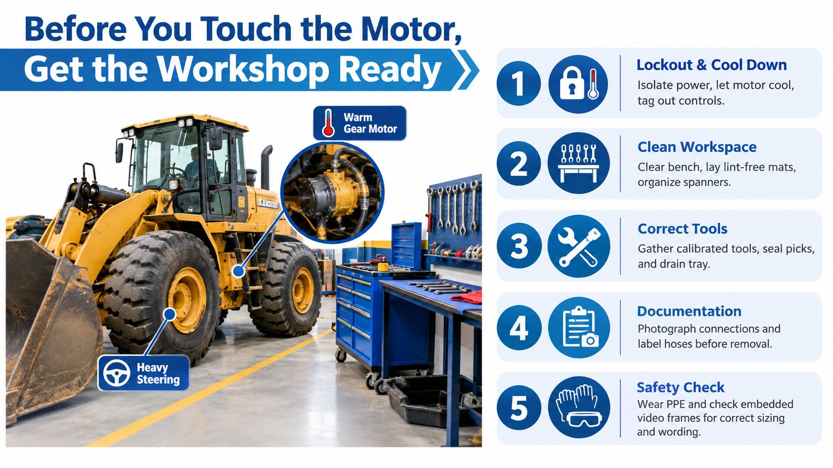
Isolate the hydraulic system at the main isolator, then bleed residual pressure at the pump. Lock out the prime mover with a padlock and tag, and never trust a single valve to hold pressure. Hydraulic circuits can retain energy after the engine stops, particularly around accumulators, trapped hose sections, and loaded actuators.
Let the motor cool before handling it. A warm case may be a useful diagnostic clue, but it's also a burn risk and can make oil sampling misleading. Wear suitable gloves and eye protection, and keep hands clear of couplings and shafts until the machine is positively secured.
Record the installation before removal
Photograph the motor in place. Get clear views of:
- Port orientation: Capture which connection is inlet, outlet, drain, or case return.
- Pipe routing: Photograph hose paths, clamps, bends, and any restrictions.
- Mounting position: Mark the motor's orientation relative to the frame or gearbox.
- Flange alignment: Record scribe marks and any clocking marks before disturbing the mount.
Those photographs prevent avoidable mistakes during refitting. A motor can be mechanically sound and still run incorrectly if its ports are swapped, its drain is routed poorly, or its mounting orientation changes the load on the shaft.
Drain the case oil into a clean pan. Don't tip it straight into a waste container before looking at it. Milky fluid suggests water contamination, brass-coloured swarf can indicate bushing or gear wear, and a burnt smell points towards overheating or lubricant breakdown. Log what you find and retain a sample if the failure is disputed.
Prepare a clean bench
Use a clean sheet of rubber matting, a parts tray, lint-free wipes, a camera, calibrated micrometers, seal picks, and a torque wrench set in Nm, not lb-ft. Keep a labelled bag for shims and another for fasteners.
For sourcing and organising a professional repair bay, workshop equipment for suppliers can help identify suitable benches, storage, lifting equipment, and handling accessories. Preparation may feel slow while a machine is waiting, but a controlled bench usually saves time once the unit is open.
Finding the Fault Without Stripping the Motor
A gear motor shouldn't be condemned because the machine behaves badly. Steering circuits, relief valves, suction lines, couplings, filters, and control valves can all create symptoms that look like internal motor failure.
Start with sound. With the machine safely isolated, turn the input shaft by hand if the arrangement permits it. Feel for tight spots, roughness, or a hard stop. If a running check is necessary, crack a union only under an approved procedure and run the pump briefly at idle, keeping clear of escaping oil. An even hydraulic whine is less concerning than a metallic knock, bearing growl, or persistent hiss.
Next, check temperature by touch only after the system is safe, then use a suitable thermometer for a meaningful comparison. A case that becomes unusually hot during little or no useful work points towards internal leakage, excessive friction, or restricted suction. Don't confuse heat generated upstream at a relief valve with heat created inside the motor.
Measure before forming a conclusion
Connect a 100 bar gauge to the working port and place a flow meter in line. Compare actual flow with the motor nameplate and the machine's specified operating conditions. A measured drop of more than 10 to 15% at rated rpm is the stated trigger for strip-down in this diagnostic workflow, but the machine manufacturer's tolerance and test conditions take priority.
Swapping inlet and outlet hoses can be useful where the motor and circuit design allow it. If the symptom moves with the hoses, suspect the circuit or control arrangement rather than the motor. If the symptom stays with the motor, internal inspection becomes more justified.
| Observation | Likely Cause | Action Before Strip |
|---|---|---|
| Uneven whine or metallic knock | Gear damage, bearing wear, or misalignment | Check coupling, shaft freedom, pressure, and oil condition |
| Hot case during little useful work | Internal leakage, friction, or restricted suction | Check suction path, case drain, and relief operation |
| Weak output with correct drive speed | Worn gears, bypassing control valve, or circuit restriction | Confirm flow and pressure at the motor ports |
| Symptoms change after hose swap | Circuit or porting fault | Trace hoses, valves, and control logic before opening the unit |
| Symptoms remain with the motor | Internal motor fault becomes more likely | Record test readings and prepare a controlled strip-down |
Keep a written record of pressure, flow, temperature, sound, and machine condition. The hydraulic fault-finding techniques guide is useful when the symptoms involve more than the motor itself. Good diagnosis protects a serviceable unit from an unnecessary rebuild.
Stripping the Motor Down Without Causing New Damage
Once the evidence points towards the motor, make the strip-down a continuous, documented bench operation. Wash the outside before opening it, but don't blast contamination into seals, ports, or the shaft area. Clamp the unit in a soft-jaw vice, supporting the shaft without squeezing or distorting the housing.
Use a paint pen to mark the end plate and body before separation. Gear motor housings aren't always symmetrical, and refitting an end plate in a different clock position can cause binding or alter port alignment. Add a second mark if the motor has a flange, bearing carrier, or drain orientation that must return to its original position.
Pull the front flange evenly with the correct puller. Never lever against the shaft seal land. A screwdriver nick may destroy the sealing surface, turn a seal replacement into a shaft repair, or damage the housing if the tool slips.
Protect the parts that set the geometry
Catch the shim pack on a magnetic tray and keep every shim in its original order. Those shims establish gear-mesh preload and end clearance. Losing the sequence, mixing the stack, or cleaning shims without recording their arrangement can create binding, leakage, or excessive backlash during reassembly.
Separate the drive gear first, then the idler gear, and bag each part immediately. Mark the drive and driven positions if the design allows confusion. Don't drag gear teeth across the housing or use the teeth as a pry point. Even small burrs can alter contact patterns.
Photograph the shaft seal before removing it. Record which way the sealing lip and spring face. Seal orientation is easy to forget once the old component is in the bin, particularly when both sides of the seal look similar.
Inspect the shaft seal land under magnification. A groove deeper than 0.1 mm makes the shaft scrap in the stated workshop method, because a fresh seal may not hold reliably on the damaged track. Check the bearing journals, gear faces, bushings, end plates, and O-ring lands for scoring, heat tint, embedded particles, and impact marks.
Bag and tag every fastener with its hole location. Similar-looking metric coarse pitches aren't automatically interchangeable across motor ranges. Record thread condition, washer position, and any locking compound before cleaning the parts.
Common Gear Motor Faults and How to Fix Them
Most bench repairs fall into familiar groups, but the correct fix depends on evidence. Replacing every bearing and seal without checking the gears, housing, shaft, and clearances is how a clean-looking rebuild returns with the same fault.
Bearings
Pitting, brinelling, race wear, and looseness usually show up as rough rotation, growling, heat, or shaft movement. Check the shaft journals with a micrometer. A typical journal inspection may find wear around 0.02 mm, but that figure must be assessed against the manufacturer's limits, bearing fit, load, and shaft design. Don't treat a general workshop value as a universal acceptance limit.
Clean the housing thoroughly before installing a bearing. Remove particles from oilways, corners, and bearing seats, then inspect for fretting or an oval bore. Press the new bearing squarely using the correct fitted sleeve. Striking the wrong race transfers force through the rolling elements and can damage a new bearing before the motor runs.
Seals
A worn shaft seal produces external leakage, while a damaged internal seal can allow pressure or case oil to travel where it shouldn't. Distinguish the main shaft seal from a wiper or dust lip. They may look alike, but they perform different jobs and shouldn't be substituted casually.
Surface finish is frequently missed. The specified shaft-finish range for the seal work described here is Ra 0.2 to 0.4 µm, with the component manufacturer's requirement taking precedence. A polished-looking shaft can still have a groove, roughness, or incorrect lead that quickly damages the replacement seal.
Gears
Scoring across the tooth faces, chipped teeth, pitting, and end-float creep require more than visual approval. Rotate the gears through their working range, inspect contact marks, and measure backlash with a dial indicator fixed to the housing. Hold one gear still, move the mating gear through its free movement, and record the indicator travel.
Polishing marks may be acceptable where tooth form, clearance, and contact remain within specification. Deep scoring, broken teeth, or pitting that has removed the working profile usually makes a gear-set replacement more sensible than reusing the parts.
Lubrication
Viscosity mismatch and contamination create different failure patterns. Oil that's too thick can increase drag and cold-start loading, while oil that's too thin can reduce film strength and increase leakage. Water, dust, fibres, and metal particles damage gears, bearings, and sealing surfaces regardless of the nominal viscosity.
Keep the OEM-specified or OEM-approved hydraulic and gear lubricants on the shelf, along with compatible filters and breathers. Don't mix fluids because both containers say hydraulic oil. Confirm viscosity grade, additive compatibility, temperature range, and seal compatibility from the machine or motor documentation.
Electrical checks
Some gear motors are hydraulic. Others combine a gearbox with an electric motor, and the electrical section must be treated separately. At the terminals, check supply condition, phase balance, insulation resistance, and thermal-switch behaviour before blaming the mechanical assembly.
A megger test can identify an insulation resistance drop, while a clamp meter helps compare running current between phases. A thermal switch that trips may be protecting windings from overload, poor cooling, incorrect voltage, or mechanical drag. The motor may be salvageable if the electrical results are sound and the mechanical load is corrected, but winding damage belongs with an electrical motor specialist.
| Fault | Symptom | Root Cause | Workshop Fix |
|---|---|---|---|
| Bearing damage | Growl, rough shaft rotation, heat | Contamination, overload, poor fit, or fatigue | Replace bearing, clean housing, verify journal and seat |
| Seal failure | Oil leak or pressure bypass | Worn land, incorrect seal, heat, or wrong installation | Check finish, replace seal, inspect shaft and land |
| Gear wear | Low output, noise, scoring, or backlash | Contamination, overload, misalignment, or poor lubrication | Measure tooth form and backlash, replace matched set where required |
| Lubrication fault | Heat, drag, noise, or rapid wear | Wrong viscosity, water, particles, or degraded oil | Flush as appropriate, fit clean filters, use approved fluid |
| Electrical fault | Humming, overload, trip, or uneven running | Phase imbalance, low insulation, thermal protection operation | Test with megger and clamp meter, then repair electrically or mechanically |
For hydraulic pump and motor applications, hydraulic pumps and motors provides a useful reference point for matching the repair decision to the wider circuit rather than treating the motor as an isolated component.
Reassembly and Acceptance Testing
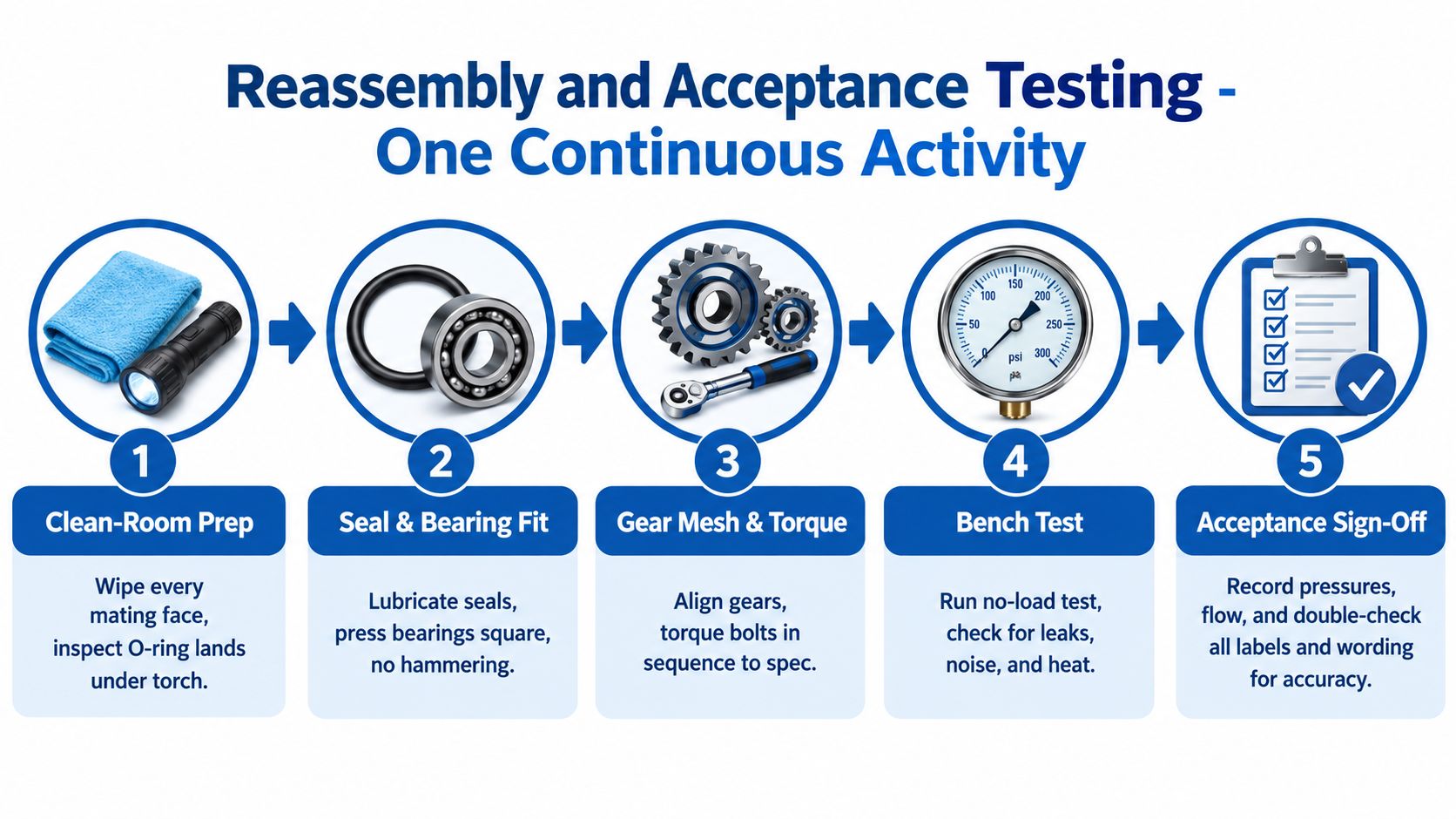
Clean-room discipline starts before the first replacement part goes in. Wipe every mating face, inspect each O-ring land under a torch, and confirm that no lint, abrasive residue, or old seal material remains in an oilway. Shims should be bagged and labelled as soon as they're removed, then rebuilt to the recorded stack height unless the manufacturer specifies a new setting procedure.
Lubricate seals with compatible fluid before fitting. Press bearings squarely, support the correct race, and never hammer directly on the bearing. Align the gears without forcing them into position, then check that the shaft turns smoothly by hand before tightening the body.
Torque is part of the setting
For typical M8 cap screws, a workshop rule of thumb is around 35 Nm. Typical M10 cap screws may be around 65 Nm. These are not universal values. The manufacturer's datasheet, fastener grade, lubrication condition, thread engagement, and joint design always override a general guide.
Tighten in the specified sequence, using a calibrated torque wrench. Uneven tightening can distort the body or end plate, creating tight spots that look like gear damage. Record the actual torque and any thread-locking product used.
Run the repaired motor under controlled conditions
Run the motor on a suitable test rig. Start at no load for 10 minutes, then run for 10 minutes at 30% rated pressure, followed by 30 minutes at full duty, using the manufacturer's limits and safe test procedures. Watch for leaks at every joint and listen continuously rather than relying only on the final reading.
Acceptance rule: A repaired motor must pass measured checks, not just look tidy on the bench.
Check case-drain flow, operating temperature after the run-in, pressure stability, and shaft behaviour. Make both load and no-load observations. A healthy unit should creep without a persistent growl, knock, or sharp change in sound under load.
The UK occupational standards support this controlled approach. Corrective hydraulic maintenance on land-based equipment is carried out in accordance with approved procedures under the UK National Occupational Standard for hydraulic systems, while Skills England's construction equipment standard requires repaired or refurbished critical components to undergo function and safety testing before recommissioning, in line with legislative and manufacturer requirements.
The embedded video should remain large enough for its controls to be usable. Its frame uses a responsive aspect ratio, but check the rendered page rather than assuming the source markup displays correctly. Accessibility guidance from the University of Bath on iframe embeds says an iframe should have a descriptive title attribute, and the related guidance says video should not be rendered below 50% page width so controls remain legible. The frame wording and any text visible in the video or infographic should also be checked for accurate spelling and technical terminology.
Preventive Maintenance That Actually Stops Repeat Failures
A machine that returns to work after a rebuild needs a maintenance routine people can follow. Tie each check to machine hours, record the result, and give the operator a clear escalation point.
At the 250-hour interval, take an oil sample, inspect the breather, and spend a short listening period at each motor housing with a mechanic's stethoscope. Note any change in whine, knock, or bearing rumble rather than writing “sounds fine”. Check the oil's colour and contamination, inspect for seepage, and look at mounts and alignment.
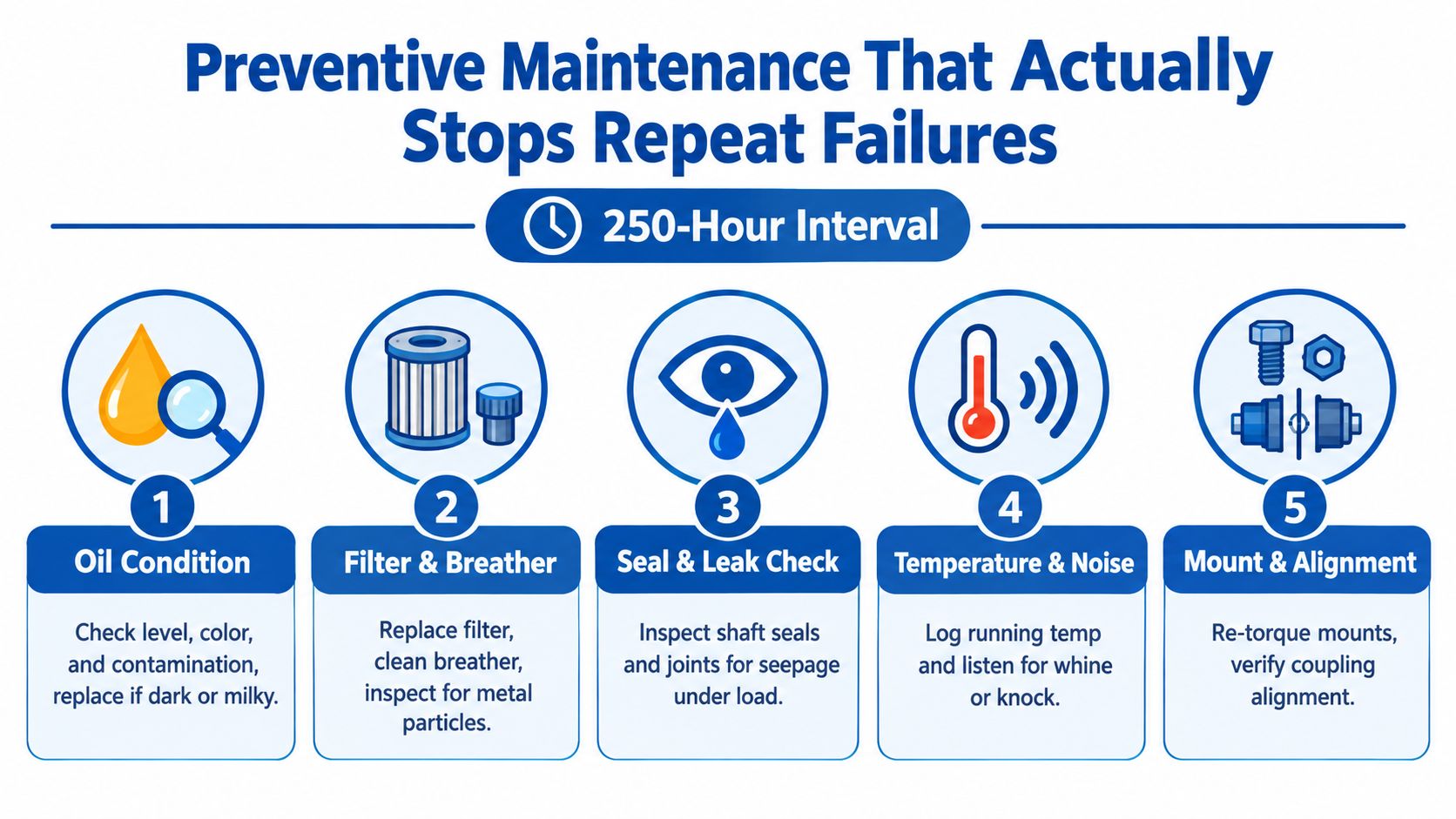
At the 1,000-hour interval, change the fluid, replace the filter, clean the breather, and check case-drain flow against the manufacturer's tolerance. If the sample contains metal, don't hide the result by filling with fresh oil. Find the source before the particles circulate through another repaired motor.
At the 2,000-hour interval, remove the motor for inspection even if it still sounds acceptable. Seals can harden and bearing clearances can grow without producing an obvious failure signal during a routine walk-round.
Make the record useful
The most cost-effective habit is a proper component history. Log every motor swap with its serial number, machine hours, operating position, fault mode, oil condition, and parts fitted. When the same machine repeats the same failure, that record exposes installation, alignment, contamination, loading, and specification problems that a parts invoice won't show.
The UK standard for maintaining fluid power equipment reinforces the need for corrective work under approved procedures. A repeat failure investigation should follow the same discipline as the original repair, with recorded evidence rather than guesswork.
Parts, Cross-References and When to Call a UK Specialist
Parts selection starts with the original identification plate and ends with dimensional confirmation. Match bearings, seals, gears, shafts, ports, rotation, displacement, pressure rating, mounting pattern, and shaft configuration. A bearing cross-reference may point towards SKF, FAG, or Timken, while seal options may include NOK or Hallite, but the equivalent still has to match the application and fit.
For gear sets, compare outside dimensions, tooth form, module, width, pressure rating, and shaft engagement. Don't mix imperial and metric shim stacks. A part can appear close enough on the bench and still produce the wrong end clearance once the housing is torqued.
Decide where the job belongs
| Factor | Repair In-House | Send to MA Hydraulics |
|---|---|---|
| Motor size | Small, familiar unit with accessible parts | Larger unit requiring lifting, specialised tooling, or controlled measurement |
| Hours on unit | Low wear history and clear fault mode | Long service history, unknown maintenance, or repeated failure |
| Gear-set condition | Light marking that measures within specification | Pitting, deep scuffing, broken teeth, or uncertain contact pattern |
| Warranty position | No warranty or liability concern | Warranty work, customer-critical equipment, or traceable repair required |
| Test capability | Suitable gauges, flow measurement, and safe test rig available | No reliable acceptance rig or no means to verify case-drain performance |
The UK repair market has substantial capacity. The electric motor repair market is estimated at £1.2 billion to £1.8 billion annually, supported by roughly 400 to 500 active repair facilities and an installed base exceeding 15 million industrial motors, according to the UK electric motor repair market analysis. The same source describes a repair environment where inspection, stripping, measurement, and refurbishment are often preferred to automatic replacement.
For larger units, unusual materials, badly damaged gear sets, or warranty-controlled work, use a specialist rather than taking a gamble on an incomplete rebuild. MA Hydraulics Ltd can support hydraulic component selection, gear motor replacement, fault discussion, and repair-related requirements, with after-sales support described through its hydraulic after-sales service. Confirm the current turnaround, scope, and parts availability when requesting a quotation. UK emergency hydraulic providers commonly build rapid field response into their service model, including 60 to 90 minute ETA targets, a stated one-hour response goal depending on location and traffic, and 24/7, 365-day UK coverage, as described by UK Hose hydraulic support. That speed matters when a gear motor sits inside a wider breakdown workflow with hoses, pumps, and actuators.
Don't choose repair or replacement from the oil leak alone. Choose it from the measured condition of the housing, shaft, gears, bearings, clearances, and test results.
For a quote and failure-mode discussion, phone 01724 279508 today or send the details through the contact route below.
MA Hydraulics Ltd supplies hydraulic gear motors and supports component selection, repair decisions, cross-references, and bespoke hydraulic power requirements for mobile and industrial equipment. Visit MA Hydraulics Ltd with the motor identification details, symptoms, measurements, and photographs, or phone 01724 279508 today, or send us a message at https://www.mahydraulics.co.uk/contact-us/.
