
You're halfway through specifying a replacement motor when the catalogue rating starts to look reassuring. The displacement matches, the shaft speed appears acceptable and the pressure figure leaves some room. Yet the machine runs for long shifts, sees cold starts, dirty surroundings and repeated load changes. The motor won't experience a catalogue test bench. It'll experience the actual duty cycle on your farm machine, conveyor, mobile plant or production line.
A high speed hydraulic gear motor can be a practical, compact choice where fast rotation, straightforward construction and dependable service matter. The reliable result comes from more than selecting the highest rpm figure. You need to understand how flow, displacement, pressure, torque, heat, contamination and case drainage interact.
The UK hydraulics market provides useful context. It was valued at about $2.46 billion in 2025 and is projected to reach about $2.73 billion by 2030, implying a 2.1% CAGR, according to UK hydraulic gear motor market context. That mature market makes service life and downtime practical buying considerations, not afterthoughts.
Why High Speed Hydraulic Gear Motors Matter on UK Machines
A conveyor roller that accelerates too slowly can hold up an entire line. Increasing motor displacement may raise starting torque, yet it also demands more flow and can reduce shaft speed when pump capacity is fixed. The correct choice depends on the duty cycle, not just the largest figure in a catalogue.
A high speed gear motor suits a machine that needs rotational speed from controlled hydraulic flow, especially where installation space is limited and repeated cycling is expected. It may be a poor fit for a heavy load running slowly, severe shock loading or precise variable-speed control. Those duties can require a different motor arrangement.
UK duty cycles are harsher than the catalogue
A UK machine may face changing weather, dust, moisture and irregular loading in the same working week. Agricultural equipment can draw straw dust and bio-residues towards exposed components. Materials-handling machinery may repeat start-stop cycles, while mobile plant combines cold starts, vibration, tight installation space and sudden load changes.
These conditions make three checks central to selection:
- How much heat will the motor create? Hydraulic losses become heat, particularly when the motor operates close to its limits for extended periods. Heat must be considered alongside cooling capacity and the length of each run.
- How clean is the oil in practice? Particles wear gear faces, bushings, bearings and seals. A motor described as contamination-tolerant still depends on suitable filtration and clean fluid.
- Where does leakage go? Internal leakage needs a correctly sized case-drain route. If case pressure rises, it can damage the shaft seal and shorten motor life.
Case drainage is easy to overlook during a replacement. A motor can show acceptable pressure and speed on paper while suffering premature seal failure because the return path is restricted, incorrectly routed or exposed to excessive back pressure.
A useful maintenance approach links selection with data-driven hydraulic maintenance. Performance records, fluid samples and temperature trends help reveal declining motor health before lost speed or torque stops production.
The practical questions are therefore clear: can the motor shed the heat generated during repeated operation, can the system control contamination, and can the case drain remain within its permitted pressure? The following guidance examines those three failure routes while covering specification, application and installation decisions.
Workshop rule: Select for the load the motor will see repeatedly, not the highest number printed in the product table.
How a High Speed Hydraulic Gear Motor Works
On a UK machine, a high-speed gear motor may run smoothly at the start of a shift, then slow as oil temperature rises or contamination increases. Understanding the internal flow path explains why speed, torque, heat and case drainage must be considered together.
A gear motor uses two meshing gears inside a close-fitting housing. Pressurised hydraulic fluid enters at the inlet and pushes against the gear teeth, turning the driven gear and shaft. The second gear carries fluid around the housing, while the meshing teeth limit direct flow back towards the inlet.
Start with displacement
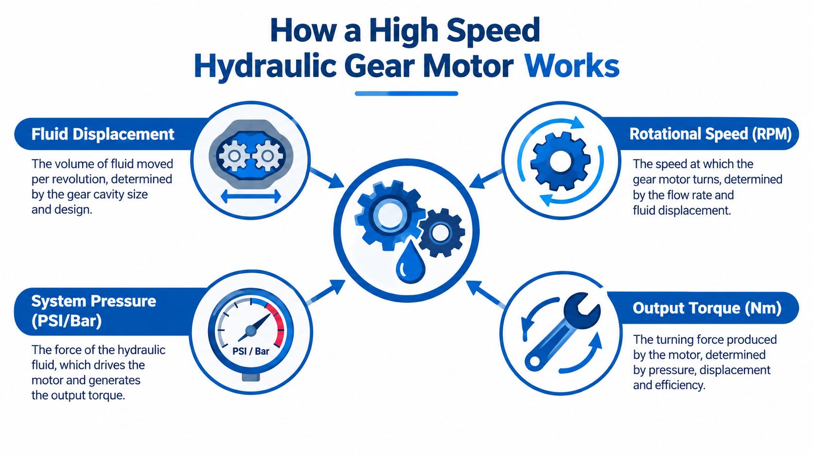
Displacement is the volume of hydraulic fluid associated with one shaft revolution, measured in cubic centimetres per revolution. A larger displacement generally gives more torque at a given pressure, but it requires more flow to reach the same speed.
For a fixed-displacement motor, the basic relationships are:
- More pump flow produces more rotational speed.
- More pressure across the motor produces more torque.
- More displacement increases torque potential but reduces speed for a given flow.
- Internal leakage makes actual output lower than the ideal calculation.
The ideal calculation assumes that every part of the supplied flow creates useful rotation. In service, clearances, friction, oil viscosity and wear reduce the result. Rising temperature can reduce viscosity, increasing leakage and lowering volumetric efficiency.
Pressure creates torque
Pressure provides the force that turns the gears. If the shaft meets greater resistance, the circuit must develop more pressure, provided the pump, relief valve, hoses and motor are rated for that condition.
Torque describes turning force. Power combines turning force with rotational speed. A small motor running quickly can deliver useful power, yet struggle to start a high-inertia load if starting torque is insufficient. A larger motor can provide stronger turning force, although it may need more flow and occupy more space.
Speed is a system result
Motor speed depends on pump flow, displacement and volumetric losses. A high-speed rating states what the component may tolerate under specified conditions. It does not confirm that the machine can supply the required flow, remove the resulting heat or maintain bearing and seal life at that speed.
Selection therefore begins with the driven load and available flow, followed by checks on the motor's rated operating envelope. Repeated operation beyond that envelope can increase wear, noise, leakage and temperature. Case drainage also needs a clear, low-resistance route, because trapped leakage raises case pressure and can damage the shaft seal.
Key Specifications Engineers Must Understand
At the workshop bench, two motors can show similar displacement, rpm and pressure figures yet behave very differently in service. The useful comparison is how those values work together, alongside heat removal, contamination control and case drainage.
Read the main figures as a system
The UK-facing technical catalogue for cast-iron gear pumps and motors gives pressure bands up to more than 210 bar, contamination targets of ISO 4406 class 21/19/16 and 20/18/15 depending on pressure, and a practical hydromechanical efficiency assumption of 0.85 under working conditions. These benchmarks appear in the cast-iron gear pump and motor technical catalogue.
Use the figures below as a screening framework, then confirm the selected motor's own data sheet and duty limits.
| Parameter | Useful reference | Notes |
|---|---|---|
| Speed | Set by pump flow, displacement and losses | Confirm continuous, intermittent and peak limits separately. |
| Displacement | Select to balance available flow and required torque | Larger displacement normally favours torque, while available flow limits speed. |
| Torque | Check starting, running and peak requirements | Do not rely only on nominal output. |
| Pressure | Up to more than 210 bar in applicable catalogue bands | Confirm whether the value is continuous, intermittent or peak. |
| Efficiency | About 0.85 hydromechanical assumption under working conditions | Treat this as an operating-point value affected by pressure, speed, viscosity and wear. |
| Fluid cleanliness | ISO 4406 class 21/19/16 or 20/18/15, depending on pressure | Use the stricter target where pressure and duty require it. |
Speed and displacement are linked
Pump flow and displacement set shaft speed. With limited flow, a larger displacement gives more turning force but lower rpm. A small displacement can achieve higher speed, provided the motor still handles starting torque, continuous load and pressure without excessive leakage or heat.
Ask for the continuous speed, intermittent speed, maximum pressure, continuous pressure, shaft loading limits and recommended fluid viscosity. Physical fit alone is not enough. A coupling can impose radial load, while operation near the upper speed limit can shorten bearing and seal life.
Efficiency is a heat question
Losses become heat in the oil, casing and surrounding installation. Check reservoir capacity, cooling, ambient temperature and line back pressure against the actual duty cycle, especially where the motor runs quickly for long periods or starts under load.
Use MA Hydraulics' information on hydraulic gear motors and related selection details as an initial reference, then request performance curves for the chosen motor and working fluid. Also confirm a low-resistance case-drain route where the design requires one. A catalogue boundary does not show whether the motor will stay cool, clean and reliable on the machine.
Where High Speed Gear Motors Are Used Across UK Industry
A slurry agitator, conveyor and production mixer can all use a high speed gear motor, yet their working conditions are quite different. Selection depends on more than the required rpm. Heat, contamination, starting resistance and case drainage decide whether the motor remains reliable through a UK duty cycle.
Agricultural equipment often needs sealed construction and simple replacement. Seeders, feeder wagons and slurry agitators encounter dust, moisture and residue, so filtration and shaft-seal protection matter alongside speed. A motor may run steadily, then meet a sudden rise in resistance as material shifts.
Materials-handling systems need responsive rotation, but fast cycling does not remove the need for controlled starting and stopping. Conveyors, pallet equipment and winches should be checked for starting torque, braking and load inertia. A trailer or hydraulic platform also needs its motor, valves and mechanical load assessed together, so buyers reviewing trailer selection for heavy loads should specify the complete load-handling arrangement.
Mobile plant adds vibration, temperature changes and restricted installation space. Telehandlers, compact loaders, road planers and snow ploughs may need protected case-drain routing and allowance for cold-start pressure shocks. Manufacturing lines, mixers, presses and extrusion feeders usually require repeatable output as resistance changes, with heat rejection and oil cleanliness monitored throughout production.
| UK Application | Indicative Displacement (cc/rev) | Indicative Peak Speed (rpm) | Indicative Pressure Band (bar) | Practical Cleanliness Guidance |
|---|---|---|---|---|
| Agriculture | 2 to 25 | 500 to 2,500 | 150 to 250 | Protect against dust, moisture and residue |
| Materials handling | 2 to 50 | 500 to 3,000 | 150 to 250 | Control contamination during frequent cycling |
| Mobile plant | 5 to 50 | 400 to 2,500 | 200 to 300 peak | Allow for shock loads and cold starts |
| Manufacturing | 2 to 40 | 750 to 3,000 | 150 to 250 | Maintain filtration and check oil condition |
These figures are indicative selection bands, not motor ratings. Actual suitability still depends on displacement, flow, pressure, viscosity, temperature and the full speed profile. A smaller motor driven quickly can generate more heat than its catalogue speed alone suggests, while restricted case drainage can raise seal or bearing stress.
Before ordering, ask the supplier for the motor's performance curve at the actual fluid viscosity and operating temperature, including case-drain limits where applicable.
How to Select the Right Motor for the Duty Cycle
Start at the driven shaft, not at the motor shelf. Write down the required speed, the torque needed to start, the torque during normal running and the load changes that occur during a complete machine cycle.
Build the duty picture
A motor that runs steadily at a moderate load may be a better choice than one that repeatedly starts against a heavy inertia. Record how often the machine accelerates, reverses, stalls or encounters an obstruction. Idle time matters because the average thermal load can look comfortable while repeated peaks still damage the drive.
Then match speed and torque to the driven component. Check the inertia, coupling arrangement, braking method and any gearbox between the motor and load. If you're unsure how the hydraulic and mechanical sides interact, use the hydraulic motor sizing guidance alongside the selected manufacturer's calculations.
Check flow, pressure and temperature
Use available pump flow to keep the motor within its speed envelope. Exceeding the speed limit can shorten bearing and seal life, while selecting excessive displacement can leave the motor too slow or demand more pressure than the circuit can provide.
Pressure should sit comfortably below the motor's applicable maximum during continuous work. Allow for hot installations, restricted return lines and relief-valve response. A motor mounted near an engine bay or foundry process may need derating because fluid temperature and surrounding air reduce the available thermal margin.
A useful external reference for comparing motor selection factors is the E & I Sales motor selection guide, but hydraulic motor decisions must still follow the hydraulic manufacturer's pressure, speed, fluid and case-pressure limits.
Confirm cleanliness, drainage and fit
The selection process isn't complete until the installation details are checked:
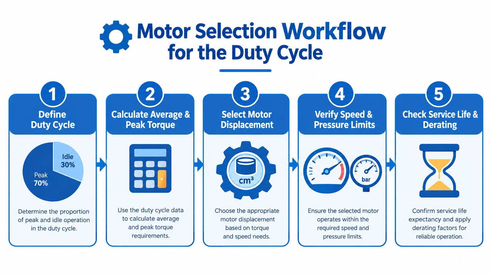
- Define the duty cycle. Separate idle, normal, peak and shock conditions.
- Calculate torque needs. Include starting inertia and mechanical transmission losses.
- Select displacement. Use pump flow and required speed together.
- Verify limits. Check continuous and peak speed, pressure, temperature and shaft loading.
- Confirm protection. Specify filtration, fluid compatibility, case drain routing, flange, shaft and coupling.
For general industrial use, the specified plan calls for cleanliness to at least ISO 4406 18/16/13, tightening to 17/15/12 for servo or high-cycle mobile service. These targets must be reconciled with the selected motor documentation and the actual circuit filtration strategy. Don't assume a motor's heavy-duty construction removes the need for clean oil.
Installation and Maintenance Best Practice
A high-speed motor can be damaged before it completes its first meaningful shift. Alignment, pipe cleanliness and case-drain routing are installation tasks, not optional finishing details.
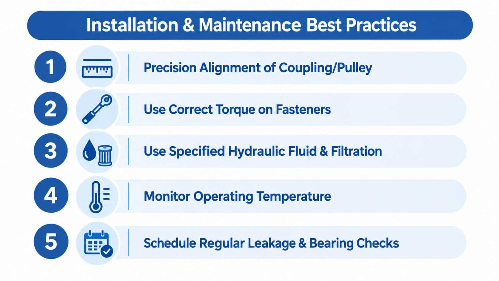
Begin with the mechanical connection. Align the coupling or pulley carefully and check for angular and parallel errors. At high shaft speed, misalignment increases bearing loading and can also damage the shaft seal. Confirm that the driven equipment doesn't impose side or end loads beyond the motor's permitted values.
Protect the hydraulic path
Size inlet and return lines to avoid starvation, excessive restriction and cavitation. The specified installation guidance uses flow velocity below roughly 4.5 m/s on the pressure side and 3 m/s on return, so use the manufacturer's hydraulic design limits when finalising pipe sizes.
The case drain deserves separate attention. Route it directly to the reservoir, not into a pressurised return line. A low-mounted motor needs a drain arrangement that prevents the casing from emptying during shutdown, because dry running can damage internal surfaces and seals.
Flush new pipework before connecting the motor. Welding swarf, mill scale, thread debris and hose contamination can reach the gear set quickly. Clean assembly practices protect the component far more effectively than trying to remove damage after the first failure.
Make wear visible
Monitor case-drain flow as an indicator of internal wear. Take fluid samples for particle counts and water content, and replace filters according to the manufacturer's service guidance rather than relying only on a calendar interval.
Re-torque mounting bolts after the first 50 hours, check the shaft seal at each service and keep a written operating-temperature log. A gradual temperature increase often gives the maintenance team time to find restriction, contamination, overloading or internal leakage before the motor stops the machine.
For installations where the motor and driven shaft need a reliable mechanical connection, review the appropriate motor shaft couplings before ordering the motor. Fit, alignment and permitted shaft loads must agree.
Reading Performance Curves and Troubleshooting Common Faults
Performance curves show how a motor behaves at particular test conditions. They don't replace a duty-cycle calculation. Read the torque versus pressure curve first, then compare the required load torque with the motor's available output at the intended pressure.
The speed versus flow curve tells you whether the pump can provide the flow needed for the target rpm. Next, inspect volumetric efficiency against speed. Rising leakage at higher speed can reduce actual output and increase heat. Overall efficiency then shows where the motor converts the available hydraulic input into useful mechanical output with the least loss.
Plot the real operating point
Use the manufacturer's stated fluid viscosity and temperature conditions when interpreting the curves. A different viscosity can alter leakage, friction, noise and efficiency. If the machine operates across a broad temperature range, evaluate both cold-start behaviour and hot continuous running.
Mark the normal operating point, peak load and acceleration condition. Leave practical margin below speed and pressure limits, especially where the load changes quickly or the installation has back pressure in the drain or return circuit.
Troubleshoot before dismantling
| Symptom | Probable causes | First corrective action |
|---|---|---|
| Speed falls under load | Insufficient flow, excessive internal leakage, contamination or pressure limitation | Check measured flow and pressure, inspect filtration and compare case-drain behaviour with the manufacturer’s guidance. |
| Case drain flow rises | Internal wear, excessive pressure or unsuitable viscosity | Check case pressure and fluid condition before deciding whether the motor needs overhaul. |
| Motor overheats | Excessive duty, restriction, high leakage, wrong fluid grade or poor cooling | Measure temperature and pressure across the operating cycle, then remove avoidable restrictions. |
| Noisy operation | Air ingress, cavitation, starvation, misalignment or contaminated fluid | Check inlet conditions, reservoir level, pipe joints, alignment and filter condition. |
| Shaft seal leaks | Excessive case pressure, worn seal, shaft damage or misalignment | Verify the drain route and case pressure, then inspect the shaft and coupling. |
| External leak paths appear | Loose fittings, damaged seals or housing damage | Clean the area, identify the source under safe operating conditions and repair the cause rather than only tightening randomly. |
Curves are controlled test results. A real UK installation may have colder starts, dirtier oil, restricted plumbing, variable loads and less cooling than the test arrangement. Treat the curves as a map, then validate the route with measured speed, pressure, temperature and case-drain condition.
Key Takeaways and Getting the Right Motor for Your Application
A high speed hydraulic gear motor rewards disciplined specification more than catalogue enthusiasm. Match displacement to available flow, match pressure to the actual torque requirement and check speed against the driven component's continuous operating needs.
The critical protections are practical:
- Size around the duty cycle. Separate normal, peak, idle and shock conditions.
- Control heat. Check efficiency, fluid temperature, ambient conditions and return restrictions.
- Protect the gears. Use the applicable ISO 4406 cleanliness target and flush new pipework before connection.
- Route the case drain correctly. Keep case pressure within the manufacturer's limit and return leakage safely to the reservoir.
- Respect derating. Don't run above rated speed for long periods or treat a peak pressure as a continuous working pressure.
- Record condition. Temperature, fluid samples, filter condition, noise and case-drain behaviour reveal deterioration early.
UK buyers can ask MA Hydraulics Ltd to help review gear motor selection, replacement compatibility, mounting, shaft configuration, duty cycle and contamination-control requirements. The company supplies hydraulic gear motors, including Vivoil unidirectional and reversible options in Groups 0 to 3, alongside related hydraulic components and bespoke power solutions.
MA Hydraulics Ltd can help you match a hydraulic gear motor to your flow, pressure, speed, mounting and real duty-cycle requirements, whether you need a replacement or a complete application review. Visit MA Hydraulics Ltd or phone 01724 279508 today, or send us a message with your motor details and operating conditions.
