
A machine is down because a compact valve that starts or stops flow in a power pack has stopped responding. The coil has power, the pump is running, and the operator is waiting, but the actuator won't move. In many cases, the fault isn't mysterious. The valve may be incorrectly sized, contaminated, exposed to the wrong pressure differential, or suffering from voltage drop and coil heat.
2 way solenoid valves are simple in principle, but their performance depends on the details around that principle. This guide explains how they operate, when direct-acting or servo-assisted construction is appropriate, how materials and seals affect media compatibility, and how duty cycle changes lifetime operating cost. It also uses UK terminology, metric units and practical examples from mobile and industrial hydraulic systems.
Introduction to 2 Way Solenoid Valves in UK Hydraulic Systems
A 2 way solenoid valve controls flow through a single inlet and a single outlet. In a hydraulic power pack, it might isolate an actuator, release pressure, hold a load, or enable a branch circuit only when the control system sends an electrical signal. In a mobile machine, that small component can determine whether a function starts smoothly, remains safely isolated, or stops when the operator releases a control.
The UK supply chain makes correct specification particularly important. The country has historically relied on a mixture of imported valves, stocked distribution and replacement procurement rather than domestic manufacture alone. A 2016 CBI market factsheet reported that the UK was Europe's second-largest valve importer, with imports valued at about €2.2 billion in 2014, after averaging around €2.1 billion since 2012. The same source reported valve parts at more than 30% of total imports, worth about €650 million, while domestic production rose from €1.1 billion in 2010 to €2.1 billion in 2014, an average annual increase of 18%. These figures are discussed in the UK valve market overview.
For OEMs and maintenance teams, that background has a practical consequence. The replacement valve may come from a different manufacturer, use a different coil connector, or have a similar-looking port size but a different flow rating. A like-for-like check must cover pressure, flow, media, seal material, electrical supply and installation conditions.
This guide starts with the basic gate-like action of a 2/2 valve, then moves through construction, specifications, applications, selection and fault-finding. It focuses on decisions that prevent oversized bodies, unnecessary heat, leakage growth and avoidable downtime.
How 2 Way Solenoid Valves Work and What Makes Them Tick
Think of the valve as a powered gate in a pipe. The gate has two ports, an inlet and an outlet, and two positions, open and closed. When the gate is closed, fluid can't pass. When it opens, fluid travels directly from the inlet to the outlet. This is why a 2/2 valve provides on/off isolation rather than the path-changing function of a 3-way or 4-way directional valve.
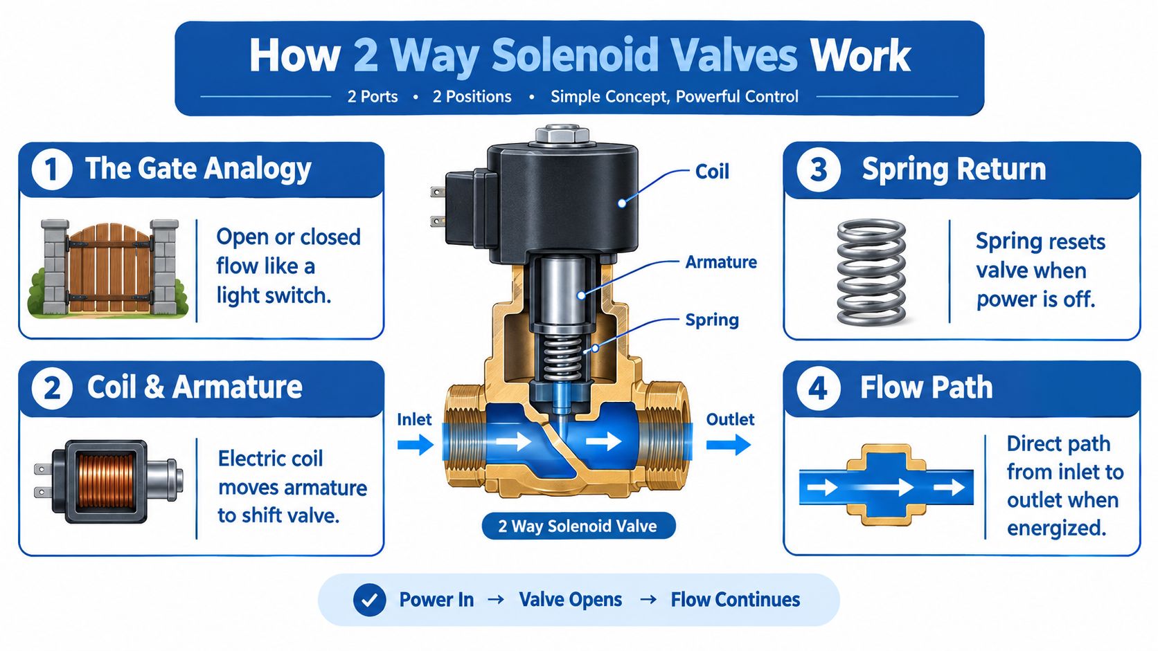
Most 2/2 valves used for safety isolation are normally closed. With the coil de-energised, a spring pushes the armature, plunger or poppet onto its seat, stopping flow. Apply the correct voltage and current flows through the coil. The coil produces a magnetic field, pulling the armature away from the seat and opening the passage. Remove power and the spring returns the valve to its closed state.
A normally open design works in the opposite way, but it must be selected deliberately. The safe state depends on the machine function. A valve that must stop flow after a power loss will usually need normally closed operation, while a valve that must maintain flow without electrical power may need normally open construction.
Direct-acting and servo-assisted operation
A direct-acting valve uses the electromagnetic force to move the sealing element itself. It can operate without a minimum differential pressure, which suits low-pressure, vacuum and small-flow applications. The trade-off is that a compact direct-acting valve may have a more limited flow capacity.
A servo-assisted diaphragm valve uses pressure differential to help open the main passage. The coil first opens a small pilot orifice, allowing pressure above the diaphragm to change. The diaphragm then lifts and permits the larger flow path to open. This design can offer higher flow through a relatively compact body, but it needs suitable differential pressure and cleaner media.
The coil, armature, spring and seal must work as one assembly. A correctly energised coil won't open a valve if contamination holds the armature, the pressure force exceeds the available magnetic force, or the seal has swollen in incompatible fluid.
Key concept: Electrical power commands the valve, but pressure differential, cleanliness, spring force and seal condition determine whether the valve can complete the movement.
For applications that need flow switching rather than simple isolation, compare the arrangement with a 3-way solenoid valve. A 2 way valve has one flow path. A 3-way valve provides another route for switching or exhaust.
The operating sequence is shown in this embedded video. Check that the player retains its intended frame and 16:9 aspect ratio when it's placed into the page.
Valve Types Materials and Construction Choices That Matter
The fluid determines much of the valve design. A body and seal combination that works well with clean compressed air may be unsuitable for hot oil, treated water, steam or a hazardous gas installation. Procurement should therefore start with the media, temperature and pressure conditions, not with the cheapest familiar part number.
Body materials and seals
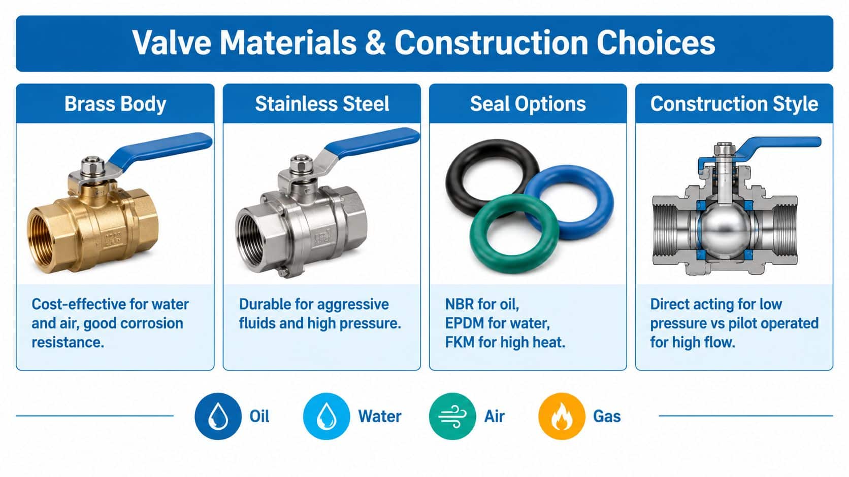
Brass is widely used for general water, air and utility duties. It can provide a practical balance of cost, machinability and corrosion resistance in ordinary installations. Stainless steel is the stronger choice where the media, washdown environment or contamination risk demands greater resistance. UK miniature solenoid valve market commentary identified stainless steel as the largest material segment, with a 48.48% revenue share in 2024, and placed UK market revenue at USD 62.7 million in 2024, projected to reach USD 86.9 million by 2030 at a 5.6% CAGR from 2025 to 2030. The source also reported that the UK represented 3.4% of global revenue in 2024. These figures appear in the UK miniature solenoid valve market outlook.
Those are USD market values, not UK purchase prices. For a UK quotation, ask for the supplier's current GBP price rather than converting a market forecast into a product cost. The material decision should follow compatibility and service conditions, not the headline price.
Seal selection is equally important:
- NBR is commonly considered for mineral oil and general hydraulic duties, subject to the supplier's compatibility chart.
- EPDM is often chosen for water-based applications, but it isn't suitable for every oil.
- FKM can suit higher-temperature or chemically demanding service, provided the specific fluid and temperature are approved.
The correct seal depends on the actual fluid, additives, temperature and duty cycle. A familiar elastomer isn't automatically safe for a different formulation.
Construction and compliance
Direct-acting construction is useful where the valve must open with little or no differential pressure. Servo-assisted diaphragm construction can provide higher flow, but it depends on pressure differential and is more sensitive to blocked pilot passages or dirty media.
UK suppliers list 2-way valves in brass and stainless-steel bodies, with pressure ranges reaching 100 bar and compatibility with gases and liquids, as shown in this UK solenoid valve range. Treat that as a catalogue range, not permission to apply every valve at the maximum pressure. The individual datasheet still controls the allowable pressure for the selected body, seal, temperature and media.
For gas safety, potable water, or hazardous-area work, confirm the relevant approval and installation requirements. ATEX and intrinsically safe variants may be necessary in hazardous zones, while a standard coil may be unacceptable. A design engineer should also check whether the valve's fail position, enclosure, connector and temperature class match the complete installation.
For port geometry, UK suppliers commonly use BSPP threads, marked with the letter G. Thread size is stated in inches, even when the rest of the machine specification uses metric units. One example lists a 2 in BSP thread, a 2.309 mm pitch and a 59.614 mm outer diameter, as explained in this BSP thread selection guide. Don't identify a replacement by nominal thread size alone. Check sealing method, pitch, outside diameter and port orientation.
For a wider comparison of hydraulic construction, use the hydraulic valve types guide.
Electrical and Hydraulic Specifications You Must Get Right
A datasheet gives you the boundaries within which the valve can work. The job is to connect each figure to the machine's real operating conditions.
Voltage comes first. A UK catalogue example lists 24 V DC for a 2-port, normally closed valve with G-threaded inlet and outlet ports, as shown by this 24 V DC solenoid valve listing. Confirm whether the control circuit supplies AC or DC, measure voltage at the coil terminals under load, and check the connector pin arrangement. A nominal 24 V supply can fall at the valve because of cable length, undersized conductors, a poor earth or a failing relay.
A DIN connector is common on many UK solenoid-valve assemblies. An IP65 rating means the enclosure is dust-tight and protected against water jets from any direction, according to this DIN connector and ingress protection explanation. The rating only applies when the connector, gasket, cable entry and cover are correctly assembled. A damaged seal or loose cable gland can defeat the protection.
Reading hydraulic capacity
Flow and pressure need to be considered together. A larger port doesn't guarantee adequate flow, and a high pressure rating doesn't tell you how much pressure drop the valve creates at the required flow.
The following UK-supplied hydraulic examples show the difference between a higher-flow body and a compact lower-leakage cartridge.
| Specification | 115 l/min Cartridge | 55 l/min Cartridge |
|---|---|---|
| Nominal flow | 115 l/min | 55 l/min |
| Maximum pressure | 240 bar | 240 bar |
| Internal leakage | 0 to 0.50 cc/min at 210 bar | 0 to 0.25 cc/min at 240 bar |
| Filtration | ISO 18/16/13 | Not stated in the supplied specification |
| Operating temperature | -40 to 120°C | Not stated in the supplied specification |
| Cartridge mass | Not stated in the supplied specification | 0.12 kg |
The 115 l/min model also accepts a viscosity range of 3 to 640 cSt, which helps it cover cold-start and hot-running conditions when the fluid remains within the manufacturer's limits. Its specification calls for ISO 18/16/13 filtration, making cleanliness a direct part of valve reliability. The full values are provided in this CETOP 2 solenoid valve specification.
The 55 l/min cartridge has lower nominal flow, internal leakage of 0 to 0.25 cc/min at 240 bar, and a cartridge mass of 0.12 kg, according to this compact 2-position hydraulic solenoid valve specification. Its compact form and leakage figure don't make it universally better. If the circuit needs more flow, undersizing raises pressure drop and heat. Oversizing can add package volume and cost without improving control.
Installation dimensions
Use the thread information as a mechanical check, not as the complete selection method. A valve with the correct G-thread may still have the wrong coil voltage, flow capacity, seal, pressure rating or fail position.
Check the datasheet for:
- Flow capacity: Match the valve to actual circuit demand and acceptable pressure drop.
- Maximum pressure: Include pressure spikes, not only normal gauge readings.
- Leakage: Confirm the permitted leakage at the stated pressure and temperature.
- Filtration: Maintain the specified cleanliness level and protect pilot passages.
- Temperature: Include ambient temperature, fluid temperature and coil heat.
- Connector protection: Keep the DIN connector and gasket correctly fitted.
Where 2 Way Solenoid Valves Excel in Mobile and Industrial Applications
A 2 way valve earns its place where the circuit needs dependable isolation rather than complex directional routing. In a mobile power pack, it can enable a hydraulic function, isolate an accumulator branch or control a release path. In materials handling equipment, it may manage a clamp, stabiliser or auxiliary circuit. In manufacturing, it can control oil, water, air or another approved medium at a process point.
The valve's behaviour changes with the circuit around it. A load-holding application prioritises low leakage and correct fail-state behaviour. A high-flow power-pack circuit prioritises capacity, pressure drop and heat management. A utility water application may place greater emphasis on body material, seal compatibility and contamination tolerance.
Mobile machinery
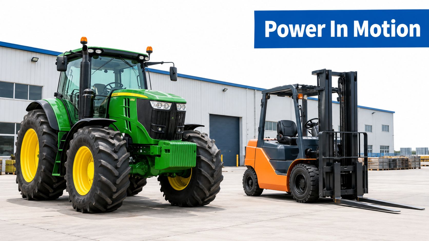
Agricultural machinery works outdoors, where moisture, dirt, vibration and temperature changes challenge connectors and seals. A valve selected for a clean indoor test rig may struggle if filtration is neglected or the electrical connection isn't protected.
A compact valve can suit a space-limited manifold, but compactness doesn't replace hydraulic sizing. The 55 l/min and 115 l/min examples show why the designer must start with flow demand, pressure and leakage rather than choose by body appearance.
Industrial equipment
Industrial systems often run predictable cycles, which makes duty-cycle analysis possible. A valve that opens briefly and then returns closed has different coil-heating requirements from one that remains energised throughout a production shift. The same nominal valve can therefore have very different lifetime costs in two machines.
UK miniature solenoid valve demand remains commercially significant. The market outlook cited earlier connects compact formats with automation, fluid control and equipment maintenance, while stainless steel's reported share points to the importance of corrosion resistance and material selection.
Replacement procurement
UK buyers commonly need a replacement quickly. Import-led supply chains, stocked distributors and cross-reference work all matter when a line is stopped. Before ordering, record the old valve's port thread, coil voltage, connector, normal state, body material, seal and markings. Then compare the complete operating envelope, not just the catalogue description “2-way normally closed”.
A replacement that fits the manifold but has a different leakage limit or minimum pressure requirement can create a new fault. For MRO teams, keeping the datasheet with the machine record is as important as keeping the part number.
How to Select the Right 2 Way Solenoid Valve for Your Circuit
Selection should follow the circuit sequence, not the supplier's product list. Start at the fluid and finish at lifetime operating cost.
-
Define the media. Identify whether the valve will handle hydraulic oil, water, compressed air, gas, steam or another fluid. Confirm body and seal compatibility at the actual temperature.
-
Measure the hydraulic demand. Record normal flow, peak flow, working pressure and any pressure spikes. Select by circuit demand, not port size alone. The wrong flow capacity can create pressure drop and heat, even when the thread appears correct.
-
Choose the normal state. Normally closed means the valve stays shut without power. Normally open means it stays open without power. Choose the state that gives the required machine response after a power loss or control fault.
-
Check the pressure principle. Direct-acting construction suits applications with low or zero differential pressure. Servo-assisted construction can support higher flow, but it needs enough differential pressure and cleaner media.
-
Review duty cycle. Ask how often the valve switches and how long the coil remains energised. Continuous energisation can generate heat, especially in a compact enclosure. Check the manufacturer's coil and ambient-temperature limits.
Latching versus conventional coils
A conventional spring-loaded valve draws power while it remains open. A UK supplier reports that a magnetically latched valve can use less than 1 joule to activate and remain switched on, compared with around 5.5 W to open and about 0.35 W to hold a conventional spring-loaded valve. The comparison is described in this UK guidance on magnetically latched solenoid valves.
That makes latching or bistable construction worth considering for low-duty or hold-open applications, particularly where battery capacity, enclosure heat or energy efficiency matters. It won't suit every safety function. A spring-return valve may be preferable when the machine must return to a defined state after power is removed.
| Circuit condition | Initial direction |
|---|---|
| Little or no differential pressure | Investigate direct-acting construction |
| Higher flow with adequate differential pressure | Investigate servo-assisted construction |
| Dirty or contamination-prone media | Prioritise filtration and pilot-passage tolerance |
| Long hold-open periods | Compare latching energy use with conventional coil heating |
| Safety isolation on power loss | Check normally closed spring-return behaviour |
Ask for a current GBP quotation for the complete valve, coil and connector. A higher purchase price can be sensible if it reduces coil heat, service frequency or replacement risk, but the calculation must use the actual duty cycle and maintenance conditions.
Installation Troubleshooting and Next Steps with MA Hydraulics
Install the valve in the orientation specified by its manufacturer. Confirm the inlet and outlet markings, flow arrow and access for coil removal before tightening pipework. For BSPP connections, use the specified sealing arrangement rather than assuming the thread itself seals the joint.
Check the electrical side before removing the valve. Measure voltage at the coil while it's commanded on, inspect the DIN connector pins, and confirm that the connector gasket and cable entry preserve its stated IP65 protection. A coil that receives insufficient voltage may click weakly or remain shut, while a coil energised continuously beyond its rating may overheat.
Hydraulic faults often start with contamination. Maintain the required filtration level, inspect the filter condition and flush debris from new or repaired pipework. If the valve leaks internally, check the seat, poppet or diaphragm, fluid compatibility, pressure differential and contamination. If it won't open, check the normal state, coil resistance, voltage, armature movement and whether a servo-assisted design has the required differential pressure.
Use the inline valve installation guidance alongside the manufacturer's datasheet. During final quality control, check that embedded videos retain their intended frames and that any wording within supplied images is accurate and legible. Those details matter when technicians use the page as a service reference.
A practical specification record should include the valve function, media, flow, pressure, temperature, leakage requirement, filtration, coil voltage, connector, thread, normal state and duty cycle. That record makes future cross-referencing faster and reduces the risk of fitting a visually similar but technically unsuitable replacement.
MA Hydraulics Ltd can help UK OEMs and maintenance teams select solenoid valves, hydraulic inline components and bespoke power-pack assemblies for mobile and industrial circuits. Phone 01724 279508 today for application advice and cross-references, or send your requirements through MA Hydraulics Ltd for support with component selection and system builds.
