
You're on a weekend shift at a UK plant when the control system shows a valve that should be open, but flow is still restricted. Walking to the valve means time, access equipment and a manual intervention. An actuator ball valve removes that delay by combining a quarter-turn ball valve with a powered actuator, allowing the assembly to operate locally, remotely or automatically.
The difficult part isn't turning the ball through 90 degrees. It's specifying the complete package so the actuator has enough torque, the mounting interface is correct, the control signal matches the site and the valve remains maintainable after installation. This guide takes the view of a UK hydraulics engineer checking the valve, actuator, controls and operating conditions as one system.
What an Actuator Ball Valve Actually Does
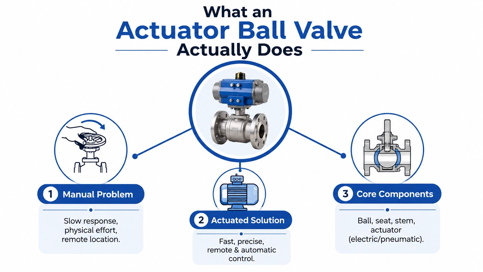
A manual ball valve uses a handle to rotate a drilled ball inside the valve body. Turn the ball through 90 degrees and the bore aligns with the pipe, allowing flow. Turn it back and the solid side of the ball blocks the passage. An actuator performs that same quarter-turn mechanically, using an electric motor, compressed air or hydraulic power.
A typical package contains a full-bore or reduced-port ball valve, a stem, seats, an actuator and a mounting connection. For petroleum, petrochemical and allied industries, BS EN ISO 17292:2015 covers metal ball valves from DN 8 through DN 600, providing a useful reference for the range of industrial line sizes available (BS EN ISO 17292:2015 size scope). The actuator may also include limit switches, a position indicator, feedback instrumentation and a manual override.
Why the two components belong together
The actuator isn't selected from valve size alone. Opening torque changes with seat material, pressure, temperature, stem seals and the condition of the fluid. A clean-water valve with a PTFE seat may behave very differently from a valve handling slurry, scale-forming water or viscous oil.
That's why a buyer should ask for the valve torque data and actuator output data together. The actuator must exceed the valve's worst-case breakaway and running torque, with a suitable engineering margin. The exact margin depends on the manufacturer's method, service and approval requirements, so it should be confirmed rather than assumed.
Practical rule: Size from the hardest opening condition, not from the torque needed once the ball is already moving.
UK actuator work sits within a formal standards environment. BSI committee PSE/18 provides UK input into CEN/TC 69 and ISO/TC 153 working groups covering the design, manufacture, installation and testing of valve actuators (BSI PSE/18 committee responsibilities). The mounting interface also matters. ISO 5211 pads allow compatible electric or pneumatic actuators to mount directly, avoiding unnecessary brackets and reducing alignment errors, while UK RS documentation identifies ISO 5211 compatibility and WRAS approval on a brass ball valve platform (UK RS ISO 5211 and WRAS ball valve documentation).
For projects linking valves to wider plant data, a strategic guide to factory AI can help engineers think beyond the valve itself and consider how operating data may support alarms, diagnostics and maintenance decisions. For flow diversion specifically, a 3-way ball valve installation uses the same basic actuator principle, rotating the ball to change the flow path.
Electric Pneumatic and Hydraulic Actuators Compared
The right actuator depends on the job, not on a universal ranking. Electric, pneumatic and hydraulic units can all operate a quarter-turn ball valve, but they differ in available infrastructure, response, control precision, failure behaviour and maintenance burden.
| Parameter | Electric, 24 VDC / 230 VAC | Pneumatic, 6 bar | Hydraulic, 70–210 bar |
|---|---|---|---|
| Best fit | Remote sites, precise control and integrated automation | Rapid on/off operation where compressed air is available | High torque and demanding mobile or pipeline duty |
| Site requirement | Electrical supply and suitable control wiring | Compressor, receiver, filtration, regulation and distribution | Hydraulic power unit or existing hydraulic circuit |
| Typical control character | Good position control and feedback integration | Fast quarter-turn switching | High force in compact packages |
| Main limitation | Electrical supply, duty cycle and enclosure selection | Air quality, leakage and compressor dependence | Power-unit complexity and hydraulic cleanliness |
| Safety choice | Spring return, battery backup or stay put, depending on design | Spring return or double acting with stored air | Spring return, accumulator support or stay put |
Electric actuators suit sites where the control system needs position feedback, precise movement or straightforward integration with a PLC. They can work well at remote locations where there is no compressed-air ring main, although the designer must check voltage, enclosure protection, ambient conditions and duty rating. A small electric actuator may also be unsuitable for repeated cycling if its S2 or S4 duty classification doesn't match the operating pattern.
Pneumatic actuators remain attractive for fast isolation. A UK supplier datasheet gives a 5-second travel time, 2 Nm actuator torque, 100,000-cycle duty, IP67 enclosure and a 0–10 bar pressure range for a 3/4 in actuated WRAS ball valve (UK actuated WRAS ball valve datasheet). Those figures describe one supplied package, not every pneumatic or electric valve, but they show why buyers should read the complete datasheet rather than rely on a generic actuator label.
Pneumatic systems need clean, regulated air. Moisture, contaminated filters, pressure drops and leaking tubing can make an actuator slow or unreliable. The plant may also need to maintain the compressor and air network, so the actuator's purchase price isn't the whole cost.
Hydraulic actuation earns its place where torque is high or a hydraulic circuit already exists. UK hydraulic actuator guidance identifies quarter-turn applications including ball, butterfly and plug valves, plus dampers, and lists ISO 5211 mounting patterns from F05 through F40 (UK hydraulic actuator quarter-turn applications). Hydraulic systems can deliver substantial force in compact equipment, but oil cleanliness, filtration, hose routing and leak control become central design concerns.
If the site already has reliable air, pneumatic may be the simplest fast-acting option. If it has electrical control but no air, electric often creates fewer support requirements. If torque and compact force dominate, hydraulic deserves serious consideration.
ISO 5211 Mounting and Torque Sizing
ISO 5211 is a mechanical interface standard, not a guarantee that every actuator will fit every valve. The flange pattern, bolt circle, drive square or double-D insert and maximum transmitted torque must all match. A compliant actuator can bolt directly to a compliant valve when the selected sizes agree, which reduces the need for custom brackets and helps keep the stem and actuator axes aligned.
Common flange designations include F03, F04, F05, F07, F10 and F12. Do not select from the flange name alone. Confirm the valve manufacturer's drawing, the actuator's mounting table and the drive insert dimensions before ordering.
| ISO 5211 flange | Bolt circle | Drive square | Typical ball valve size | Torque range |
|---|---|---|---|---|
| F03 | Manufacturer to confirm | Manufacturer to confirm | Small-bore service | Valve datasheet required |
| F04 | Manufacturer to confirm | Manufacturer to confirm | Small-bore service | Valve datasheet required |
| F05 | Manufacturer to confirm | Manufacturer to confirm | Small to medium service | Valve datasheet required |
| F07 | Manufacturer to confirm | Manufacturer to confirm | Medium service | Valve datasheet required |
| F10 | Manufacturer to confirm | Manufacturer to confirm | Medium to larger service | Valve datasheet required |
| F12 | Manufacturer to confirm | Manufacturer to confirm | Larger industrial service | Valve datasheet required |
The table deliberately leaves dimensions to the certified drawing. ISO 5211 flange dimensions and drive sizes must not be guessed, because manufacturers may provide different combinations within a product family.
Read torque from the operating condition
Start with breakaway torque, then check running and seating torque. Pressure differential can increase the force required to start the ball moving. A UK torque table gives a 2 in clean-service valve a requirement of about 32 Nm at 0 barg and up to 54 Nm at 19 barg. In slurry or dry service, the same table shows torque rising to 70 Nm at 19 barg (UK ball valve actuation torque figures).
Those figures explain why nominal line pressure isn't enough. Seat friction, solids, deposits and temperature may dominate the opening event. Select the actuator against the highest credible torque and then confirm the supplier's recommended margin for that specific valve.
A worked example must use verified valve data. If a 2 in PN16 stainless ball valve has a published breakaway torque near 76 Nm at its specified operating condition, an engineer may apply the manufacturer's stated service factor and select an actuator with output above the resulting requirement. A quoted 120 Nm pneumatic actuator might be suitable only after the actual torque curve, pressure, seat material and air supply have been checked. Without that valve-specific figure, a precise result would be unsafe to claim.
For installation planning, follow the supplier's instructions on inline valve installation and verify that pipework loads aren't being transferred into the valve body or actuator mounting.
Control Modes and Fail-Safe Options
A simple isolation valve usually needs only two positions, open or closed. A process control valve may need the ball to stop at intermediate positions, with the actuator receiving a signal that represents the required opening. The control mode determines the actuator electronics, feedback equipment and commissioning method.
| Control mode | Signal type | Fail-safe action | Best use case |
|---|---|---|---|
| On/off | Switched supply or solenoid command | Spring close, spring open or stay put | Isolation, sequencing and interlocks |
| Modulating | 4–20 mA or 0–10 V | Defined safe position or last position | Flow, pressure or temperature control |
| Networked modulating | 4–20 mA with HART or Profibus | Site-specific safe state | Diagnostics and integrated plant control |
| Hydraulic quarter turn | Hydraulic command and feedback | Accumulator, spring return or stay put | Mobile equipment and high-torque service |
A 4–20 mA signal remains common for modulating control because the control system can distinguish a live low signal from a broken circuit. A 0–10 V input can also command position, but the designer must consider cable runs, electrical noise and the capabilities of the existing controller. HART or Profibus can be worthwhile where diagnostics, configuration and status information justify the additional equipment and integration effort.
Choose the failure response first
Ask what the process must do when each energy or signal source disappears.
- Power failure: A spring-return electric design may drive to a defined position, while a battery-backed or mechanically supported package may provide another response.
- Signal loss: The positioner can be configured to close, open or remain at its last valid position, subject to the control system and actuator design.
- Air failure: A spring-return pneumatic actuator can move to its specified safe position. A double-acting unit generally needs stored air or another backup arrangement if it must move after supply loss.
- Hydraulic failure: An accumulator or spring-return arrangement may provide emergency movement, but the circuit must be designed and tested for that duty.
A stay-put actuator is appropriate where sudden movement would create a greater hazard than holding the current position. Firewater, chemical dosing, cooling and fuel systems may require different responses, so the safe state must come from the process risk assessment, not a catalogue default.
For a hydraulic control arrangement, a hydraulic valve controller may form part of the wider system, but its signal, pressure and failure behaviour still need to be matched to the actuator and valve assembly.
Real UK Applications and Integration Examples
An actuator ball valve becomes easier to specify when the application is described as a sequence of events rather than a product name. What must open, what must close, how quickly must it move, and what should happen after a supply failure?
At a wastewater treatment works operated by a large UK water company, an electric modulating ball valve could control a chemical dosing line. The process engineer would specify the valve materials and pressure class, then require a 4–20 mA position signal back to the PLC. The actuator would need controlled movement, position feedback and an enclosure suitable for the installation environment. The safe state would depend on the chemical and dosing sequence, so it shouldn't be assumed without a process review.
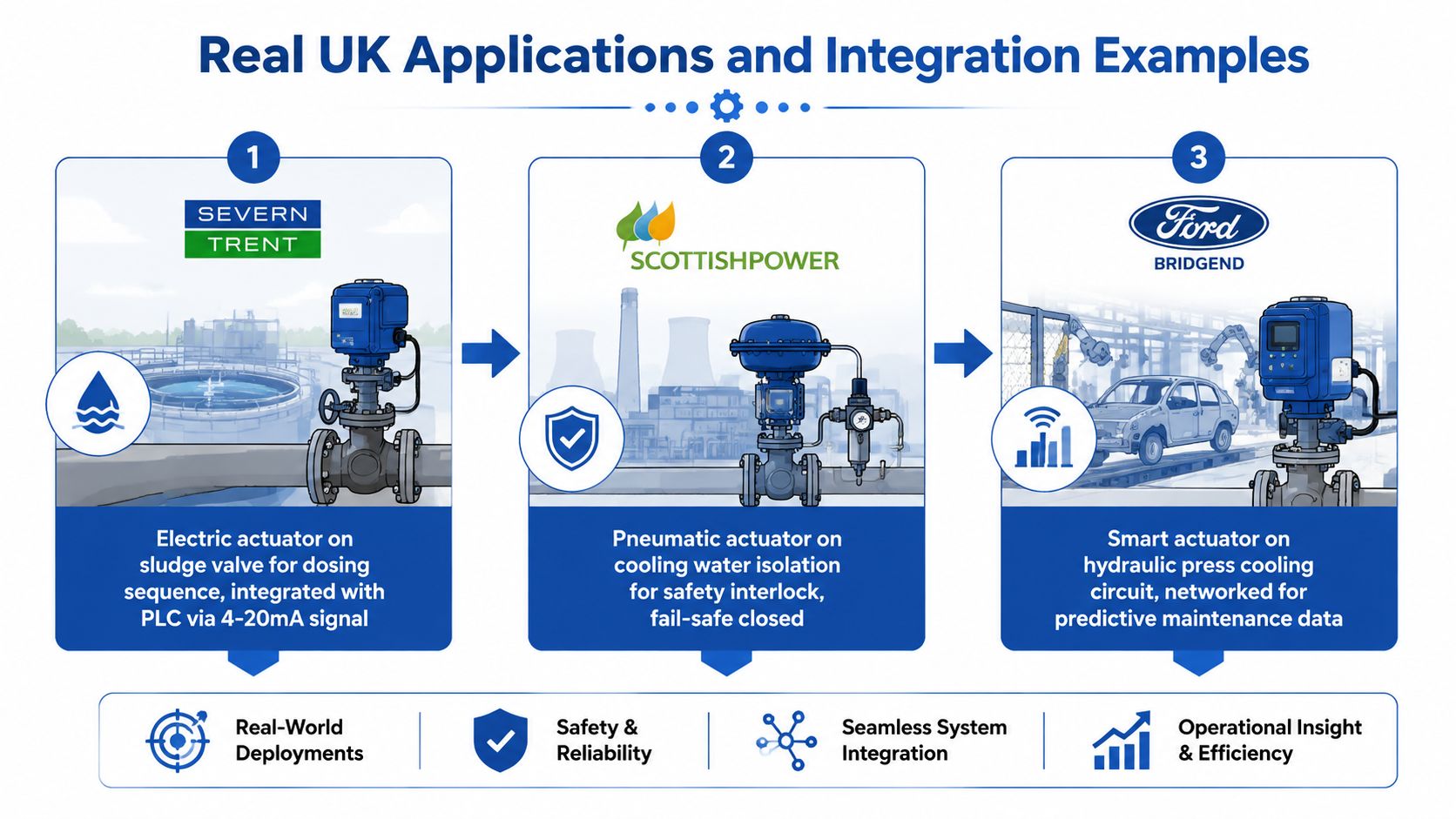
A Midlands automotive component supplier presents a different case. The factory has a 6 bar compressed-air ring, making double-acting pneumatic ball valves practical at machine drops. A NAMUR-mounted solenoid pilot can command each actuator, while local position switches confirm open and closed states. If the valve isolates a machine during a safety event, the designer may choose spring return or stored-air backup, depending on the machinery risk assessment and required safe position.
A quarry mobile plant circuit has another set of priorities. A hydraulic actuator ball valve can control water spray suppression around a crusher where electrical cabling may be vulnerable and an existing hydraulic supply is available. The engineer would check hydraulic pressure, available flow, contamination control, hose protection, valve torque and the required response after hydraulic loss. A stay-put or spring-return arrangement may be appropriate, but only after deciding whether continued spray or isolation is safer.
The mounting flange must be confirmed in all three cases. A package that fits the valve stem but uses the wrong bolt pattern or drive insert can create alignment problems, excessive side loading and premature wear.
The following video can support a visual explanation of quarter-turn actuator operation. Check the embedded frame in the page preview to ensure it renders at the intended aspect ratio.
Maintenance and Common Failure Points
Maintenance starts at the valve and stem interface, not at the actuator cover. A manual from APV describes recurring requirements such as leak checks, depressurisation before service, seal replacement and inspection of mounting parts, instrumentation and seals (APV ball valve maintenance manual). Even when an actuator is marketed as maintenance-free, the complete assembly still needs condition checks.
Inspect the complete mechanical path
Before removing a cover or loosening a connection, isolate and depressurise the line. Confirm that electrical, pneumatic and hydraulic energy has been made safe, then inspect:
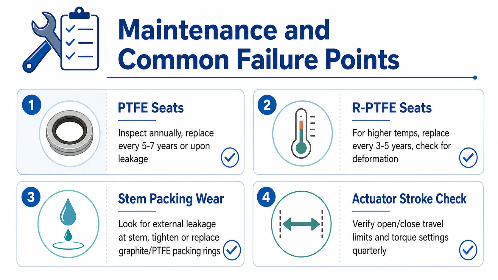
- Stem packing: Look for dampness, residue or visible leakage around the stem. A slight adjustment may help, but damaged packing needs replacement.
- Seats and seals: PTFE, reinforced PTFE, elastomer and other seat materials respond differently to temperature, chemicals and cycling. Replace them when leakage, deformation or material damage appears.
- Drive insert: Check the ISO 5211 insert and stem connection for rounding, fretting and impact marks. A damaged insert can transmit less torque even when the actuator itself operates correctly.
- Mounting hardware: Check bolts, brackets, couplings and alignment. Loose or misaligned parts can turn normal actuator torque into damaging side loads.
- Feedback components: Test limit switches, positioners and transmitters. Moisture ingress may cause drift or intermittent signals before the valve visibly fails.
Pneumatic systems need attention to filtration, regulation, water removal and leakage. Poor air quality or an undersized supply can make the valve appear sluggish, particularly during breakaway. Hydraulic packages need clean oil and effective filtration, while electric actuators benefit from duty-cycle records, terminal inspections and checks of contactors or control components.
A slow valve isn't automatically a faulty actuator. Check supply pressure, filters, tubing, alignment, seat condition and torque demand before replacing the actuator.
Cheap installations often fail at the interface. An actuator may have sufficient catalogue torque, yet the drive insert can deform if the valve's actual breakaway demand exceeds the selected margin. Position feedback can also drift because of moisture, loose couplings or incorrect travel-limit settings. Record the symptoms, the process condition and the supply readings before changing parts.
Choosing the Right Package and Getting Support
Start the purchase with an application sheet, not a part number. Record the fluid, temperature, pressure class, line size, flow direction, cycling pattern, required safe position, available power and control signal. Then ask the supplier to match the valve, actuator, mounting interface and accessories as one package.
A useful UK specification check includes:
- Valve standard: Confirm whether the valve is specified to BS EN ISO 17292:2015 or another relevant product standard.
- Mounting: Confirm the ISO 5211 flange, drive insert and coupling dimensions from drawings.
- Pressure equipment: Check the applicable PED 2014/68/EU conformity route for the equipment and application.
- Site approval: Confirm ATEX requirements for hazardous areas and WRAS approval where potable-water duty requires it.
- Actuator data: Request output torque, duty rating, enclosure rating, ambient limits, supply details and manual override arrangements.
- Evidence: Ask for torque verification, test documentation, wiring diagrams, installation instructions and recommended spares.
Standards can change, so don't rely on an old description of “a standard ball valve”. Industry commentary identifies EN 1983:2013 for steel ball valves and EN 13547:2013 for copper alloy ball valves as harmonised standards under EU Directive 2014/68/EU, while CEN TC69 policy has moved towards a product standard covering different materials (European ball valve standards commentary). The current conformity position should be checked for the project date and equipment category.
The same 2 in valve can be quoted as a basic on/off electric package, a spring-return pneumatic package with position feedback, or a hydraulic package for a mobile circuit. Those aren't interchangeable offers. They carry different infrastructure, controls, maintenance and failure-response requirements.
MA Hydraulics Ltd can help with hydraulic components, valve selection and bespoke power solutions for mobile and industrial systems, including hydraulic actuator arrangements where the site already has a suitable circuit. Ask for the technical datasheet, torque verification certificate, spare-parts recommendation and confirmation of ATEX or WRAS requirements before placing the order.
MA Hydraulics Ltd can help you match an actuator ball valve package to the required torque, hydraulic circuit, control method and safe-state response. Visit MA Hydraulics Ltd, phone 01724 279508 today, or send a message for technical guidance, datasheets and spares support.
