
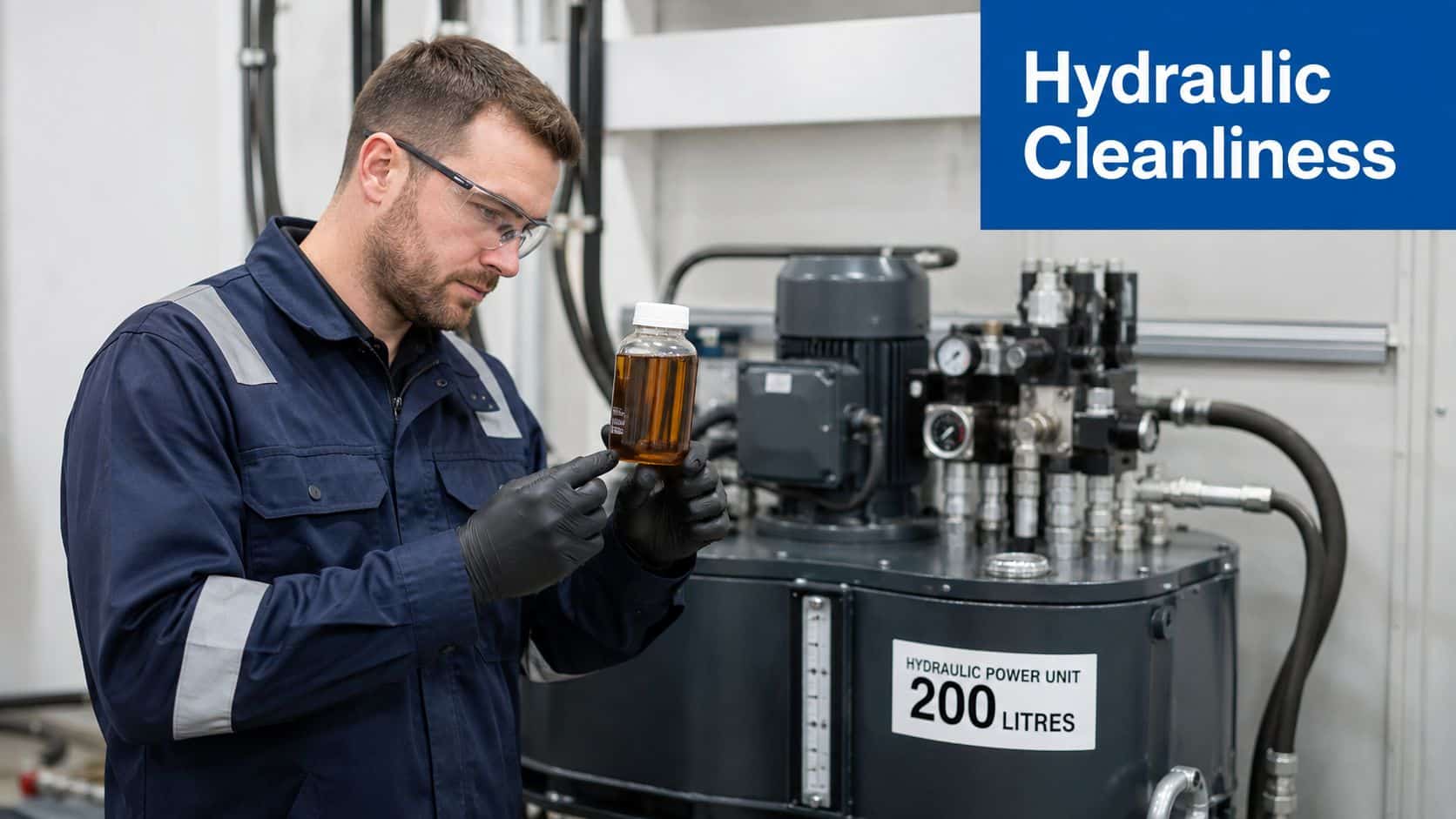
A maintenance engineer draws an oil sample from a 200-litre hydraulic power unit after another bout of erratic servo-valve behaviour. The laboratory result returns ISO 22/20/17, well above the 18/16/13 cleanliness target expected downstream of precision valves. The unit already has pressure and return-line filters, yet contamination continues to build.
That situation is common in UK mobile and industrial hydraulics. Standard filters still matter, but they work within the main circuit's operating conditions. They don't necessarily provide the repeated, independent oil conditioning needed when a machine spends long periods idle, operates in dusty surroundings, or contains expensive components that can't tolerate fine silt.
Kidney loop filtration adds a separate bypass circuit. A low-flow pump draws oil from the reservoir, passes it through dedicated filter media, and returns the conditioned oil to the tank while the main machine remains available for production or maintenance. The economic question isn't whether the technology works. It's whether the avoided failures, oil changes and downtime justify the equipment on your particular reservoir or gearbox.
Why Hydraulic Cleanliness Demands More Than In-Line Filters
In-line filters are essential protection, but they aren't a complete fluid-management strategy. A pressure-line element protects downstream components, while a return-line element catches contamination before oil reaches the reservoir. Both are exposed to the system flow only when the main pump and actuators are operating.
That creates two practical limitations. First, high-flow filtration has to process the oil quickly, so the element selection is governed by pressure drop, flow capacity and dirt-holding requirements rather than leisurely polishing. Secondly, contamination can enter or settle during standby, maintenance, hose changes and reservoir breathing. A filter that isn't circulating oil cannot remove what reaches the tank while the machine is idle.
A kidney loop works alongside, rather than instead of, the existing inline hydraulic oil filter. Its pump and element are sized for a separate low-flow circuit, which lets the unit condition the reservoir without taking the main hydraulic circuit out of service.
The practical difference in duty
A bypass loop repeatedly processes the same oil. Each pass removes a portion of suspended contamination, so the reservoir gradually becomes cleaner instead of relying on one pass through a high-flow filter during an operating cycle.
Practical rule: If a contamination problem is present while the machine is stationary, the main circuit can't be the only cleaning method.
This is particularly relevant where a servo valve, proportional valve, axial piston pump or gearbox carries a high replacement cost. It also matters where access is difficult, a failed component causes a production interruption, or oil disposal involves more than the purchase price of fresh fluid.
The case is weaker on a small, lightly loaded circuit with modest cleanliness requirements, low downtime exposure and simple components. In that situation, better breathers, correct in-line filtration, disciplined sampling and good maintenance practice may solve the problem at lower cost. Kidney loop filtration earns its place when fluid cleanliness is a reliability control, not merely a housekeeping preference.
How Kidney Loop Filtration Works in Practice
The arrangement is straightforward, but the details determine whether it delivers useful conditioning.
-
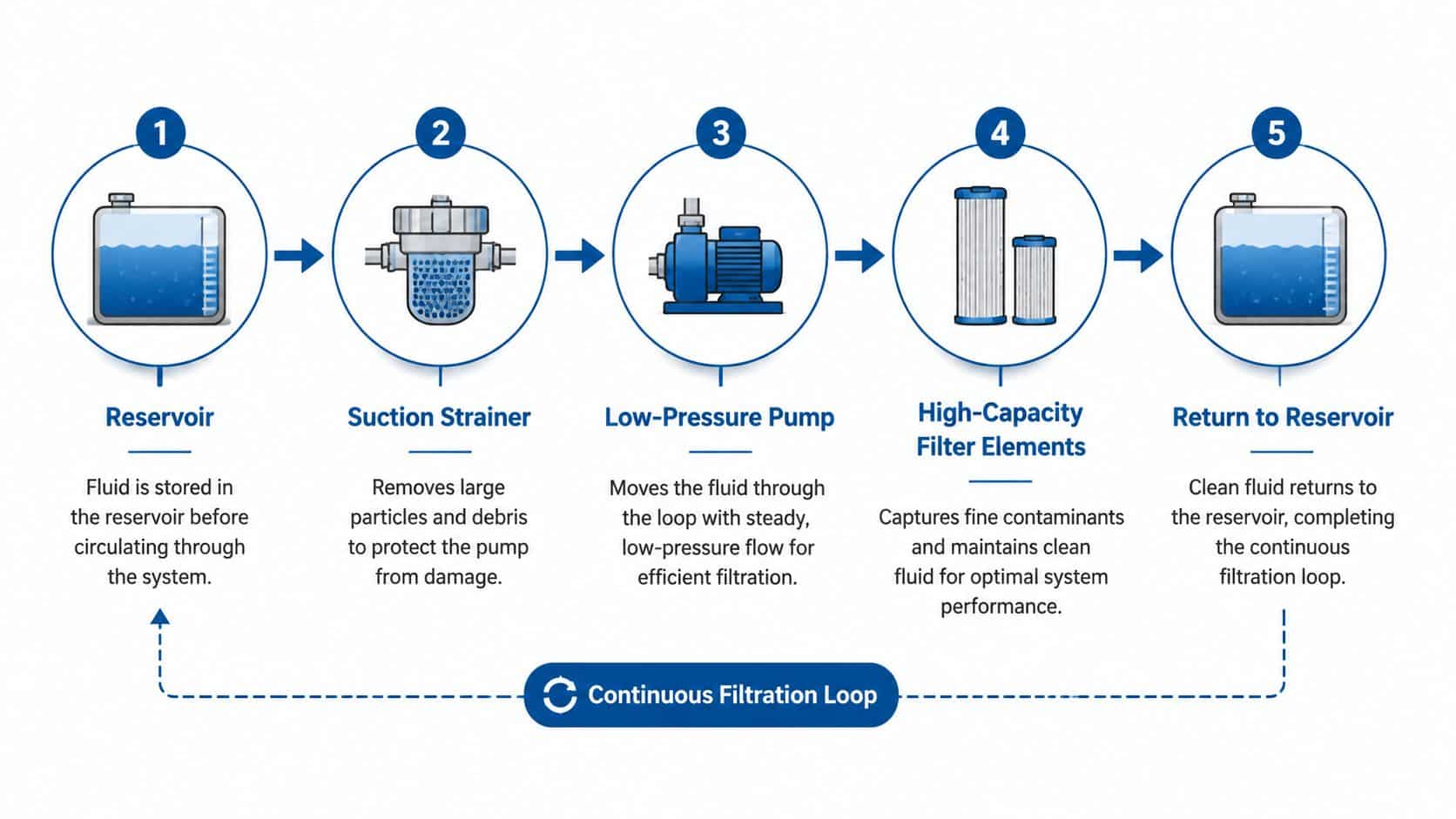
Reservoir draw-off. A dedicated suction connection takes oil from a suitable point in the tank. The pickup should avoid settled sludge while remaining submerged through the full operating range.
-
Suction protection. A coarse strainer protects the low-pressure pump from larger debris. It must create minimal restriction because a bypass pump starved on its inlet will cavitate, run noisily and lose useful flow.
-
Low-pressure circulation. The pump moves oil through the separate circuit. It doesn't need to supply actuator pressure, so the circuit can be designed around steady conditioning flow rather than peak machine demand.
-
Fine filtration. One or more elements remove suspended particles. UK industry coverage commonly contrasts mainstream machine filters of about 10 to 30 microns with kidney-loop filtration capable of capturing roughly 3 to 7 micron particles. The comparison is described in this industry explanation of kidney-loop filtration.
-
Return to tank. Cleaned oil goes back to the reservoir, where it mixes with the remaining fluid and enters the loop again.
Fixed circuits and portable carts
A permanent installation normally uses its own motor-pump group, filter housing, isolation valves, gauges and return plumbing. That arrangement suits a power unit that needs regular or continuous conditioning and can accommodate a safe, accessible skid.
A portable filter cart is more flexible. Engineers can wheel it between reservoirs, connect it during planned maintenance or use it to polish oil without modifying every machine. The trade-off is labour, connection control and the risk that the cart isn't available when contamination appears.
Particle removal is only one part of fluid conditioning. If water ingress is a known problem, specify a coalescing stage or vacuum dehydration equipment rather than assuming a particulate element will remove dissolved or emulsified water. UK filtration suppliers describe kidney-loop circuits as separate, offline systems used where in-line filtration cannot achieve the required cleanliness or where water ingress needs attention, as outlined by Kleenoil's overview of offline filtration.
The loop's name is useful because it conveys the principle, not because it implies a particular pump, element or flow rate. The correct design depends on oil viscosity, reservoir volume, contamination type, allowable pressure and the cleanliness code demanded by the components.
Measurable Benefits for Hydraulic System Longevity
Cleaner oil reduces the abrasive and erosive load placed on pumps, valves and precision control components. The benefit isn't that the fluid looks better. Fine particles circulate through clearances, damage surfaces and can contribute to sticking or sluggish response where tolerances are tight.
A kidney loop helps because it recirculates at a manageable flow and targets fine suspended contamination that a high-flow machine filter may not capture at the same particle size. The correct performance measure is the ISO 4406 cleanliness code, verified through representative oil samples, not the nominal micron rating printed on an element.
Use the ISO cleanliness code guidance to interpret particle-count results and set a target appropriate to the machine. A general industrial circuit and a servo-controlled circuit shouldn't be assigned the same cleanliness expectation without checking the component manufacturers' requirements.
Don't overstate the payback
The economic model is simple:
- Capital cost: Include the pump, housing, element, hoses, electrical work and installation.
- Avoided component cost: Include the realistic cost of a premature pump, valve or gearbox failure.
- Avoided downtime: Put a value on lost production, access equipment, labour and emergency procurement.
- Fluid management: Account for oil purchases, sampling, disposal and the labour involved in repeated changes.
- Verification: Confirm that the loop improves the measured cleanliness code.
A genuine payback can be compelling even on a modest reservoir. For example, if a kidney-loop unit costs £2,500 and protects an axial piston pump valued at £15,000, preventing one premature pump failure would cover the equipment cost before counting downtime or oil savings. Those figures are an illustrative decision model, not a universal price list or guaranteed return.
Water control needs the same discipline. A particulate filter won't automatically solve dissolved moisture, and a water-removal stage may be unnecessary where ingress is controlled and oil analysis shows no water problem. Specify the contamination-control function you need, then verify it with sampling rather than buying the most elaborate assembly available.
Selecting the Right Components for Your Application
Component selection should begin with the failure mode, not the catalogue photograph. A loop intended to remove fine particles from a hydraulic reservoir isn't automatically suitable for a gearbox, and a unit chosen for water removal may be unnecessarily expensive where the problem is airborne dust.
Match the loop to the oil volume
For smaller reservoirs, the key question is how quickly the loop can turn over and condition the oil without creating excessive heat or unnecessary energy use. For larger industrial power units, a dedicated conditioning circuit can run alongside the machine and provide a stable route for fine filtration.
The commonly discussed UK range now includes compact portable and wall-mounted units for reservoirs from 0 to 100 gallons, as well as systems intended for small-volume gearboxes, according to UK offline hydraulic filtration coverage. That shift matters because a small tank shouldn't be dismissed automatically, but it also doesn't justify a loop without a credible contamination or downtime case.
| Reservoir volume | Recommended pump flow | Filter micron rating | Element media type | Typical application |
|---|---|---|---|---|
| Up to 100 litres | Low, steady bypass flow matched to viscosity and heat limits | Fine absolute element selected against the component target | Cellulose or glass fibre | Compact power packs and small mobile circuits |
| 100 to 200 litres | Moderate conditioning flow with suction protection | Fine particle control, commonly in the low-micron range where required | Glass fibre or combined media | Mobile plant and auxiliary power units |
| Above 200 litres | Sized for continuous circulation and contamination load | Selected from oil analysis and ISO 4406 target | High-capacity glass fibre or staged media | Industrial power units |
| Gearbox circuit | Flow matched to oil viscosity and bearing lubrication needs | Fine element, with water stage if analysis supports it | Depth media, coalescing or combined arrangement | Gearboxes and critical drive systems |
The table is a selection framework, not a substitute for hydraulic calculations. Element ratings, including 3 to 25 microns absolute, must be checked against beta performance, pressure drop, oil viscosity and the housing's dirt-holding capacity.
Choose the treatment, then the hardware
Cellulose can be useful where depth loading and fluid compatibility suit the application. Glass fibre generally supports finer particle control, while wire mesh is washable and durable but isn't automatically the right choice for precision cleanliness targets.
A separate low-pressure pump is usually the dependable option because it leaves the main hydraulic pressure circuit untouched. Tapping existing system pressure can reduce hardware, but it introduces dependence on machine availability, adds control complexity and can expose the filter housing to conditions it wasn't designed to tolerate.
For outdoor UK plant, check water ingress before specifying a dehydration stage. A compact coalescer may address free water, while vacuum dehydration is a different level of treatment for moisture that has dissolved into the oil. The correct choice depends on analysis and operating conditions, not on the weather alone.
Installation and Integration Best Practices
A retrofit succeeds or fails in the pipework. The filter housing may have an excellent element, but a restricted suction line, badly positioned return or poorly supported hose can make the complete loop unreliable.
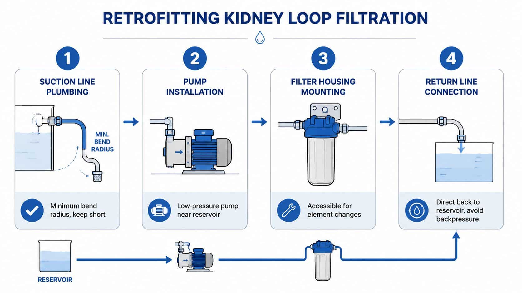
Start at the reservoir. Keep the suction line short, use generous internal diameter and respect the hose's minimum bend radius. Place the strainer where it can be inspected and cleaned without draining the tank, and support the pump and motor on anti-vibration mounts rather than allowing pipework to carry their weight.
Build the circuit in a controlled sequence
-
Isolate the reservoir connection. Confirm the oil level, tank access and safe isolation points before opening the circuit.
-
Install the suction side first. Avoid sharp elbows and unnecessary reducers. An undersized inlet line can starve the pump even when the filter outlet appears unrestricted.
-
Mount the pump securely. Keep it close to the reservoir, but leave enough access for inspection, seal replacement and electrical isolation.
-
Fit the housing where the element can be changed. Differential pressure indication should be visible during routine rounds, not hidden behind guards or inside a crowded enclosure.
-
Route the return correctly. Discharge the cleaned oil back into the reservoir away from the suction pickup. Opposing the two connections helps prevent immediate short-circuiting of the conditioned flow.
Respect pressure and electrical limits
An offline circuit isn't a substitute for the main pressure line. Many compact arrangements are designed around a maximum of 4 to 6 bar, so confirm the actual housing, element and pump ratings before commissioning. Exceeding the filter circuit's pressure limit can collapse the element, damage seals or create a hazardous housing failure.
Dedicated motors need suitable overload protection, isolation and control logic. Decide whether the loop should run continuously, during machine standby, or only under a maintenance schedule. Interlocks can prevent operation when an isolation valve is closed or the reservoir level is too low.
Mobile plant often needs a compact skid with protected hoses and guarded controls. Industrial installations may have a permanent frame or filtration room, but the same principles apply. UK electrical work must be completed by a competent person, and the complete installation should be reviewed for applicable pressure-equipment, guarding and workplace-safety obligations.
Installation warning: A pump that sounds like it is drawing gravel usually has an inlet problem. Check the strainer, oil level, suction hose and air ingress before changing the filter element.
Air locks are another common fault. Prime the pump, open the return path and verify that the circuit can vent safely before expecting stable flow. If the loop works only with a bypass valve partly open, don't accept that as normal operation. Find the restriction and correct the design.
Maintenance Routines and Troubleshooting Common Issues
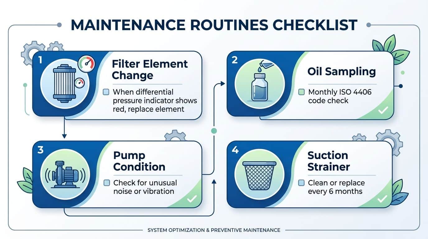
Kidney loop filtration should sit inside the existing MRO routine, not operate as an unattended bolt-on. The most useful records combine differential pressure, oil samples, pump condition and element changes so the team can see whether contamination is reducing or being moved around the circuit.
Change elements from condition, not from an arbitrary calendar date. A rising differential pressure indicates loading, but the correct replacement point must follow the element and housing manufacturer's limit. One system may load quickly after a repair, while another may run for much longer once the reservoir and machine are clean.
Use the evidence from the circuit
Take samples from a consistent point, ideally downstream of the kidney loop filter or from a defined live sampling port. Compare like with like. A sample taken from the bottom of a dirty tank may answer a different question from one taken in the circulating clean-oil line.
- High particle counts: Check element bypass settings, housing seals, incorrect element fitment and sample contamination.
- Pump noise or vibration: Inspect the suction strainer, inlet hose, oil level and air leaks before condemning the pump.
- Moisture breakthrough: Check tank breathers, cooler integrity, outdoor exposure and whether the fitted stage removes the type of water present.
- Rapid differential-pressure rise: Look for a contamination event, internal component failure, degraded oil or a filter that is too small for the duty.
Use particle counting services and guidance to establish a repeatable monitoring approach. Trend the results against maintenance events, filter changes and component work. A single clean result doesn't prove that the entire system is healthy, while a deteriorating trend may justify investigation before a valve begins sticking.
Know when the loop is outmatched
A kidney loop maintains and improves fluid condition, but it won't repair a damaged pump, remove heavy sludge instantly or correct an active source of contamination. Persistent debris after a component failure may require flushing, tank cleaning or oil replacement before normal polishing can resume.
Dispose of used elements and contaminated oil through the site's approved waste route. Keep records of the waste stream, especially where oil contains water, metal fines or other regulated contaminants. Good environmental control also helps the financial case because it exposes cost of treating oil as a disposable consumable.
Industry Applications Across Mobile and Industrial Hydraulics
The strongest applications share a common feature, a small contamination problem can create a disproportionately large operational problem.
On excavators and telehandlers, dust enters through damaged rod seals, poor breather arrangements, dirty service connections and open tanks. An offline loop can condition the reservoir while the machine is parked, but the retrofit must survive vibration, weather, hose movement and limited space. Protecting proportional or servo-controlled functions may justify the equipment where a valve replacement would disrupt a busy hire or construction operation.
Agricultural machinery presents a different operating pattern. Combines and forage harvesters may work intensely during a short season and then stand idle. A portable kidney-loop cart can polish oil during the off-season without running the engine or loading the main hydraulic circuit. That makes the arrangement useful where the maintenance team controls the storage period and can connect the equipment safely.
Gearboxes need a different conversation
A gearbox circuit isn't a hydraulic reservoir with different labels. Oil viscosity, bearing lubrication, splash levels, seals, cooler performance and water ingress all affect the specification. Fine particle filtration can help protect bearings and gears, but the suction arrangement must avoid removing oil from a point that compromises lubrication during operation.
Wind-turbine gearboxes, marine winches and steel-mill rolling stands can justify permanent offline conditioning because access is difficult and failure consequences are serious. Yet the loop still needs oil analysis, correct water management and a clear response plan for metal wear debris. A filter that removes particles without identifying why they appeared can delay diagnosis of an active bearing or gear problem.
Retrofit reality matters
Most aftermarket projects begin with a symptom, not a clean design brief. The engineer has a rising particle count, sticky valve, shortened element life or unexplained oil degradation. Before installing a loop, establish the contamination source and take a baseline sample.
A portable unit may be the better first move where the same maintenance team services several machines. A permanent system makes more sense where one asset has continuous exposure, difficult access or a failure cost that outweighs the installation. The hardware should fit the maintenance strategy, not become another asset that nobody checks.
Making the Business Case and Next Steps
The decision threshold is economic, but it isn't determined by reservoir size alone. A reservoir below 200 litres can still justify kidney loop filtration when it feeds high-value servo components, suffers repeated contamination or causes expensive downtime. Conversely, a larger tank may not warrant a permanent loop if the oil remains clean, the machine is non-critical and existing filtration already meets the component requirement.
Start with four facts:
- Current condition: Record the latest ISO 4406 code and sample location.
- Failure history: Identify pump, valve, gearbox and actuator failures linked to contamination.
- Fluid cost: Include oil, labour, disposal and the time required to change it.
- Operational exposure: Quantify the consequence of taking the machine out of service.
Then compare the installed cost of the pump, housing, elements, pipework and electrical work with the avoidable cost of failures and fluid changes. Don't count an oil-drain extension unless sampling confirms that the oil remains fit for service. Don't count a component saving unless the contamination mechanism is plausible and the loop is specified to address it.
For some small, low-risk circuits, improved in-line filtration, better breathers and stronger housekeeping are the right answer. For critical mobile plant, industrial power units and gearboxes, independent conditioning can be a practical retrofit that improves control over cleanliness without redesigning the main hydraulic circuit.
MA Hydraulics Ltd can help assess kidney loop filtration requirements, select compatible pumps, filters and hydraulic components, and develop bespoke power solutions for mobile or industrial equipment. Phone 01724 279508 today or visit MA Hydraulics Ltd to discuss your reservoir, gearbox circuit, contamination results and the most defensible route to a reliable return on investment.
