
You're often at the same decision point when a machine spec lands on the desk. The application needs smooth speed control, fast reversal, decent starting torque, and it can't waste power as heat. That might be a harvester drive, a recovery winch, a mixer drum, or an industrial handling circuit that has to behave predictably every shift.
In those jobs, the choice of hydraulic architecture decides far more than layout. It affects cooling load, reservoir size, filtration strategy, control feel, serviceability, and how forgiving the machine will be when it starts ageing in the field.
A closed loop system suits that kind of work because it's built around control and efficiency, not just fluid transfer. But it only delivers those benefits when the pump, motor, charge circuit, valves, and maintenance plan are chosen as one package rather than as a shopping list of parts.
Introduction to Hydraulic System Design
A typical example is a vehicle-mounted winch drive. The operator wants feathered control at low speed, solid pull when the line tightens, and immediate reversal without a clumsy transition through neutral. An open circuit can do the job, but you usually end up managing compromises with valve losses, extra heat, and a larger tank than the application really wants.
That's where engineers start looking seriously at a hydrostatic drive. A closed loop arrangement gives you a more direct relationship between the prime mover and the hydraulic motor. For mobile equipment, that usually means better controllability when load changes quickly. For industrial machinery, it often means a tidier package and more consistent response.
If you need a refresher on the basics before getting into circuit architecture, it helps to revisit how hydraulics work in practical terms. The fundamentals still matter because most closed loop problems aren't mysterious. They come back to pressure, flow, leakage, heat, and contamination.
The first questions worth asking
Before selecting components, it's worth being blunt about the duty:
- What does the load do? Constant speed conveyor duty is a different problem from a traction drive that accelerates, decelerates, and reverses.
- How fine does control need to be? If the operator needs repeatable positioning or smooth creep, the control package matters as much as the pump.
- Where will the machine live? Agricultural kit, mobile plant, and factory systems all punish hydraulics differently.
- What happens when maintenance slips? Some circuits tolerate poor service habits better than others.
Practical rule: If the application needs frequent reversal, variable speed, compact packaging, and strong operator feel, a closed loop system deserves serious consideration early, not as an upgrade after an open circuit struggles.
Closed loop design isn't automatically the right answer. It's the right answer when performance justifies the extra thought.
What Is a Hydraulic Closed Loop System
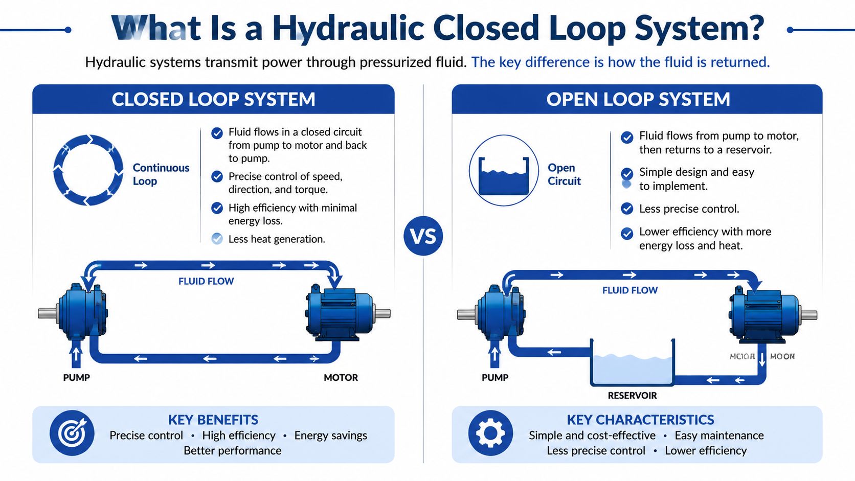
A hydraulic closed loop system is a circuit where the pump and motor exchange most of the working flow directly with each other. In a closed-loop hydraulic system, also known as a hydrostatic drive, the pump draws most of its flow directly from the return flow of the actuator rather than from a reservoir, so the fluid circulates between pump and motor without returning to a tank after each cycle, as outlined in this comparison of closed-loop and open-loop hydraulic systems.
That single difference changes the whole character of the machine. In an open circuit, the pump draws from the tank and returns to the tank. In a closed loop system, the main flow remains in the pressurised loop and only a smaller support flow handles replenishment, cooling, and housekeeping duties.
Closed loop versus open loop in practice
The simplest way to describe it is this. An open circuit behaves more like draw, use, return. A closed circuit behaves more like circulate, correct, and replenish.
A heating circuit is the better mental model for closed loop work. The fluid keeps circulating around the same path. A garden tap is closer to open loop thinking, where the source and return are separated by a reservoir path.
| Characteristic | Open Loop System | Closed Loop System |
|---|---|---|
| Main fluid path | Pump draws from reservoir and returns to reservoir | Pump and motor recirculate most of the main flow directly |
| Reservoir role | Primary fluid source and return destination | Support function for replenishment, cooling, deaeration, and losses |
| Speed reversal | Usually needs directional valve strategy | Commonly handled by pump displacement reversal |
| Control feel | Functional but often less direct | More precise and responsive in demanding drives |
| Package size | Typically needs a larger tank | Usually allows a smaller tank arrangement |
| Typical use | Simpler circuits and general hydraulics | Hydrostatic drives and performance-focused machinery |
Why the reservoir still matters
Closed loop doesn't mean tankless. It means the tank has a different role. A closed-loop system still requires an oil reservoir, but it is significantly smaller than the reservoir used in open-loop systems because the fluid is recycled within the pressurised circuit between the pump and motors or actuators, as explained in this overview of closed circuit displacement control.
That smaller reservoir is useful on mobile machinery where space is always under pressure. But it also means you can't treat the tank as a lazy fix for bad thermal management or poor contamination control. The system has less forgiveness.
The biggest mistake is thinking a closed loop system is just an open circuit with fewer hoses. It isn't. It's a different design philosophy.
Key Components and Their Functions
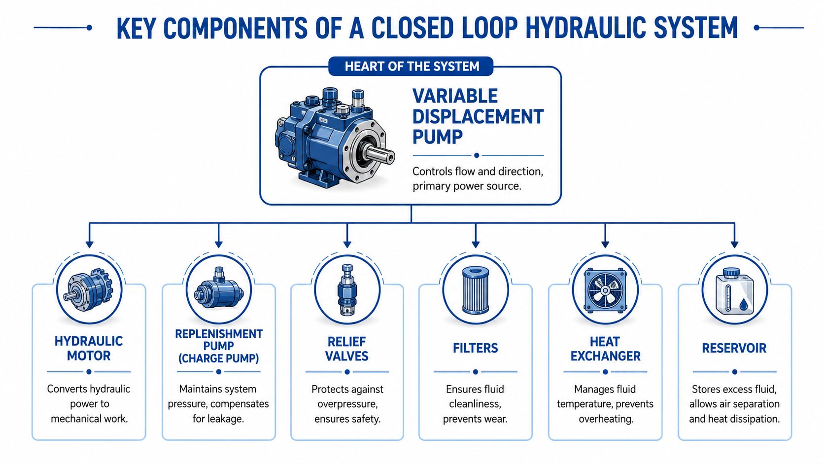
The centre of most closed loop systems is the variable displacement pump. That pump controls how much flow moves around the loop and, in many drive arrangements, it also controls direction by changing swash plate position through centre. That's why pump choice has such a big effect on machine feel.
Pump and motor matching matters more than many drawings suggest. A good schematic can still become a poor machine if the pump's control characteristics don't suit the motor's displacement, inertia, and the actual load profile. That's especially true where operators demand smooth creep speed and stable transition into higher travel speed.
For component context, it's useful to look at hydraulic pumps and motors used across mobile and industrial systems. The key is never to size them in isolation. The loop has to work as a system.
The pump and motor pair
The pump creates the loop flow. The motor converts that hydraulic energy back into mechanical output. In practical design work, this pair decides:
- Low-speed behaviour
- Starting torque feel
- Reversing smoothness
- Top speed capability
- Heat generated under partial load
A reversible drive that spends its life shuttling in short cycles wants different tuning from a drum rotation circuit that runs steadily for long periods. Engineers get into trouble when they size only for peak duty and ignore transitional behaviour.
A useful visual reference sits below.
The charge pump and support circuit
A closed loop can't survive on main loop flow alone. It needs a charge pump to maintain positive pressure on the low-pressure side, make up internal leakage, support flushing, and feed cooling and filtration functions. To ensure adequate fluid availability for flushing, cooling, and maintaining charge under all operating scenarios, the charge pump displacement must be at least 10 percent of the maximum flow rate moving around the loop, according to this hydrostatic drive design explanation.
That's a practical design rule, not a substitute for engineering judgement. If the machine has harsh duty, high ambient temperature, or repeated directional changes, the support circuit deserves extra scrutiny.
Protection and conditioning parts
The parts that seem secondary on the schematic often decide whether the machine lasts.
- Relief valves protect the loop from overload and transient shock.
- Flushing valves pull hot, contaminated oil from the low-pressure side so cooler, cleaner oil can enter from the charge circuit.
- Hot oil shuttle valves help direct the hottest side of the loop to the cooler path.
- Filters protect precision parts from contamination.
- Heat exchangers manage the thermal load that closed circuits typically concentrate.
A closed loop system usually fails from the support circuit first. Not because the pump is weak, but because charge pressure, cooling, or cleanliness was treated as secondary.
What works and what doesn't
What works is a balanced circuit where control, replenishment, relief protection, and cooling were designed together.
What doesn't work is fitting a good variable pump to a poorly considered support package, then expecting the machine to tune itself out in service.
Weighing the Benefits and Drawbacks
Closed loop hydrostatic drives earn their place when efficiency and controllability matter enough to justify a more specialised circuit. In UK-regulated mobile and industrial hydraulic applications, closed-loop hydrostatic drive systems using variable displacement pumps demonstrate 15–20% higher energy efficiency than open-loop systems by matching pump output to actual demand, according to this guide on open versus closed loop hydraulic systems.
That gain is meaningful on machinery that spends long hours under variable load. Less wasted flow usually means less heat to remove and better use of engine or motor input power.
Why engineers choose them
The strongest reasons are usually operational, not theoretical.
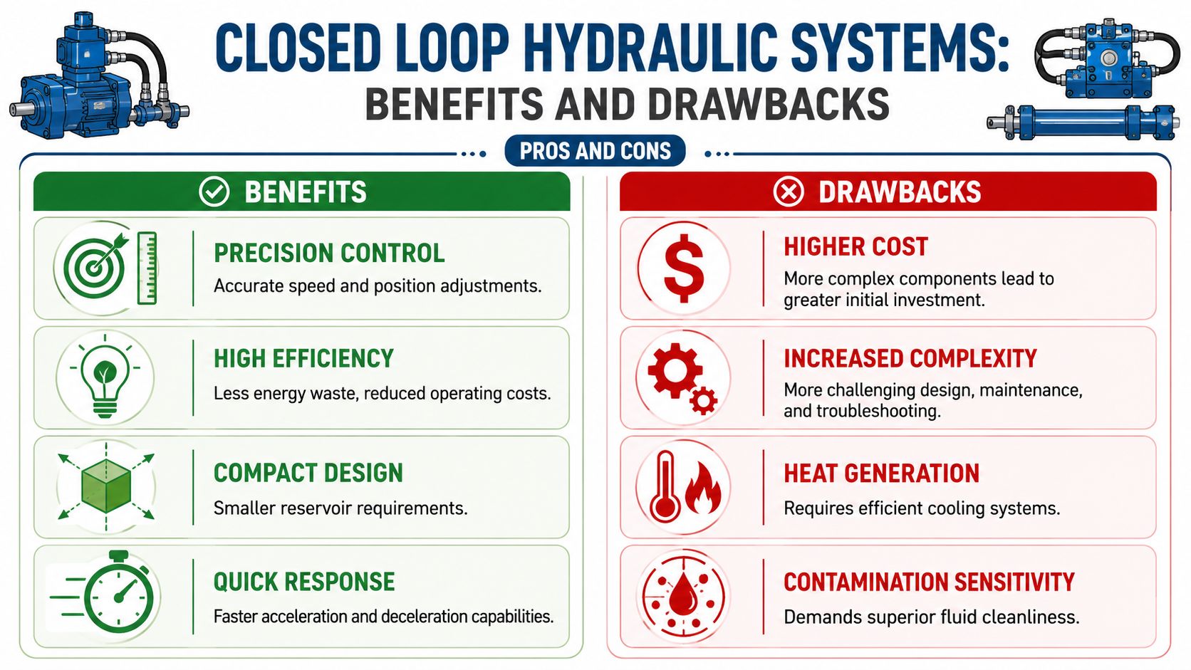
- Control quality improves because the drive responds directly to pump displacement changes.
- Compact packaging becomes easier because the reservoir can be smaller than a comparable open circuit arrangement.
- Dynamic performance is better suited to acceleration, deceleration, reversal, and controlled braking.
- Energy use is more disciplined because the pump doesn't have to deliver surplus flow just to be throttled away downstream.
For mobile machinery, this often translates into better drivability. For industrial plant, it can mean smoother production movement and fewer operator corrections.
Where the drawbacks bite
The trade-offs are real.
A closed loop system is usually more expensive to specify correctly because it depends on more specialised components. The circuit is also less tolerant of poor oil condition, poor charge pressure control, and weak cooling design. When contamination gets into a closed loop, precision components feel it quickly.
The maintenance team also loses some forgiveness. A neglected open circuit may limp on while wasting power. A neglected closed circuit often shows up as poor response, overheating, instability, or noisy operation much sooner.
If the application doesn't need the performance, the extra sophistication can become a burden rather than a benefit.
A sensible selection test
Choose closed loop when the machine needs performance and will receive disciplined maintenance.
Stay open loop when simplicity, lower initial cost, and easier general service matter more than precise hydrostatic drive behaviour.
Common Applications in UK Machinery
Closed loop systems turn up where operators expect the machine to feel deliberate rather than approximate. In UK mobile equipment, that includes propulsion and drive duties where speed must vary continuously and reversal has to be immediate without a clumsy valve sequence.
A combine harvester is a good example. Travel speed changes constantly with crop conditions, terrain, and unloading movements. The drive needs controllable torque at low speed, but it also needs smooth modulation so the operator isn't fighting the machine all day. A closed loop system suits that job because the pump and motor can be tuned around variable traction demand rather than around a simple on-off flow path.
Mobile machinery examples
Telehandlers and similar plant also benefit when hydrostatic traction is expected to feel predictable during short shuttle movements. Repeated direction changes, yard manoeuvres, and inching behaviour all favour a circuit that can modulate speed and direction cleanly.
Concrete mixer drum drives are another practical fit. The duty isn't the same as a traction circuit, but the requirement for controlled rotation and reversal still points toward hydrostatic thinking in many machine layouts.
- Agricultural propulsion where ground speed and load keep changing
- Materials handling drives where smooth directional changes matter
- Vehicle-mounted auxiliaries such as winches or specialist rotating equipment
Industrial uses that justify the extra complexity
In factories and processing plants, closed loop systems make sense where the load is heavy, directional changes are frequent, or positioning must be more controlled than a basic open circuit will comfortably provide.
Winch and hoist drives are a common fit because operators want repeatable control as the load changes. Conveyor and handling systems can also justify closed loop architecture where smooth acceleration protects product or reduces shock through the machine frame.
On industrial machinery, the closed loop system usually proves its value when poor control costs more than the extra hydraulic complexity.
Why some applications still stay open loop
Not every machine benefits enough to justify the circuit. If the job is simple, runs one direction at broadly fixed speed, and has generous installation space, an open circuit often remains the more sensible answer.
That's why application discipline matters more than trend-following. Closed loop isn't the premium option by default. It's the right option for a narrow group of demanding duties.
Design Maintenance and Troubleshooting
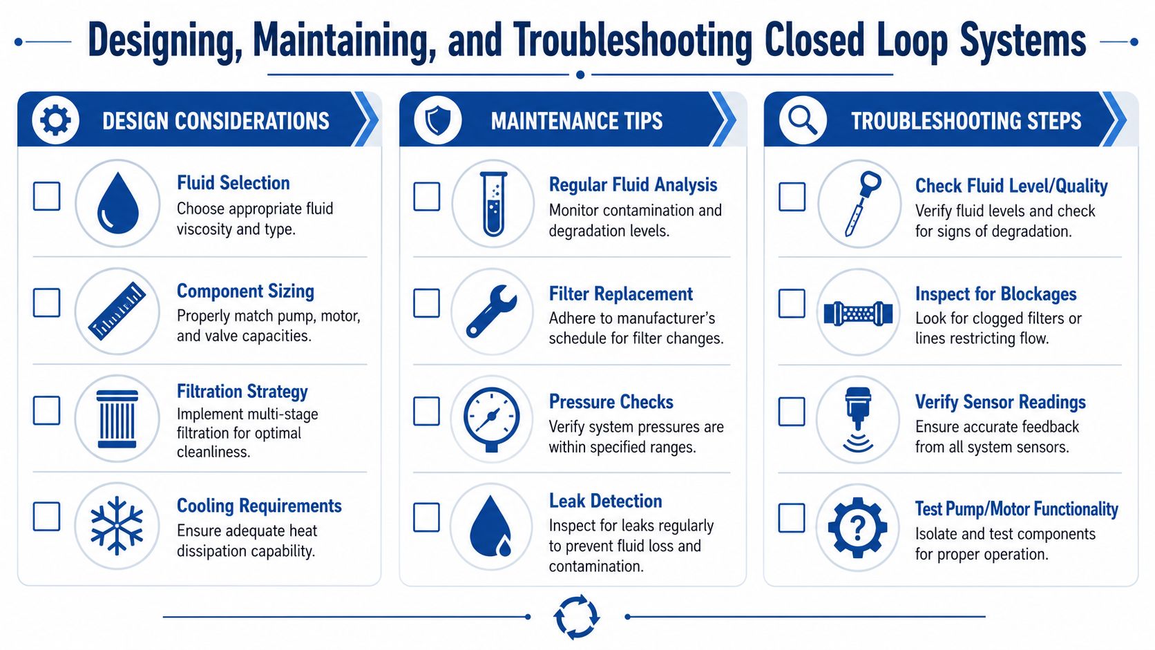
Good closed loop performance starts on the drawing board. Most service headaches can be traced back to one of three early mistakes: poor component matching, weak contamination control, or inadequate thermal planning.
Designers also need to remember that hydraulic closed loop systems don't sit in the same regulatory discussion as open-loop water systems. A common unresolved question in UK practice is how Environment Agency licensing and BSRIA guidance relate to hydraulic closed circuits versus water-based systems. The distinction is often poorly explained, particularly for mobile versus industrial machinery, as highlighted in this discussion of the gap around UK closed-loop guidance.
Design choices that deserve attention
Start with the obvious pair. Pump displacement and motor displacement must suit the true duty, not the sales description of the machine. If the circuit has to creep, reverse under load, and hold steady under changing torque, the control method deserves the same attention as the displacement figures.
Valve selection also matters more than many teams expect. For closed-loop control operation, UK-based electronics manuals specify precise valve spool overlap compensation through signal step adjustments to eliminate deadband effects in proportional and directional valves, which can otherwise reduce responsiveness by up to 30% in high-frequency cycling applications, according to Parker's manual for closed-loop control operation.
That matters on bespoke power packs, materials handling systems, and mobile machinery where the complaint isn't “it doesn't work” but “it feels lazy”, “it hunts”, or “it doesn't pick up cleanly from neutral”.
Maintenance habits that actually protect the loop
Closed loop systems reward disciplined service. They punish casual service.
- Keep the oil clean. Precision pumps, motors, and proportional elements don't tolerate contamination for long.
- Watch charge pressure behaviour. A machine can still move while charge conditions are already slipping into a damaging range.
- Treat heat as data. Rising operating temperature usually means something changed. It isn't normal background noise.
- Inspect flushing and cooling paths. These support functions are easy to ignore because the machine may still appear to run.
For teams looking outside hydraulics for broader thinking on durability, these engineering insights on pump reliability are useful because the underlying lesson is the same. Cavitation, wear, and fluid condition don't stay local. They spread through the system.
A practical fault-finding sequence
When a closed loop drive turns sluggish or unstable, resist the temptation to blame the main pump first.
- Check fluid condition and level. Darkened oil, aeration signs, or contamination often indicate the underlying issue.
- Confirm charge circuit health. Weak replenishment causes symptoms that resemble a failing pump.
- Review filter condition and pressure indicators. Restriction can destabilise the support side of the loop.
- Measure temperature trend. Heat tells you whether losses have increased or cooling has fallen away.
- Assess control signal and valve response. Deadband and poor calibration often look like hydraulic weakness.
If your team needs a structured approach, this hydraulic troubleshooting methodology is a useful starting point for separating root cause from secondary symptoms.
Don't start with the expensive component. Start with the condition of the fluid, the charge side, and the control signal. That's where many closed loop faults reveal themselves.
Safety and control integrity
Where test benches or high-risk automated systems are involved, control architecture matters as much as the hydraulic circuit. Closed-loop hydraulic test bench control systems may require redundant channels with diverse technology to achieve performance level PLd, including common cause failure analysis under EN 13849-1 Annex F, as described in this article on closed-loop hydraulic test bench safety architecture.
That level of safety planning won't apply to every machine, but it does underline the point. A closed loop system isn't just a fluid circuit. It's a controlled system, and the controls deserve engineering rigour.
Your Partner in Hydraulic System Design
Choosing between open and closed loop architecture comes down to the duty, the control requirement, the available installation space, and how disciplined maintenance will be over the machine's life. For demanding mobile and industrial machinery, a closed loop system often gives the better answer because it combines compact packaging with strong controllability and efficient power transfer.
But the margin between a refined hydrostatic drive and a troublesome one is rarely accidental. It comes from correct pump and motor matching, sensible charge circuit design, proper filtration, realistic cooling provision, and control tuning that reflects the actual duty cycle.
The same principle applies outside hydraulics too. When a project depends on specialist integration rather than commodity supply, partner selection matters. That's true whether you're specifying a drive package or choosing a software development partner for a control or monitoring layer around the machine.
If you're designing new equipment, replacing ageing assemblies, or trying to get a difficult hydrostatic system behaving properly, technical support at component-selection stage saves time later.
For application advice, replacement components, and bespoke hydraulic solutions, contact MA Hydraulics Ltd. Phone 01724 279508 today, or send us a message.
