
A lot of readers land on this topic when the machine is already hot, the oil temperature is climbing, and production is starting to wobble. On mobile plant, you see it first as sluggish response, fan noise, or repeated high-temperature alarms. In a factory, it often shows up as drift in cycle quality, nuisance shutdowns, and seals or hoses ageing faster than they should.
That's why cooling system design needs to be treated as part of the hydraulic circuit, not as an accessory added at the end. If the cooler, pipework, controls and installation details don't match the actual heat load, the system will always be fighting itself.
The Unseen Threat of Overheating in Hydraulic Systems
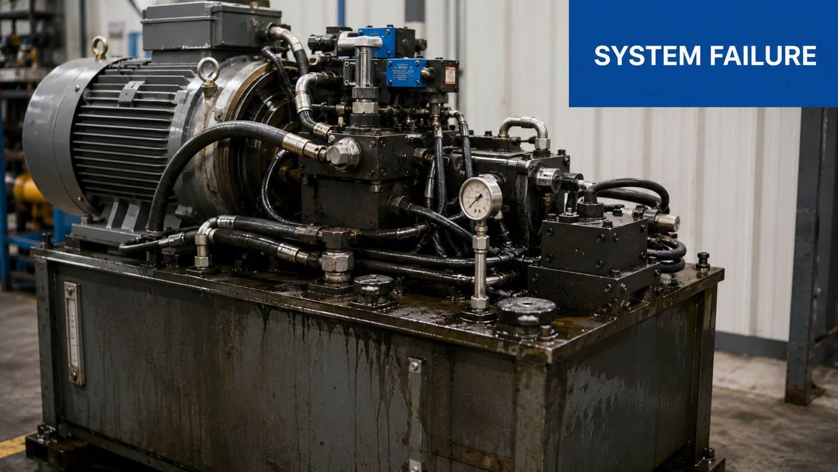
A hydraulic system rarely fails from temperature in one dramatic moment. More often, it spends weeks running a little too warm, a little too often, until wear becomes obvious. A machine that worked acceptably in spring starts struggling in midsummer. The operator compensates. Maintenance cleans the core, changes the oil, and the problem returns.
That pattern is common because overheating is often designed in. The pump inefficiency, valve losses, line restriction, poor airflow and high ambient conditions were all present from day one. They just weren't severe enough to expose the weakness until the duty cycle changed.
In the wider UK picture, cooling isn't a niche issue. In 2019, the United Kingdom consumed approximately 6,187 GWh of energy for cooling, and cooling demand accounted for nearly 10% of total UK electricity demand, which shows how important efficient cooling system design is for reducing waste and improving performance in industrial applications, according to the UK cooling energy overview.
What overheating actually costs in practice
When oil runs too hot, several problems stack up at once:
- Viscosity drops: the fluid thins out, internal leakage rises, and the system creates even more heat.
- Seal life shortens: shaft seals, O-rings and hose compounds harden or lose elasticity.
- Control quality slips: proportional valves and fine metering functions become less consistent.
- Contamination risk increases: oxidised oil and degraded additives make filtration work harder.
Practical rule: If the machine only behaves properly when ambient conditions are mild, the cooling system probably isn't sized around the real duty.
A proper design starts with the whole thermal picture. Tank size matters. Airflow matters. Return line routing matters. So does the actual duty cycle, not the optimistic one written on a commissioning sheet. Anyone dealing with hydraulic packs regularly will recognise that thermal management is inseparable from reliability. For a broader look at that relationship, this guide to hydraulic thermal management is worth reading.
Why reactive fixes usually disappoint
The common late-stage fixes are familiar. Fit a bigger fan. Add a cooler in the return line. Open up access panels. Sometimes that helps, but only if the underlying heat balance is understood first.
If the system is generating more heat than the cooler can reject, adding hardware without calculation just shifts the symptoms. Good cooling system design prevents that by treating heat as a measurable load from the start.
Where Does the Heat Come From
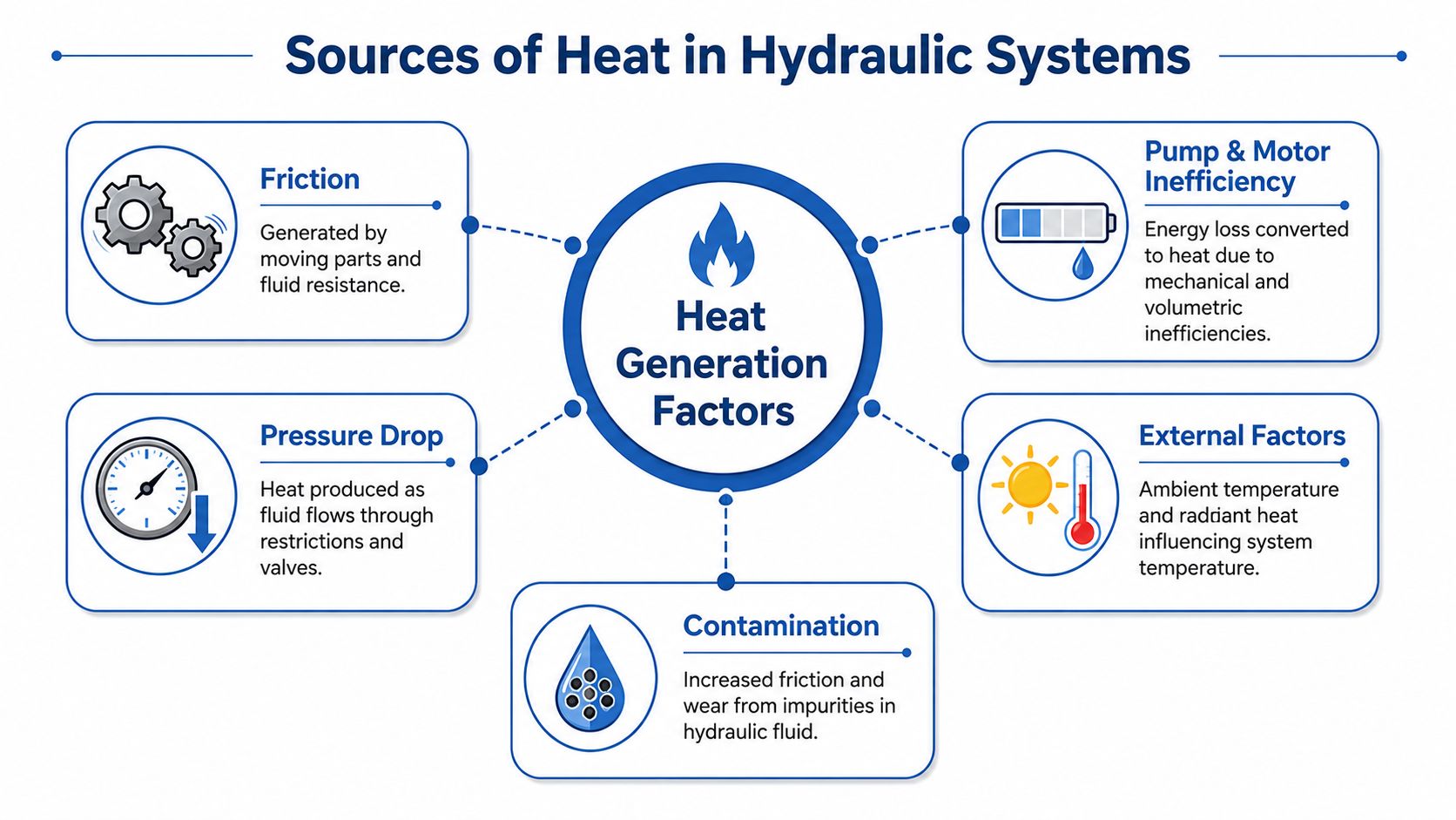
Heat in a hydraulic circuit is wasted energy. The useful part of the input power moves a cylinder, turns a motor, or holds a load. Everything else ends up as heat in the oil, the metalwork, or the surrounding air.
Once you look at a circuit that way, overheating becomes easier to diagnose. You stop asking only whether the cooler is large enough and start asking where the losses are being created.
Internal losses inside the hydraulic circuit
The first source is the pump. No pump is perfectly efficient. Mechanical losses in bearings and gears, plus volumetric losses from internal leakage, all turn input power into heat. The same applies to hydraulic motors.
Valves are another major contributor. Every pressure drop across a relief valve, proportional valve, flow control, or restrictive manifold passage produces heat. If a relief valve is cracking too often, or a directional valve is forcing flow through a tight path, the system is effectively using pressure to warm the oil.
Pipework and hoses add their share as well. Long runs, undersized bores, sharp bends and unnecessary fittings create frictional losses. Those losses don't disappear. They raise the fluid temperature.
External conditions make a bad system worse
Ambient conditions don't create the original inefficiency, but they reduce your margin for error. A machine that survives in cool weather can struggle badly during hotter spells. That matters more now because UK summer temperatures rose 2.1°C in the last decade, with 18% more days exceeding 30°C in regions like Lincolnshire, increasing thermal stress on mobile and fixed hydraulic machinery, as noted in this UK heat and cooling discussion.
A cooler can only reject heat if there's a useful temperature difference between the oil and the surrounding medium.
That's why mobile plant in enclosed engine bays often suffers first. Dust loads the core, airflow is compromised, and radiant heat from the engine and exhaust raises the air temperature around the cooler.
A practical heat map of the usual culprits
When tracing heat generation, check these areas in order:
- Pump operating point: is it working near a condition where internal leakage rises?
- Relief activity: is the system spending time across relief instead of doing useful work?
- Valve restriction: are pressure drops across control valves higher than expected?
- Line sizing: are hoses or tube runs too small for the flow rate?
- Fluid condition: contamination increases friction and accelerates wear.
For engineers working around machining systems as well as hydraulics, fluid behaviour under heat and contamination is also discussed well in this essential guide for metalworkers. Different fluid types, same lesson. Heat control and cleanliness are closely linked.
Performing Essential Thermal Calculations for Sizing
A cooling job usually goes wrong long before the pack is built. I see the same pattern on UK power packs and mobile machines. Someone picks a cooler from a catalogue, checks that it fits the frame, and treats the thermal side as a secondary detail. The machine then comes back with hot oil on summer duty, slow cycle times, and shortened seal life.
Good sizing starts with the heat the system must reject in service, not the cooler size you hope will be enough.
Start with the real heat load
For hydraulic systems, two calculation routes are useful.
The first is the loss method. Input power goes into useful work, pressure losses, leakage, and mechanical inefficiency. The part that does not become useful output becomes heat in the oil. This method is often the quickest route on a power pack where motor size, pressure, flow, and duty cycle are already known.
The second is the heat rejection method:
Heat transfer relationship: P = m × c × ΔT
Where:
- P is heat load in kW
- m is mass flow rate of the cooling medium
- c is specific heat capacity
- ΔT is the temperature rise across the cooler
Use this method when coolant flow, air flow, or water flow is known and you need to confirm whether the proposed cooler can carry the load away.
Both routes are valid. The better one depends on what data you trust.
Keep the numbers honest
Thermal sheets fail when the assumptions are too tidy. Real machines do not run at catalogue duty. Relief events last longer than planned, enclosure temperatures rise, fan guards clog, and return oil temperature can sit above the original estimate for hours.
A sensible sizing exercise for UK industrial and mobile equipment should include:
-
Continuous and peak duty
Record the load profile, not just rated pressure and maximum pump flow. -
Expected ambient condition
Use the actual installation environment, especially for engine bays, acoustic enclosures, and indoor plant rooms. -
Target operating oil temperature
Set a band that supports viscosity, seal life, and component efficiency. -
Allowance for fouling and ageing
Core cleanliness, fan wear, and water-side scale all reduce performance over time. -
Pressure drop across the cooler circuit
Heat rejection is only half the job. Excess restriction wastes power and creates more heat.
For many projects, I calculate the load from hydraulic losses first, then check the proposed cooler against realistic oil flow and available temperature difference. That catches bad assumptions early.
Use metric units throughout
Keep the whole calculation in SI units. It reduces mistakes and matches normal UK engineering practice.
A practical worksheet uses:
- kW for heat load or power loss
- L/min for oil flow, converted where needed
- kg/s for mass flow in heat transfer calculations
- °C for temperature rise
- kPa or bar for pressure, with bar used where it improves readability on hydraulic schematics
The metric standard guidance sets out the SI basis clearly. In hydraulic work, the main point is straightforward. Stay consistent and avoid obsolete pressure units.
A practical sizing workflow
Use the same order every time. It saves rework.
1. Define the duty cycle properly
Separate continuous load from intermittent peak load. A machine that spends five minutes in every twenty on high-pressure clamp or winch duty should not be sized on the average alone.
2. Estimate the heat generated in the hydraulic circuit
For a first pass, calculate losses from pump inefficiency, valve pressure drops, line losses, and any deliberate throttling. If relief operation is part of the cycle, include it explicitly.
3. Set the allowable oil temperature range
Design for the temperature the machine should run at, not the highest temperature the oil can survive. Those are different limits.
4. Check available cooling medium conditions
For air coolers, that means realistic ambient air temperature and actual airflow through the core. For water coolers, it means supply temperature, quality, and stable flow.
5. Add margin for service conditions
Allow for dirt on the core, reduced fan performance, and seasonal variation. Margin should reflect the application, not guesswork.
6. Verify cooler circuit pressure loss
If the cooler and pipework add too much resistance, the system pays for it continuously.
If you are comparing packaged hydraulic oil coolers for industrial and mobile applications, apply this workflow before looking at catalogue capacity tables. Rated output only matters when the test conditions resemble your installation.
This video gives a useful visual refresher on the basic thinking behind cooling calculations and cooler choice:
Check the whole thermal path
A cooler that looks adequate on paper can still miss the duty. The usual reason is not the core itself. It is the installation around it.
An oil-to-air unit mounted in a tight engine bay may be drawing pre-heated air. A water-cooled unit may have enough exchanger area but poor water quality and falling flow. Engineers familiar with wider building and plant services see the same principle in HVAC systems. Heat rejection depends on the full circuit, not one selected component.
This is also where many hydraulic designs drift off course. The calculation sheet assumes stable flow through the cooler, but the installed machine has a bypass valve set too low, a long return line, or a core mounted where recirculated hot air feeds straight back into the fan.
What usually gets missed
Three checks catch a lot of field problems:
-
Peak load coincidence
Size for the credible worst operating case, especially where high pressure and low vehicle speed happen together on mobile plant. -
Cooler bypass behaviour
A poor bypass arrangement can protect cold oil start-up but starve the cooler once the system is hot. -
Layout review at calculation stage
Fan clearance, ducting, exhaust position, service access, and hose routing should be checked while the thermal load is still being calculated.
A thermal calculation is only useful if it survives contact with the installed machine. That is why I prefer a workflow that starts with losses, checks cooler capacity against real site conditions, and then tests the answer against packaging and controls before anything is ordered.
Selecting the Right Cooler and System Components
Once the heat load is known, component selection becomes a trade-off exercise. There isn't a universally best cooler. There's a cooler that suits the duty, the environment, the available services and the space you have.
For most hydraulic packs, the primary decision is between oil-to-air and oil-to-water cooling. Both can work well. Both can fail badly when applied in the wrong setting.
Oil-to-air or oil-to-water
Oil-to-air coolers are often the practical choice on mobile machinery and standalone industrial packs. They're self-contained, easier to retrofit, and don't depend on site water quality or a secondary cooling circuit.
Oil-to-water coolers fit better where a stable water supply already exists, or where ambient air temperature makes air cooling less attractive. They can be compact for the duty, but they introduce another service circuit, another maintenance point and another contamination risk if the exchanger fails internally.
| Cooler Type | Typical Efficiency | Installation Cost | Best For… | Key Consideration |
|---|---|---|---|---|
| Oil-to-air | Application-dependent and highly sensitive to airflow, ambient temperature and core cleanliness | Usually simpler on standalone systems | Mobile plant, outdoor equipment, compact industrial packs without site water | Fan performance and airflow path matter as much as core size |
| Oil-to-water | Application-dependent and often more stable where water conditions are controlled | Often higher because pipework and water integration add complexity | Fixed plant with an established cooling water circuit | Water quality, fouling and leak management need close attention |
Pipe and hose sizing is part of cooler selection
A common mistake is spending time on the exchanger and almost none on the line sizing around it. That can undo the whole job. UK engineering standards set fluid velocity thresholds at 3 to 4 m/s for pressure lines up to 35 bar and up to 7 m/s for lines over 200 bar, with higher velocities capable of causing destructive forces, as outlined in these hydraulic design guidelines.
That means the cooler circuit should be checked as a flow system, not just a heat exchanger package.
- Pressure side lines: keep velocity within the suitable range for the working pressure.
- Suction lines: avoid high velocity that encourages cavitation risk and unstable pump conditions.
- Return paths through the cooler: don't assume a compact connection size is acceptable just because it matches the cooler ports.
Fittings and standards matter in UK builds
Metric discipline matters here. UK hydraulic systems should use metric fittings aligned with DIN and ISO standards. Incorrect sizing, or mixing thread types across systems, is a reliable route to leakage and mechanical trouble.
Metric hydraulic fittings also have a 24° cone angle and need to comply with ISO 6149-1, DIN 3852-1 and BS EN ISO 12151-2 for dimensional accuracy and safe high-pressure service, as described in this hydraulic fitting guide. In practical terms, don't treat fittings as generic hardware. Treat them as pressure components.
Decision points that usually settle the choice
If the application is mobile, dirty and exposed to changing weather, oil-to-air is often easier to package and maintain. If the application is fixed, enclosed and already connected to building services, oil-to-water may make more sense.
If you're comparing broader thermal equipment layouts beyond hydraulics, reviewing how different HVAC systems are packaged can also be helpful. The details differ, but the same design logic applies. Heat rejection performance depends on airflow, service access and system balance, not just nominal unit size.
For engineers comparing practical options for compact and industrial units, these hydraulic oil coolers show the sort of formats commonly used across UK machinery.
Installation Controls and Integration Best Practices
A correctly selected cooler can still underperform if the installation is poor. Most bad results in the field come from packaging, control logic or service access, not from the exchanger core alone.
Mobile plant and fixed plant need different thinking. A mobile machine has vibration, dirt, changing engine speed and tighter packaging. A factory power pack usually has better access and steadier duty, but it may be boxed into a corner with poor ventilation and no room to remove the cooler for cleaning.
Layout choices that protect performance
The best installations keep airflow clean and direct. Recirculating hot discharge air straight back through the core is one of the most common avoidable mistakes. The second is placing the cooler where maintenance can't reach it properly.
Use these checks during layout review:
- Air path: keep enough clear space for intake and discharge. Don't mount the core where neighbouring equipment reheats the air stream.
- Contamination exposure: where dust, chaff or oily debris are present, allow for easy cleaning access.
- Mechanical support: on mobile systems, support pipework and brackets to control vibration loads into the core and fittings.
- Serviceability: make sure sensors, drains and electrical connections can be reached without dismantling half the machine.
A cooler that can't be cleaned properly is a temporary cooler.
Controls should stabilise, not fight the system
Simple on-off fan switching can work, but it often creates wide oil temperature swings. Where duty varies, staged or proportional control usually gives steadier results and less wear.
On larger process cooling arrangements, a stronger control philosophy is already well established. Distribution mains should be sized for 20% future capacity, and duty/standby pumps on variable speed drives help stabilise pressure and maintain heat rejection more reliably than multiple competing local loops, according to this process cooling design guidance.
That same principle applies to hydraulic packs in smaller form. Keep the temperature strategy central and coherent. Don't let multiple local devices chase each other.
Sensors, monitoring and filtration
Temperature switches are better than no feedback, but they only tell you when you're already outside the preferred range. Temperature sensors with visible trend monitoring give earlier warning and make commissioning far easier.
Filtration matters too. Dirty oil doesn't only damage components. It also degrades thermal performance by increasing frictional losses and encouraging deposits. Cooler surfaces need clean flow to work properly.
For packs where thermal stability really matters, adding proper temperature monitoring improves both fault-finding and long-term confidence.
Worked Example and System Maintenance for Longevity
A pack can look fine on the workshop floor, then run hot within the first week on site because the duty cycle was underestimated, the cooler was mounted in poor airflow, or no allowance was made for fouling. That is why I prefer to finish the design process with a worked example and a maintenance plan, not a catalogue selection alone.
A practical worked example
Take a typical UK industrial power pack with an 11 kW electric motor, running intermittent but regular process duty. Assume the machine sees repeated periods near peak load, with return oil expected to stay within a controlled operating band suitable for the fluid grade and seal materials. The aim is to size a cooler that rejects the expected heat without adding unnecessary backpressure or creating an installation that is awkward to maintain.
Start with the maximum credible heat rejection from the power unit and duty cycle assessment. Then add a sensible margin for fouling and performance drift over time, as noted earlier in the article. The exact allowance depends on the site. A clean indoor factory with filtered air and disciplined servicing can justify a tighter margin than a dusty recycling plant or a mobile unit working outdoors year-round.
The basic heat transfer check remains:
- P = required heat rejection
- m = mass flow rate of the cooling medium
- c = specific heat capacity
- ΔT = temperature rise across the cooler
That equation is only the start. In practice, I also check oil viscosity at running temperature, expected pressure drop across the cooler and bypass arrangement, fan or water control strategy, and whether the cooler can still do the job after the core has picked up dirt.
Turning the calculation into a buildable system
For a pack of this size, the workflow should stay simple and disciplined:
-
Set the design heat load
Use the worst credible operating case, then add a realistic allowance for fouling and ageing. -
Select the cooler around the site conditions
Oil-to-air suits locations where water supply is unavailable, poor quality, or difficult to control. Oil-to-water can work well where a stable clean water circuit already exists and maintenance standards are high. -
Check pressure loss properly
Cooler duty means little if the return line restriction is too high. Confirm the cooler core, ports, hoses and fittings all suit the target flow in metric sizes. -
Choose controls that match the duty
A fixed fan may be acceptable on a simple pack. Variable or staged control is usually better where load changes through the shift and temperature stability matters. -
Make maintenance part of the design
Leave room to clean the core, inspect hoses, test sensors and remove components without stripping half the pack.
If the only way a design meets temperature is with a spotless core, cool ambient air, and ideal duty, it is undersized for real service.
Maintenance that keeps cooling capacity in service
Most cooling problems I see in service are not caused by a dramatic component failure. They come from gradual loss of performance. Dust blocks the core, a fan switch drifts, a hose starts to soften near a hot surface, or the oil condition worsens and system losses rise.
A short maintenance routine prevents most of that:
- Inspect the cooler face and surrounding guards. Remove dust, lint, chaff and oily residue before airflow falls away.
- Check hoses, clamps and fittings. Look for rubbing, cracked covers, weeping joints and unsupported pipework.
- Confirm fan and temperature control operation. Verify switching points and sensor readings against actual oil temperature.
- Monitor oil condition. Contaminated or degraded oil increases frictional losses and heat generation.
- Trend operating temperature over time. A slow rise under the same duty often shows fouling or control drift before an alarm appears.
Site teams often recognise the symptom before they find the cause. Smoke, smell, hot surfaces, or repeated thermal trips usually point to an airflow problem, contamination, or an electrical fault somewhere in the cooling package. The same logic appears in wider plant maintenance. This guide on What to do when your AC smokes is a useful reminder to inspect the whole cooling path, not just the most obvious component.
A cooling system lasts because the calculations, component choices, installation details, and maintenance access all support each other. That full workflow matters more than a high catalogue rating on its own.
If you need help specifying or building a reliable cooling package for a hydraulic or industrial power unit, speak to MA Hydraulics Ltd. We can help with component matching, bespoke power pack requirements, and practical advice for UK mobile and industrial applications. Phone 01724 279508 today, or send us a message.
