
A machine is down, the operator wants it back in service, and the fault seems to sit around one small valve block that should be doing a very simple job. It isn't simple in practice. A solenoid 3 way valve often sits at the point where a system has to do more than just start or stop flow. It has to pressurise one line, relieve another, hold a function in a safe state, or switch an actuator cleanly without upsetting the rest of the circuit.
That's why these valves keep turning up in mobile plant, agricultural equipment, compact power packs, clamping circuits, materials handling kit, and industrial machinery. They're compact, they solve awkward routing problems neatly, and when they're chosen properly they're dependable. When they're chosen badly, they create nuisance faults that waste hours.
Your Guide to Solenoid 3 Way Valves
A lot of engineers end up looking at a 3-way valve when a 2-way valve won't do the job. A common example is a single-acting cylinder on a machine guard, latch, clamp, or small hydraulic ram. You need one state to send pressure to the actuator, and another state to release it safely. That's exactly the sort of work a 3-way arrangement handles well.
In day-to-day engineering terms, a solenoid 3 way valve gives you routing flexibility without adding a more complex directional valve than the circuit really needs. It can switch pressure to an outlet, block a path, or open a return or exhaust route depending on how the internals are arranged. For OEMs, that keeps a design compact. For MRO teams, it gives a targeted replacement option when a single function is misbehaving.
The practical difference against a basic 2-way valve matters. A 2-way valve opens or closes one path. A 3-way valve gives you an extra port so you can divert, select, or exhaust flow in one component. That can simplify pipework and reduce the number of parts in a manifolded assembly.
Practical rule: If the function needs to alternate between pressurising and relieving one working port, a 3-way valve is usually the first layout worth checking.
The essential work isn't understanding the label. It's understanding how the internal flow paths behave in service, how coil choice affects the electrical side, how pressure and flow limits shape selection, and why some faults keep returning even after the valve has been replaced. That's where most of the wasted time sits.
Understanding the Core Operating Principles
A 3-way solenoid valve earns its place when one actuator port has to alternate between pressure and return without adding a larger directional valve than the job needs. In workshop terms, the valve decides whether the working line is being fed, relieved, or held off, and that decision happens every time the coil changes state.
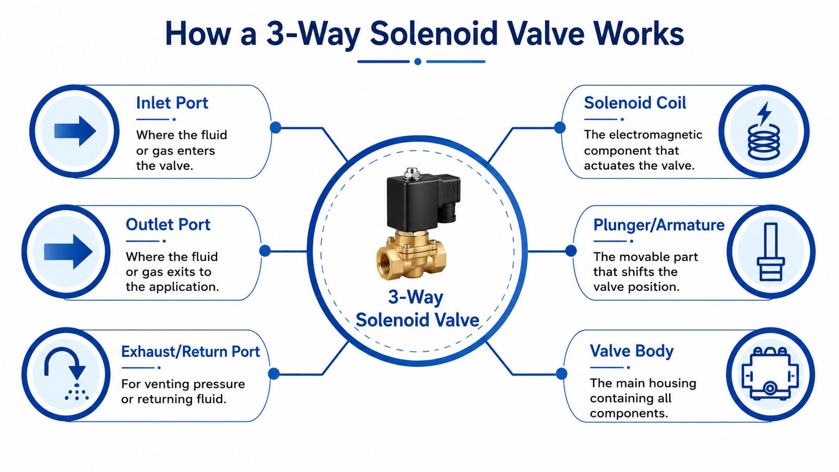
What the three ports actually do
The port names are simple. The consequences of getting them wrong are not.
- Inlet port takes system pressure or supply flow
- Outlet port goes to the working line, usually a cylinder port, clamp line, or pilot function
- Exhaust or return port vents air service or sends hydraulic oil back to tank
That third port is what changes the circuit behaviour. Tameson's overview of 3-way solenoid valves describes how the extra port allows the valve to divert or switch flow rather than just open and close a single passage. In practice, that is why 3-way valves suit single-acting actuators, latch functions, pressure release duties, and small control circuits where one line must be pressurised in one state and discharged in the other.
How the internal switching actually happens
Inside the valve, the coil generates a magnetic field when energised. That pulls the armature or plunger against a spring, and the sealing element shifts from one seat to another. One path opens. Another closes.
For a technician fault-finding at the machine, that basic motion matters more than the catalogue sketch. If the plunger is slow because of contamination, varnish, or weak coil pull, the valve may not switch cleanly. You then get partial opening, pressure drop, sluggish actuator movement, or a function that chatters before settling.
On a standard 3/2 arrangement, one position connects pressure to the outlet. The other connects the outlet to return or exhaust. The point to verify on every installation is the de-energised condition, because that determines what the machine does on power loss, broken wiring, or a blown fuse.
That is also where UK MRO teams often get caught. A replacement valve may match thread size and voltage but still reverse the safe state.
Carryover volume and fluid trapping
One practical issue that gets missed in many write-ups is carryover volume. In hydraulic service, the cavity between the sealing points, the outlet port, and the connected hose or manifold drilling can trap a small volume of oil during switching. On paper it looks minor. On a clamp, pilot line, or single-acting ram, it can delay release, leave residual pressure in the line, or cause a cylinder to creep instead of dropping away cleanly.
This matters most where the actuator has a small swept volume and the valve is mounted remotely from the load. A long hose between valve and cylinder increases the trapped oil volume, and the oil has nowhere useful to go until the return path is fully established. If fast pressure decay matters, keep the valve close to the actuator, minimise dead leg volume, and check whether the chosen spool or poppet geometry vents the outlet positively in the rest position.
For engineers comparing layouts, our guide to types of hydraulic valves is a useful reference point before you commit to a 3-way arrangement based only on its compact appearance.
Normally closed and normally open in practical terms
The usual choices are:
| Configuration | De-energised state | Typical practical use |
|---|---|---|
| Normally closed | Supply to outlet is blocked | Used where the function should stay off until commanded |
| Normally open | Supply is available to the outlet | Used where pressure should be present by default |
For hydraulic systems, that choice affects more than basic operation. It sets fail state, heat generation, and power draw. If a mobile power pack has to hold a valve energised for long periods, coil wattage starts to matter. We increasingly see OEMs asking for sub-5-watt valves on battery-supported or engine-driven packs because every continuous electrical load counts, especially on compact machines with limited alternator output.
A lower-power coil is attractive, but it comes with checks. Response time may be slower, magnetic pull is lower, and contamination tolerance can tighten up. That trade-off is manageable if the valve is sized properly, filtered properly, and used on a duty that does not demand aggressive switching under poor voltage conditions.
The same principle applies even on small utility circuits. If you need a compact replacement or want to buy 1/4 inch solenoid valve for a lighter-duty control function, the port pattern and de-energised flow path still need checking against the actual machine logic, not just the thread and coil label.
In service, the real question is simple. Which port connects to which, in the failed or de-energised state, and does that leave the machine in a safe and useful condition?
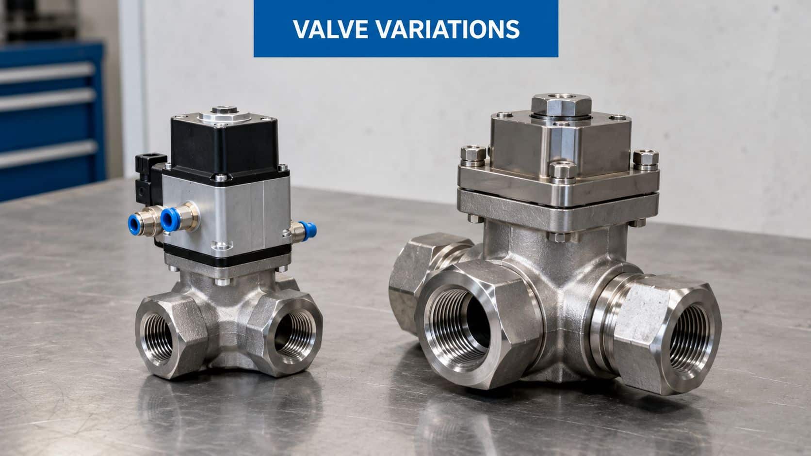
Exploring Valve Types and Key Variations
A 3-way valve that looks right on the bench can still create trouble once it is in a live hydraulic circuit. We see that regularly on UK service work. A replacement matches the ports and voltage, then starts trapping oil in a short branch line, leaves an actuator lazy on return, or keeps a small mobile power pack drawing more current than the OEM expected.
The first distinction is service type. Pneumatic 3-way valves are built around air flow, venting, and high cycle rates. Hydraulic versions need tighter leakage control, stronger bodies, and seal materials that hold up in oil, pressure spikes, and dirty service. That difference matters in MRO because a valve sold as a general 3-way solenoid valve may fit physically and still be wrong for the job.
Direct-acting versus pilot-operated
This is usually the first real selection fork.
Direct-acting valves move the sealing element with coil force alone. They suit low to moderate flows, zero-pressure switching, and compact manifolds where predictable behaviour matters more than maximum capacity. In fault-finding, they are also easier to diagnose because the coil either lifts the element or it does not.
Pilot-operated valves use the solenoid to open or close a pilot stage, then rely on system pressure to shift the main element. That helps when flow demand is higher or the valve package needs to stay compact for the duty. The trade-off is dependence on pressure conditions. If pressure is marginal, cold-start viscosity is high, or contamination reaches the pilot drilling, the valve can become inconsistent.
For UK OEMs building mobile power packs, that trade-off often overlaps with coil power draw. A low-energy valve can reduce continuous electrical load, but the margin for sticky internals and weak supply voltage gets smaller. On battery-supported or engine-driven packs, I would rather see a correctly sized direct-acting valve on a modest duty than a pilot-operated unit chosen only because the catalogue looked efficient.
Carryover volume also gets missed here. On some 3-way arrangements, the de-energised path leaves a pocket of trapped oil between the valve and actuator or pressure switch. That small trapped volume can hold residual pressure long enough to confuse diagnostics, delay movement, or keep a function partially loaded. In service, technicians often read that as a drifting cylinder, a sticky switch, or air in the line when the actual issue is the valve's port logic and the dead volume it leaves behind.
A simple selection check helps:
- Use direct-acting where the circuit must switch reliably at low or variable pressure, or where fast fault isolation matters.
- Use pilot-operated where system pressure is stable and the valve needs to pass more flow than a similar direct-acting body can handle.
- Check the de-energised flow path for trapped branches, especially on clamp, brake-release, and pilot dump circuits.
- Check coil wattage against duty cycle on mobile packs and any machine with limited charging capacity.
For engineers comparing layouts across a wider circuit, this guide to types of hydraulic valves helps place 3-way solenoid functions alongside the rest of the directional and pressure-control hardware.
Materials and application fit
Material choice decides service life. Brass bodies are common on lighter-duty fluid handling and utility equipment. Aluminium keeps weight down and suits many compact hydraulic assemblies, but it needs the right fluid compatibility and corrosion control. Seal choice matters just as much, particularly where machines see bio-oils, outdoor temperature swings, or long idle periods before a cold restart.
For MRO teams, a significant mistake is treating body material, seal material, and internal construction as secondary details. They are often the reason a replacement valve works for six months instead of six years. If a circuit has fine clearances, infrequent use, and contamination risk, a valve that is technically interchangeable can still give poor spool return, higher leakage, or sluggish response.
Packaging can also drive the decision more than expected in tight enclosures. Engineers sometimes compare compact product formats such as this buy 1/4 inch solenoid valve example to judge connection size, mounting space, and service access. It is not a hydraulic performance reference, but it is a useful reminder that envelope size, cable exit, and wrench clearance can decide whether a valve is practical to fit and maintain.
A valve that fits the manifold but leaves trapped oil, overheats the coil, or dislikes the fluid is still the wrong valve.
Decoding Key Technical Specifications
A valve arrives on site with the right port size, the right voltage on the coil label, and the right mounting pattern. It still leaves a mobile power pack running hot, traps oil in a branch line, or gives a single-acting actuator a lazy return. That usually comes back to three things on the datasheet that were skimmed instead of checked properly: pressure envelope, flow capacity, and coil duty.
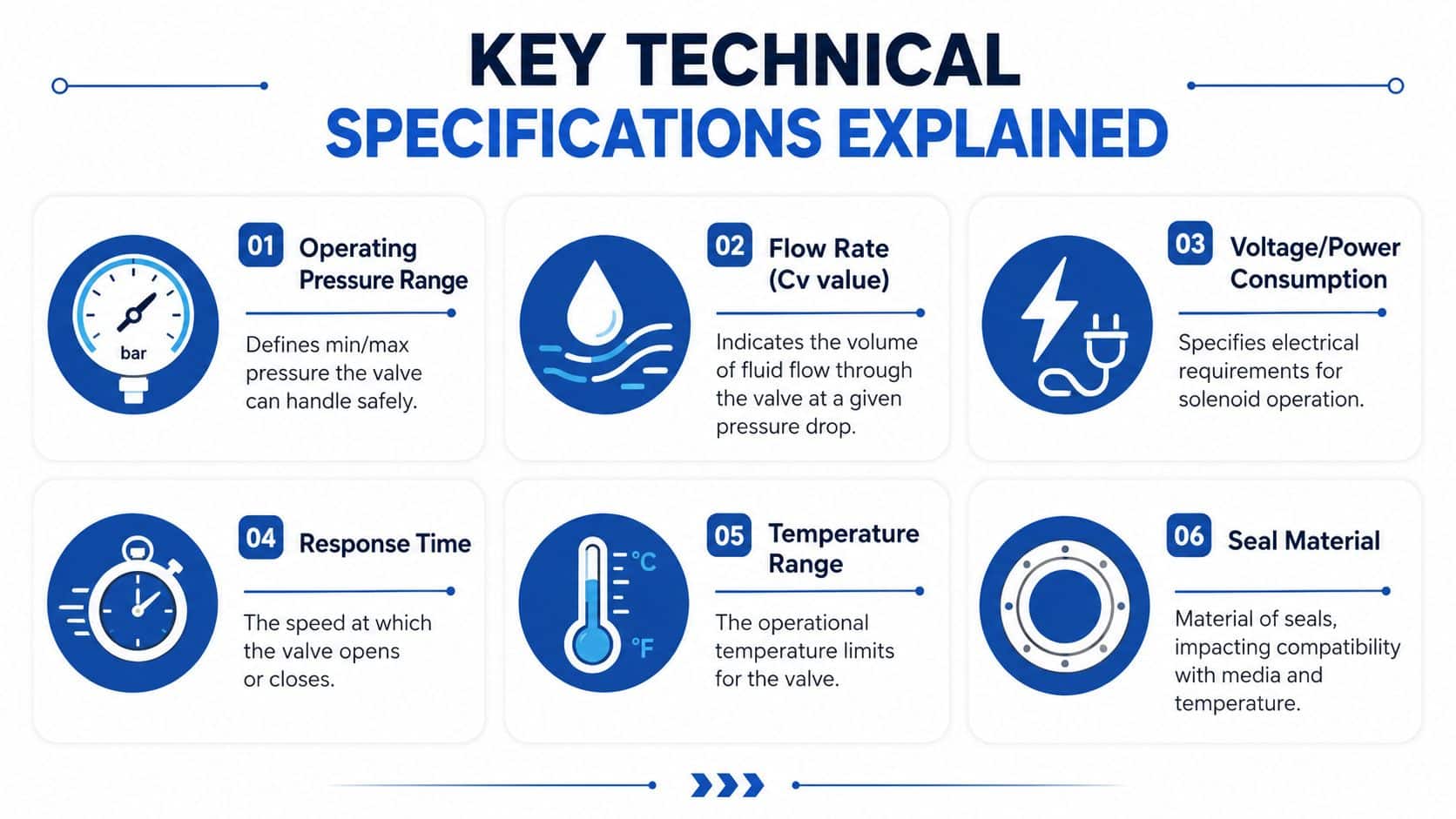
Pressure, flow and thread standard
Start with the actual circuit pressure, including transients, not just the nominal relief setting. A 3 way valve can survive the steady-state number on paper and still have a short life if pressure spikes hit it every shift. In hydraulic service, that matters more than catalogue shorthand.
Port thread and connection standard need the same discipline. UK MRO teams see this regularly with BSP, BSPP, and other thread forms mixed across older plant, imported skids, and manifold blocks. A valve that can be forced into place with adaptors is often the start of leaks, cracked ports, or poor service access six months later.
Then check flow capacity. Kv or the manufacturer's rated flow tells you whether the valve will pass oil without becoming the restriction in the line. If it is undersized, the machine often shows the fault somewhere else first. Clamp times drift out. A cylinder extends well enough but returns slowly. Pressure drop rises, oil heats up, and technicians start adjusting reliefs for a problem created by the valve selection.
Carryover volume deserves a place in this discussion too. On 3 way hydraulic circuits, especially around single-acting actuators, test points, and unload functions, the internal cavity volume and line routing can leave a small trapped oil pocket after switching. That trapped volume can hold residual pressure longer than expected, delay release, or give a false impression that an actuator or hose is still being fed. On compact OEM manifolds, reducing that dead volume often improves behaviour more than a small increase in nominal flow rating.
Coil voltage and power draw
Coil choice is not just an electrical item. It changes heat, power budget, and reliability.
For plant with a control panel and mains already available, AC coils can fit the architecture well. For mobile packs, battery-fed auxiliary hydraulics, and PLC-driven controls, DC coils are usually the better fit because they are easier to integrate and easier to protect. The wrong choice shows up as chatter, slow shifting, or a coil that runs hotter than the enclosure can tolerate.
Power draw deserves closer attention than it usually gets. On a fixed industrial machine, an extra few watts may not look important. On a mobile power pack or a compact OEM assembly, it can be the difference between acceptable battery drain and an avoidable parasitic load. We often steer designers toward sub-5-watt options where response time and force margin still suit the job, especially for hold-to-run functions or long energised periods. That is not always the right answer. Lower power coils can be less forgiving if supply voltage sags, wiring runs are long, or contamination raises the force needed to shift the spool.
A coil has to work with the actual duty cycle. Repeated short cycles in a warm enclosure can build heat faster than engineers expect.
Seals, body material and duty cycle
The practical checks are straightforward:
| Datasheet item | What it means in practice |
|---|---|
| Seal material | Must suit the fluid, temperature range, and idle periods without hardening or sticking |
| Body material | Must match corrosion exposure, weight target, and mechanical abuse in service |
| Duty cycle | Must match energised time and switching frequency, or coil temperature will climb too far |
Seal material is where many field problems start. A valve can be dimensionally correct and electrically correct, yet still give poor spool movement or internal leakage because the seals do not suit the oil, ambient conditions, or long standstill periods. That is a common issue on UK equipment that sits outside, starts cold, and then runs hard.
Body material is not just a corrosion decision either. Aluminium helps on mobile machinery where weight matters, but it needs sensible protection against salt, washdown, and thread damage from repeated maintenance. Brass and steel bodies may add weight, but they can be the better choice where fittings are changed often or the valve lives in a harsher mechanical environment.
Workshop note: If a 3 way valve is running hotter than expected, check coil duty, enclosure temperature, supply voltage at the coil, and whether trapped pressure is forcing the internals to work harder on each shift.
Selecting the Right Valve for Your Application
A common service call goes like this. The ram retracts slowly, the power pack runs warmer than expected, and nothing looks obviously wrong until you find a small trapped volume sitting between the valve and actuator. The valve is technically the right size and pressure rating, but it is the wrong arrangement for the circuit behaviour the machine needs.
Start with the machine state table. Define what each port must do in the energised state, the de-energised state, and during a power loss. On 3-way circuits, that step prevents a lot of expensive guesswork, especially on OEM builds where a valve chosen for simple on-off control later ends up managing venting, hold pressure, or bypass flow as well.
For a single-acting ram, clamp, or spring-return actuator, a 3/2 valve is often the cleanest answer because it can alternate between pressure and exhaust without extra valving. The real selection point is not only normally closed versus normally open. It is whether the rest state leaves a pocket of oil trapped in the work line. If carryover volume is left sitting under load or heat, the actuator can creep, pressure can rise locally, and maintenance teams end up chasing a fault that looks intermittent.
For diverting or bypass duty, check the default flow path against the machine's safe state and thermal behaviour. Some compact hydraulic power packs need the line dumped in the rest state to limit heat and reduce parasitic load on the pump. Others need the service line available immediately at startup. That decision affects response, standby losses, and what happens after an electrical dropout.
For hazardous areas, use a valve with the right certification for the site classification and the installed electrical hardware. UK agricultural, waste-handling, and bulk materials equipment often sits in dusty environments where enclosure choice, connector sealing, and cable routing matter as much as the valve body itself.
Low-power coils deserve more attention than they usually get. On mobile power packs and battery-supported equipment, sub-5-watt valves can cut standing electrical load and help with thermal management inside a tight enclosure. The trade-off is actuation margin. A low-power coil that shifts perfectly on a bench can become marginal on a cold morning with long cable runs, reduced system voltage, sticky contamination, or spool drag from poor oil condition.
I usually check these points before signing off a valve choice:
- Fail state. Confirm the safe hydraulic condition on loss of power, not just the normal operating condition.
- Carryover volume. Check whether the porting arrangement traps oil where the circuit really needs a clean vent or relief path.
- Available voltage at the coil. Measure it at the valve under load, especially on mobile machines and long harness runs.
- Pressure drop in service. A valve can shift correctly and still cause sluggish actuator movement or heat because the flow path is too restrictive.
- Power draw versus shift reliability. Sub-5-watt coils suit many compact units, but only if the installed circuit still gives dependable pull-in and return.
- Maintainability. Thread form, connector type, manual override access, and replacement lead time all matter to UK MRO teams trying to keep downtime short.
Selection errors often show up later as nuisance faults rather than obvious mismatches. If a circuit has unexplained drift, heat, or inconsistent actuator behaviour, it is worth reviewing the valve logic and trapped-volume paths before replacing parts. Our guide to common hydraulic valve problems covers the fault patterns that usually point back to a poor valve choice rather than a failed component.
Troubleshooting Common 3 Way Valve Faults
Most 3-way valve faults don't start as complete failures. They start as intermittent shifting, sluggish return, heat build-up, or an actuator that doesn't behave the same way twice. Good fault-finding means separating the electrical issue from the hydraulic one, then checking whether the valve is at fault or only exposing a wider circuit problem.
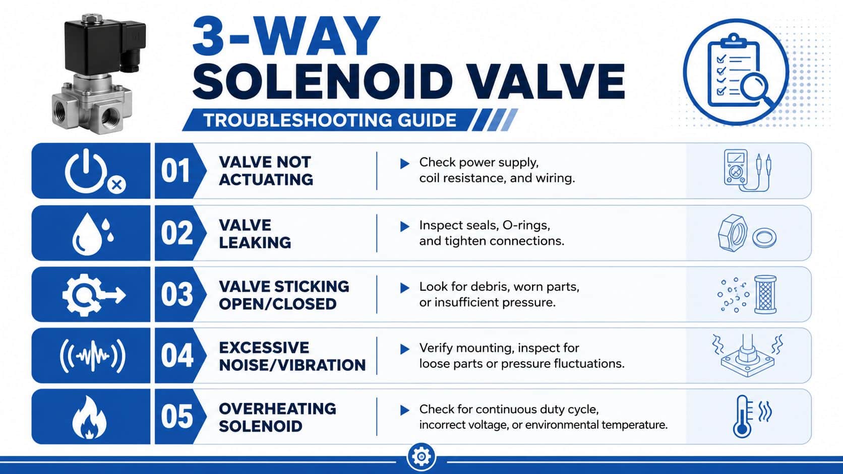
Fault symptoms and likely causes
| Symptom | Likely cause | Practical action |
|---|---|---|
| Valve won’t shift | Wrong supply voltage, damaged coil, wiring fault, contamination, sticking internals | Verify electrical supply, inspect wiring, test the coil, then inspect for debris or mechanical sticking |
| Valve leaks internally | Worn seals, contamination, damaged seat, wrong fluid compatibility | Check fluid condition, inspect seals and seat faces, confirm material compatibility |
| Valve leaks externally | Loose fitting, damaged O-ring, cracked housing, thread mismatch | Re-check sealing faces, fitting condition, and thread type |
| Coil runs hot | Wrong voltage, unsuitable duty cycle, continuous energisation, poor heat dissipation | Confirm the coil specification and operating cycle |
| Actuator behaves erratically | Restriction, unstable switching, trapped fluid, partial blockage | Inspect the circuit path, not just the valve body |
If you're working through repeated system faults, this guide to hydraulic valve problems is worth keeping nearby because it helps separate valve issues from pressure, contamination, and installation errors elsewhere in the system.
The overlooked carryover volume problem
One issue that gets missed far too often is carryover volume. The Lee Company discussion of selection issues in 3-way valves points out that a small amount of fluid can become trapped between flow paths when the valve shifts. In hydraulic service, that trapped slug can migrate and create contamination problems.
This matters in mobile and agricultural machinery more than many maintenance guides admit. If you're dealing with fluid integrity concerns, especially where one path must stay cleaner than another, this failure mode deserves attention.
Don't assume cross-contamination always comes from the reservoir or a hose change. Sometimes the valve itself is carrying a small trapped volume between states.
What usually works in the field
The mitigation approach depends on the circuit, but these checks are worthwhile:
- Review the valve's internal routing rather than relying on the external port labels alone.
- Check whether the application can tolerate trapped fluid when the valve shifts.
- Flush and sample fluid intelligently if contamination appears localised to a switching function.
- Reconsider the valve type if fluid segregation is critical and the current arrangement keeps carrying over residue.
The valves that cause the most frustration are often the ones that still energise and click normally. That audible click proves very little. It only tells you the coil moved something.
Sourcing and Installing Your Solenoid Valve
Procurement usually starts with a part number, but the better approach is to confirm the part number and the valve function together. A visually similar 3-way valve can have a different default state, different seal materials, or a different coil rating. That's how expensive mistakes get fitted with confidence.
For UK buyers, a real benchmark helps. A genuine Parker 3-way solenoid valve, part code 632018/22, has been listed at approximately £62.34 ex-VAT with a 10–14 day lead time in the UK market, according to this Parker valve listing. There's also a UK-market example of a 3-way Parker solenoid valve with a 220/240V coil and 9W power consumption priced at £62.00 including tax from this UK product listing. Those figures aren't a universal market rate, but they're useful for budgeting and planning.
Before installation, keep the checklist tight:
- Confirm thread form. BSP compatibility matters on UK systems.
- Match coil voltage exactly to the machine supply and control method.
- Check port identification against the actual hydraulic function.
- Inspect cleanliness of hoses, manifolds, and adaptors before fitting.
- Review commissioning steps rather than energising and hoping for the best. A proper commissioning procedure for hydraulic systems saves rework.
A correct installation is usually quiet, uneventful, and slightly boring. That's the target.
If you need help identifying, cross-referencing, sourcing, or specifying the right valve, contact MA Hydraulics Ltd. For practical advice on mobile and industrial hydraulic applications, Phone 01724 279508 today, or send us a message.
