Pump cavitation is a damaging process where low pressure at the pump inlet causes vapour bubbles to form in the hydraulic fluid and then violently collapse, eroding internal components. In practical terms, cavitation starts when NPSHa falls below NPSHr, and accepted industry monitoring has long treated a 3% drop in pump head as the onset point in traditional centrifugal pump assessment.
If you're reading this after hearing a pump turn rough, sharp or gravelly, you're already in the right place. Most engineers first meet cavitation by sound, not by calculation. A machine that ran cleanly yesterday suddenly sounds wrong today, and if nobody acts quickly, that noise turns into scored surfaces, damaged gears, seal issues and an avoidable strip-down.
In UK mobile and industrial hydraulics, cavitation isn't just a textbook issue. It shows up on power packs with awkward tank layouts, agricultural machinery started on cold oil, compact units with over-restricted suction plumbing, and systems where someone added a suction filter thinking it was a safe upgrade. The damage pattern is predictable. The causes usually are too.
That Sound Your Hydraulic Pump Should Never Make
Most maintenance teams know the sound straight away. It isn't a normal hydraulic whine and it isn't the steady note of a loaded pump. It's harsher than that. Operators often describe it as marbles, gravel or a dry rattling noise coming from the pump body.
That sound matters because what is pump cavitation isn't just “a noisy pump”. It's a pressure problem on the inlet side that turns into mechanical damage inside the pump. By the time the noise is obvious, the pump may already be eroding itself.
I've seen this misread as bearing noise, air ingress, or “a tired unit”. Sometimes those faults are present too. But if the pump has started making a rough crackling sound and performance has become inconsistent, cavitation needs checking early, not after the next failure.
What the workshop usually sees first
In real plant conditions, the first clues tend to come in a cluster:
- Noise change: A sudden harsh rattle rather than the usual smooth running note.
- Erratic operation: Actuators feel uneven or slower under load.
- Heat rise: The unit runs hotter because the pump isn't being fed cleanly.
- Repeat failures: New pumps don't last because the system fault was never removed.
A useful comparison comes from other fluid-based heating and pumping systems too. If you're interested in how pressure, temperature and system layout interact in a different application, this Sydney heat pump hot water guide is a sensible read because it shows how installation details shape performance long before faults become obvious.
Practical rule: If the noise appeared after a hose change, filter change, oil change or relocation of the tank, start on the suction side first.
Noise control matters, but silencing the symptom isn't the same as curing the fault. If you're dealing with broader hydraulic sound issues as well as cavitation diagnosis, noise reduction techniques for hydraulic systems can help separate normal hydraulic noise from destructive inlet-side problems.
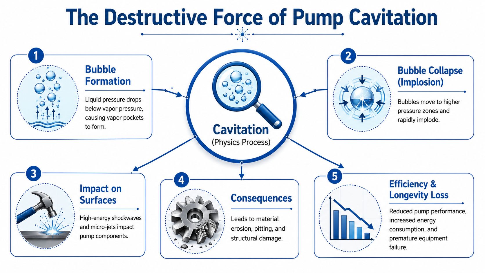
The Destructive Force of Pump Cavitation
Cavitation is simple physics with ugly consequences. Pressure at the pump inlet drops so far that the fluid can no longer remain fully liquid. Vapour pockets form, travel into a higher-pressure region, then collapse violently against metal surfaces.
What actually happens inside the pump
A simple way to think about it is boiling without heat. Liquid doesn't only boil because temperature rises. It can also “boil” because pressure falls. On the suction side of a pump, local pressure can drop below the fluid's vapour pressure, and that is where the trouble starts.
The recognised engineering description is clear. Pump cavitation begins when Net Positive Suction Head Available is lower than Net Positive Suction Head Required, allowing pressure at the impeller inlet to fall below vapour pressure. The bubbles then collapse in higher-pressure zones and can strike metal with micro-jets exceeding 1000 bar, while BS EN 12723 sets a safety margin of at least 0.91 m above NPSHr to prevent cavitation in relevant hydraulic applications, as outlined by Armstrong Fluid Technology on pump cavitation and system damage.
Why small bubbles do so much damage
The bubble itself isn't the problem. The collapse is. When that vapour pocket implodes, the force concentrates onto a tiny area of metal. Repeated often enough, that impact pits surfaces, strips protective finishes and roughens edges that need to stay smooth for proper flow.
In centrifugal pumps, the damage often appears around impeller inlets and vane surfaces. In hydraulic gear and other positive displacement arrangements, the same pressure starvation still creates destructive inlet-side effects. Once the metal surface is roughened, flow gets worse. The pump then becomes even more vulnerable to further cavitation.
A cavitating pump can still run. That's what makes it dangerous. People keep operating it while the internal surfaces are being hammered.
Why engineers treat it as urgent
The damage pattern isn't limited to metal loss. Cavitation also drives vibration, destabilises output and shortens the life of seals, bearings and couplings connected to the unit. A pump may survive for a while, but it won't stay healthy.
That is why experienced engineers don't dismiss a rough-running inlet side as a minor annoyance. Cavitation is one of those faults where delay nearly always costs more than early correction.
How to Spot the Symptoms of Cavitation
The earliest warning is often audible, but relying on sound alone isn't enough. By the time a person can clearly hear cavitation, the pump has usually been under stress for some time.
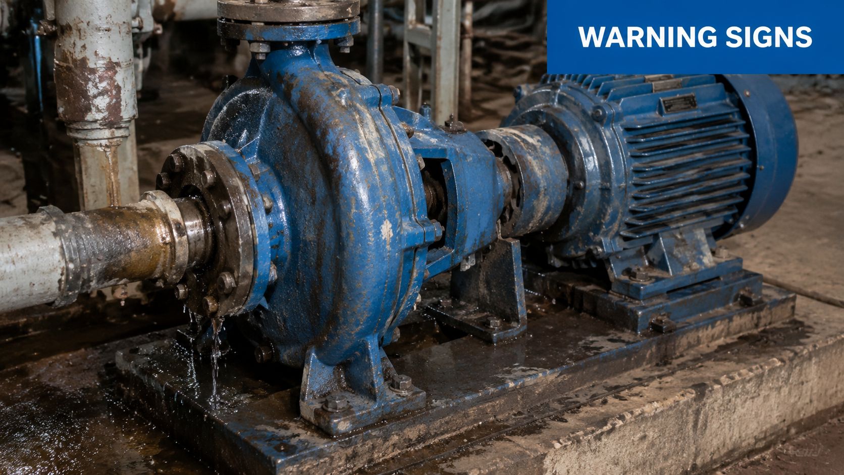
What operators notice on the machine
The classic symptom list is practical rather than theoretical:
- Harsh rattling noise: Often described as gravel or marbles in the pump.
- Higher vibration: The unit feels rougher through the frame, pipework or mounting.
- Reduced output: Flow or pressure no longer matches the machine's normal response.
- Temperature creep: The system runs warmer because the pump is working badly.
- Intermittent behaviour: The fault may worsen as oil temperature or demand changes.
One of the most useful cross-checks is to compare the symptom with the system condition at start-up and after warm-up. If the machine is markedly worse on cold mornings, fluid condition and suction losses deserve close attention.
For a structured condition-monitoring approach, hydraulic vibration analysis guidance is worth using alongside direct pressure checks and physical inspection.
What good diagnostics look like now
Listening still has value. A skilled fitter can often tell when a pump sounds wrong. But modern maintenance teams are moving beyond ears and guesswork. According to Armoloy's review of cavitation causes, effects and solutions, 40% of UK industrial maintenance teams now use ultrasonic cavitation detectors and real-time pressure monitors, with reported reductions in cavitation-related downtime of up to 35%.
That shift matters because ultrasonic tools can detect the high-frequency signature of bubble collapse before the noise becomes obvious to operators. Pressure monitoring also shows whether inlet conditions are drifting toward a fault state.
A useful visual explainer is below if you want to compare audible symptoms with mechanical behaviour in service.
When symptoms are easy to misread
Cavitation gets confused with aeration all the time. Both create noise, poor response and damage risk. The difference is important. Aeration means air is entering the fluid. Cavitation means the fluid itself is vapourising because inlet pressure has fallen too low.
If the pump is noisy and the suction side has recently been modified, measure before you replace. Too many pumps get condemned when the real problem is still bolted to the machine.
That habit alone saves a lot of wasted parts and repeat breakdowns.
Common Causes of Cavitation in Hydraulic Systems
Cavitation usually starts upstream of the pump, in the inlet arrangement, not inside the rotating group itself. In practice, the trouble is nearly always created by restriction, poor layout, unsuitable hose, fluid condition, or several small faults stacking up until the pump runs short of oil.
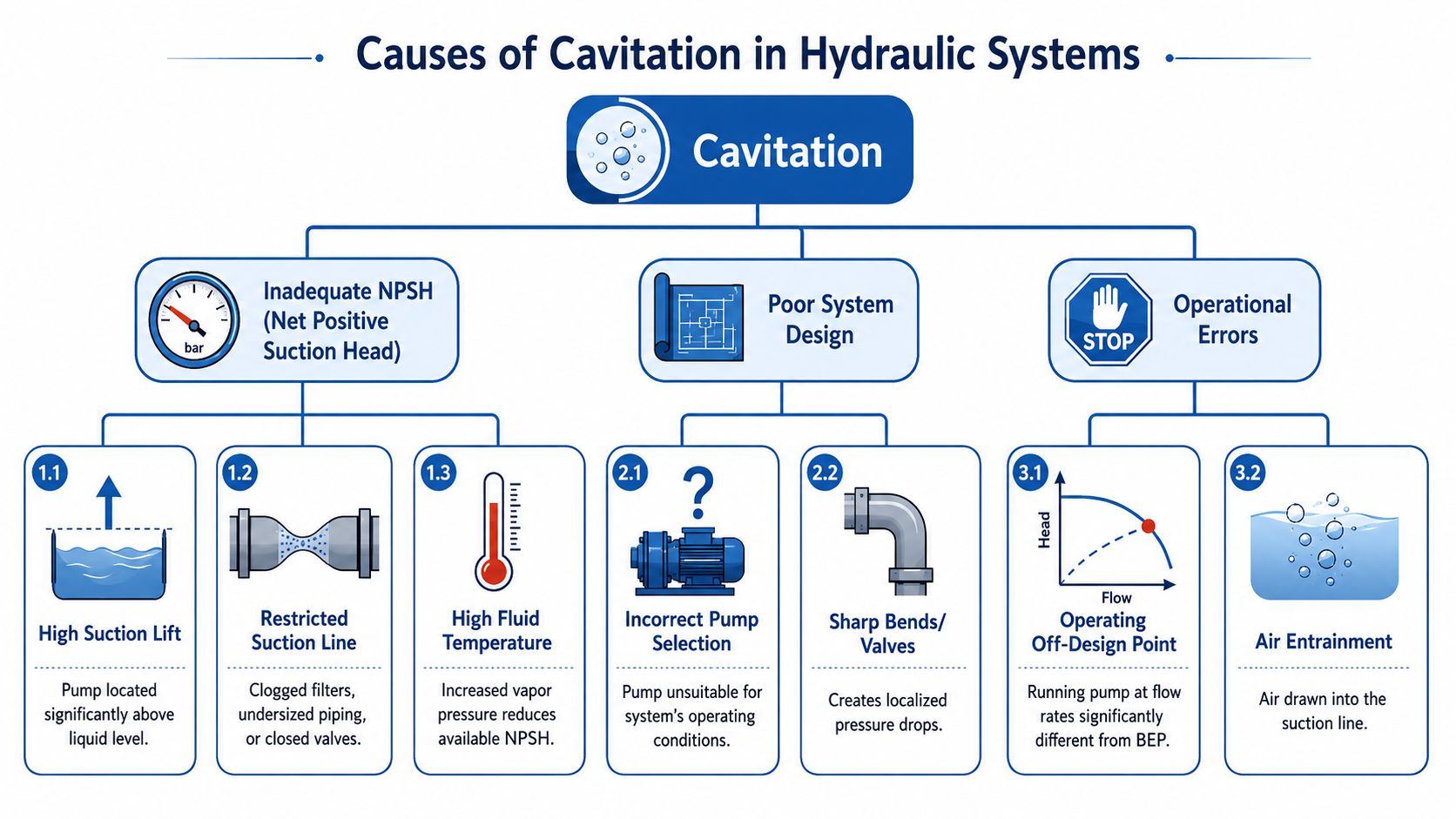
Inlet restriction is usually the starting point
Across mobile plant and industrial power packs, excessive vacuum at the pump inlet is the mechanism that matters. Flowfit's explanation of hydraulic pump cavitation causes and symptoms points to poor suction plumbing as a frequent cause, and that aligns with what turns up on site.
The repeat offenders are familiar. Suction lines are too long. Bores are too small. Elbows and reducers are added to solve packaging problems. Tank outlet ports look acceptable on a drawing, then prove restrictive at cold start or full demand. None of those faults looks dramatic in isolation. Together, they pull inlet pressure down far enough for the oil to vapourise.
Flow demand matters here as well. If the pump has been upsized, speed has increased, or duty has changed, an inlet line that was once serviceable can become marginal. That is why hydraulic flow rate calculations for pumps and circuits should be checked against the actual operating condition, not just the original build spec.
Filtration is a common self-inflicted problem
The suction-side filter catches many teams out. It gets fitted to protect the pump, then becomes the very restriction that starves it. The risk rises further once the element starts to load with contamination or the oil is cold and thick.
Return-line or pressure-line filtration is often the better arrangement because the pump does not have to pull through the element. That is not a blanket rule. Some systems do need inlet strainers or coarse suction protection. The point is selection and placement. A fine element on the suction side is often poor engineering.
A clean filter in the wrong place can still starve a pump.
This is one of the more overlooked causes on UK machinery because the machine may run acceptably for months, then start complaining in winter or after a service interval when the wrong element grade has been fitted.
Suction hose choice is not interchangeable
A suction line needs hose built to resist collapse under vacuum. Muncie Power's guide to hydraulic pump cavitation and correct suction hose selection explains why specifications such as 100R4 or SAER4 matter on inlet duty.
This gets missed on breakdown repairs. A general-purpose hose with a similar bore may fit the couplings and look fine externally, but if it softens or necks down under demand, the restriction is already there. The pump sees the pressure loss immediately. The fitter often sees nothing until the hose is removed and inspected.
Oil viscosity changes the picture, especially in UK weather
In British conditions, viscosity is often the factor that turns a marginal inlet into a failed one. Cold morning starts on agricultural kit, telehandlers, compact plant and outdoor power units raise suction losses sharply. A machine that behaves in July can cavitate in January without any hardware change.
Command Hydraulics' article on cavitation in hydraulic pumps gives a UK-specific example from Scunthorpe, North Lincolnshire, showing how heavier oil grades in winter can push pressure drop across a strainer high enough to cause trouble.
That trade-off needs handling properly. A heavier oil may suit wear control or summer operating temperature, but if it cannot reach the pump cleanly during cold start, the pump still pays the price.
Layout decisions often create the fault quietly
A few design choices show up repeatedly on problem installations:
- Undersized suction line. Material cost is saved, pressure loss goes up.
- Excessive line length. Every extra metre adds friction loss.
- Reservoir level below the pump. Static head is reduced, especially at low tank level.
- Too many fittings. Bends, valves and reducers each add inlet loss.
- Poor tank outlet design. Internal standpipes, small ports or awkward pickup positions restrict supply.
- Modified pipework after commissioning. Field changes often introduce losses that were never recalculated.
Modern diagnostics help here. Ultrasonic and pressure tools can show that inlet conditions are deteriorating, but the correction is usually mechanical. Shorter runs, larger bore, the right hose, the right filtration arrangement, and oil viscosity matched to the season. Those decisions make the difference between a pump that survives on paper and one that survives in service.
Understanding and Calculating NPSH
If you want to diagnose cavitation properly, you need to separate pump characteristics from installation characteristics. That is exactly what NPSHr and NPSHa do.
NPSHr belongs to the pump. The manufacturer specifies how much suction head the pump needs at a given operating point.
NPSHa belongs to the system. It reflects what the installation can deliver to the pump after height effects, fluid condition and line losses have all taken their share.
The relationship that matters
Cavitation starts when NPSHa is lower than NPSHr, and one engineering standard approach is to build in a margin so that NPSHa is at least 1.5 metres greater than NPSHr for reliable operation, as discussed in Frontiers in Energy Research on cavitation monitoring and NPSH safety margin.
That margin is where many practical systems fail. The nominal calculation may look acceptable on paper, but once you account for cold oil, a restrictive hose, a dirty element or a tank level lower than expected, the margin disappears.
A simple way to estimate NPSHa
For a typical hydraulic power pack, the estimate is straightforward in principle:
- Start with the static head available from the reservoir position relative to the pump.
- Account for the fluid condition and inlet arrangement.
- Subtract friction losses in the suction hose, fittings, valves and any strainers or filters.
- Compare the result with the pump's NPSHr.
- Keep a real safety margin. Don't design to the edge.
If the reservoir is above the pump, the system gets some help from positive head. If the reservoir is below the pump, losses become much harder to tolerate and suction plumbing has to be exceptionally clean and short.
For engineers working through related sizing work on compact and industrial hydraulic systems, flow rate calculations for hydraulic applications are part of the same discipline because flow, line size and pressure loss all interact.
A practical design mindset
In workshop terms, NPSH isn't an academic number. It's a way of asking one simple question. Can the oil reach the pump easily enough under the worst real operating condition?
That means checking more than the nominal running point:
- Cold-start condition
- Lowest tank level
- Highest expected flow demand
- Most restrictive likely filter or strainer condition
- Fluid viscosity used on site
Design for the worst credible suction condition, not the best-case commissioning day.
Once engineers adopt that habit, cavitation faults become much less mysterious.
Proven Strategies to Prevent Pump Cavitation
Prevention is nearly always cheaper than replacing pumps, flushing contaminated circuits and dealing with repeat stoppages. The fixes aren't glamorous, but they work when applied properly.
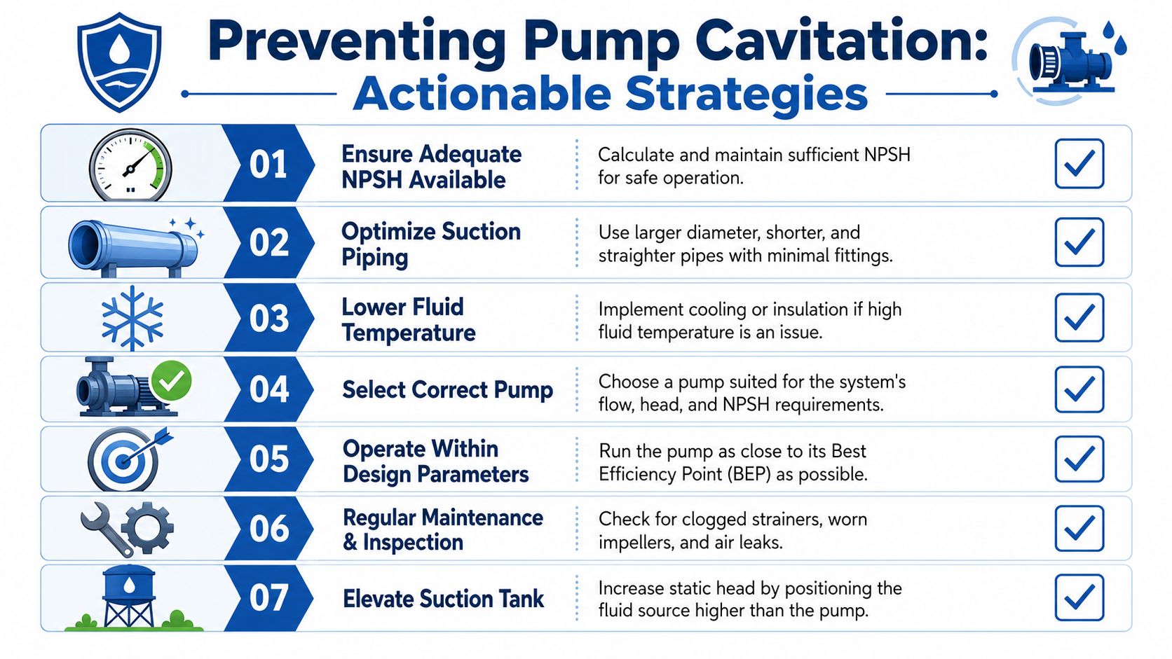
Start with the inlet side
The most reliable rule of thumb is to maintain inlet pressure at 10% greater than the pump's specified NPSHr. Practical corrective actions include slowing pump speed and increasing the inlet pipe diameter by one to two standard sizes larger than the outlet, as set out in CSI Designs' guidance on pump cavitation prevention and NPSH margin.
Those measures work because they attack the root issue. More inlet margin means less vapour formation risk. Lower speed reduces the pump's suction demand. A larger inlet line reduces friction loss before the fluid reaches the pump.
Design changes that usually pay off
Some fixes are simple and highly effective:
- Shorten the suction run: Keep the pump close to the reservoir where possible.
- Use a larger inlet line: The suction side should not be treated like a standard pressure line.
- Reduce fittings: Every elbow, reducer and restrictive valve costs pressure.
- Position the tank well: Positive head helps. In some plant arrangements, locating the supply above the pump is a very practical answer.
- Choose the correct hose type: A suction hose must resist collapse and maintain section under vacuum.
Where a system has persistent cavitation that only appears at high demand, reducing pump speed can be the cleanest answer. It may not be the first fix people want to hear, but if the machine doesn't need the original speed, slowing the unit often stabilises the inlet condition immediately.
Maintenance changes that stop repeat failures
Prevention isn't only for new designs. Existing machines can often be improved quickly by changing service habits:
- Move filtration downstream where practical: Don't force the pump to pull through unnecessary restriction.
- Check oil grade for seasonal use: UK winter operation can expose viscosity problems that stay hidden in warm conditions.
- Inspect tank breathers and levels: A starved reservoir condition can mimic more complex faults.
- Review every replacement part on the suction side: A “close enough” hose or fitting often isn't.
A common trap is replacing the failed pump and nothing else. If the root cause sits in the suction layout, the new pump enters the same bad environment and starts deteriorating again.
What doesn't work
People sometimes try to solve cavitation indirectly. They add acoustic insulation, fit another pump, or assume the fault is just wear. None of that restores inlet pressure.
The effective approach is to remove restriction, control viscosity, preserve suction margin and operate the pump within conditions it can tolerate.
Ensuring Long-Term Pump Reliability
A pump that runs smoothly through a cold UK morning start, then holds pressure and response once the oil is warm, is usually a pump with its basics right. The suction side is free enough, the fluid grade suits the season, filtration has been positioned with some thought, and the inlet condition has been checked under real duty rather than workshop assumptions.
Over the long term, cavitation nearly always points back to something specific. I see the same patterns repeatedly in field work. A suction strainer added with good intentions but too much restriction. A replacement hose that looks correct but pulls flat under demand. Oil that is acceptable in summer and too thick on a winter start in Lincolnshire, Yorkshire, or further north. None of those faults are dramatic on day one, but they steadily shorten pump life.
Reliable plants and mobile machines do not rely on noise alone. Maintenance teams get better results when they trend case drain condition, inlet vacuum, temperature, vibration, and filter differential pressure together. That approach catches developing inlet problems earlier, especially on machines where the operator only notices the fault once performance has already dropped.
There is also a broader engineering point here. Surface protection and wear control matter across many mechanical systems, and the benefits of graphene technology show how material-focused solutions are being examined in other high-wear applications. Hydraulic pumps still live or die by inlet conditions first, but good engineers should keep an eye on adjacent developments.
If a pump has gone noisy, output has fallen away, or a suction layout looks marginal on review, get a second technical opinion before fitting another unit. That is usually cheaper than repeating the same failure with a new pump.
