
You're usually looking at accumulator sizing when something in the machine already feels wrong. The press hesitates on peak demand. The mobile circuit gets harsh pressure spikes. A pump that should have had an easy life is running hotter and wearing faster than expected. In plenty of UK systems, the accumulator isn't absent. It's just badly specified.
That's why hydraulic accumulator sizing matters so much. It sits at the junction of performance, reliability, service life and safety. Get it too small and it won't deliver the usable oil volume the circuit needs. Go too large and you've paid for vessel volume, space claim and pipework that may never earn its keep, while also risking a sluggish response in the wrong application.
The trap is that many sizing guides stop at the maths. Real jobs don't. A good accumulator choice has to survive the duty cycle, suit the mounting position, tolerate the fluid and temperature range, and still pass procurement checks in the UK.
Why Accurate Accumulator Sizing Matters
A hydraulic accumulator is often asked to do one of four jobs. Store energy, absorb shock, smooth pulsation, or support flow when the pump can't react quickly enough. If you size for the wrong job, the system tells you very quickly.
An undersized unit usually shows up as unstable pressure and disappointing support during the part of the cycle that matters most. An oversized unit creates a different set of problems. It takes up room, adds cost, and can leave the designer thinking the circuit is protected when the actual installation and pre-charge settings say otherwise.
The practical consequence is that accumulator sizing is never just a paper exercise. It affects pump loading, valve response, cylinder behaviour and how the machine feels in service. In motion-control and closed-loop systems, that matters even more because the accumulator is often there to steady pressure while the pump and control hardware catch up.
A mathematically neat answer isn't enough if the machine still hunts, bangs, or sags in operation.
There's also a procurement issue. In the UK market, engineers and buyers often finish the sizing calculation first, then realise they still need a compliant, documented, site-acceptable pressure component. That's one reason so many replacement purchases go wrong.
If you want a quick refresher on the component's role before getting into sizing detail, MA Hydraulics has a useful guide on what accumulators do.
Gathering Your Essential System Data
Before you touch a gas-law calculation, collect the operating data properly. Most bad accumulator selections start here, not in the formula. Someone guesses the pressure band, uses nominal pump flow instead of actual demand, or ignores how the machine really cycles.
Start with the three values that drive the calculation
For practical hydraulic accumulator sizing, define these first:
- Minimum system pressure. This is the lowest pressure at which the circuit must still do the job properly.
- Maximum system pressure. This is the highest normal operating pressure the accumulator will see during charging.
- Required usable fluid volume. This is the volume of oil the accumulator must deliver between those two pressure points.
Those three values are the backbone of the sizing exercise. If one is wrong, the rest of the result is wrong.
On an industrial power pack, the usable fluid volume often comes from a short period of demand where actuator flow exceeds pump flow. On a mobile machine, it may come from an emergency function, boom suspension requirement, or a need to cushion a transient event without letting pressure collapse.
Duty cycle matters more than people expect
Don't just ask what the pressure is. Ask when it is, and for how long. The cycle time tells you whether the gas behaves more like a rapid compression event or a slow one with time to exchange heat.
That's why I always want to see a simple duty-cycle note alongside the pressures. A crude sketch with charge, hold and discharge periods is better than a polished but incomplete spreadsheet.
If you're deriving oil demand from actuator speed and area, get the flow right before you get the accumulator right. A good companion reference is this MA Hydraulics page on flow rate calculations.
Don't ignore temperature, fluid and layout
Temperature affects gas behaviour, and fluid choice affects seal compatibility and service life. Even when the basic volume calculation looks straightforward, the installation environment can make a sensible theoretical size perform poorly in the field.
Use a pre-calculation checklist like this:
| Item | What to confirm |
|---|---|
| Pressure band | Actual minimum and maximum working pressure, not relief setting guesswork |
| Oil volume needed | Real delivered volume during the event being supported |
| Cycle speed | Fast cycling or slow cycling |
| Operating temperature | Expected ambient and running conditions |
| Hydraulic fluid | Mineral oil or another fluid requiring different seal materials |
| Installation point | Distance from the valves or point of demand |
| Maintenance access | Whether pre-charge checks can be done easily |
Practical rule: If the data has come from memory, not from the machine record, pressure trace, or duty review, treat it as unverified.
One more point that often gets missed in UK service work. Replacement jobs rarely happen under ideal conditions. Ambient conditions vary, maintenance intervals vary, and the machine may not be running exactly as originally designed. That's why clean data collection at the start saves a lot of grief later.
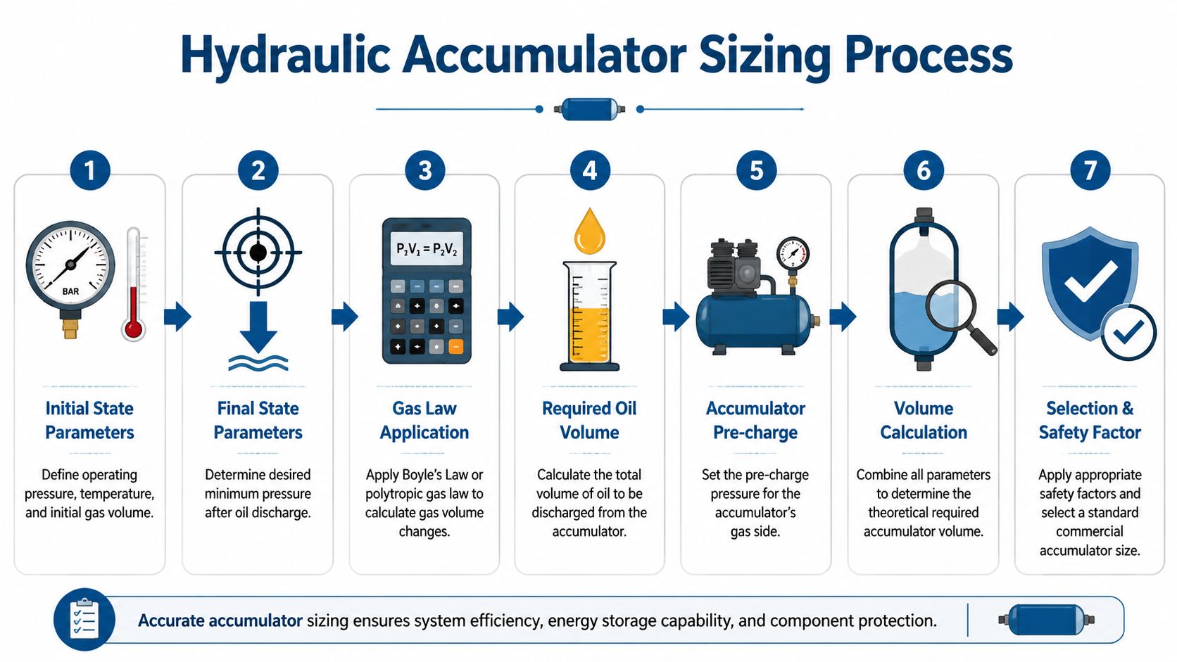
The Core Sizing Calculation Explained
The basic calculation uses the gas law approach. In plain terms, the accumulator stores hydraulic energy by compressing gas, so your sizing method has to reflect how that gas volume changes between minimum and maximum system pressure.
A practical approach for UK hydraulic system design is to define the minimum system pressure, maximum system pressure, and required usable fluid volume, then calculate the total accumulator volume and set pre-charge at about 80 to 90% of minimum system pressure. For rapid cycling, adiabatic behaviour is typically assumed, while slower cycles can use isothermal assumptions. Guidance also recommends oversizing by 10 to 20% to cover temperature variation, gas permeation, and performance drift over time, which is a useful field margin in UK conditions where ambient temperature and maintenance intervals vary (Firgelli guidance on accumulator sizing).
What the variables mean in practice
The maths is simpler when you attach each variable to a machine reality:
- Minimum pressure is the point below which the function is no longer acceptable.
- Maximum pressure is the top of the accumulator charging range in normal service.
- Usable fluid volume is the oil you need the accumulator to give back.
- Pre-charge pressure is the nitrogen charge set before the hydraulic side is pressurised.
- Total accumulator volume is the shell size you'll eventually buy.
The trap is treating these as abstract symbols. They aren't. They're direct expressions of machine behaviour.
Isothermal or adiabatic
This choice changes the result. It shouldn't be guessed.
Technical guidance warns against using an adiabatic calculation for cycles longer than about one minute, because that can give an overly conservative answer and make the accumulator appear larger than necessary. The same guidance notes that adiabatic equations are intended for rapid charge and discharge applications under one minute, while longer cycles need a thermodynamic assumption matched to actual heat transfer. It also notes that accumulators should be installed near the valves or point of demand to reduce pressure loss and preserve response time, and that setting pre-charge too low reduces effective gas volume and causes larger pressure swings (Coastal Hydraulics accumulator sizing guidance).
In day-to-day terms:
- Rapid cycling usually means use an adiabatic assumption.
- Slow cycling usually means an isothermal assumption is closer to reality.
- Long dwell periods need extra care because the gas has time to exchange heat with its surroundings.
That distinction is one of the most common reasons two engineers produce different sizes from the same pressure data.
A useful parallel exists in other fluid systems. If you ever need a refresher on how demand-side calculations are built from actual flow conditions, these water flow rate calculation methods are worth a look because they reinforce the same engineering habit: calculate from the job the system must do, not from a rough nameplate figure.
Later in a design review, I'd rather defend a well-chosen thermodynamic assumption than a neat but generic formula copied from a calculator.
Pre-charge and margin
Pre-charge is where many installations go off course. Too low, and the gas side doesn't occupy enough of the useful operating range. The accumulator still exists physically, but you've reduced the effective working volume and increased pressure fluctuation.
This video gives a useful visual overview of the process and terminology before final selection:
After the theoretical size is calculated, apply the service margin. That extra allowance isn't laziness. It reflects how accumulators age and operate outside ideal laboratory conditions.
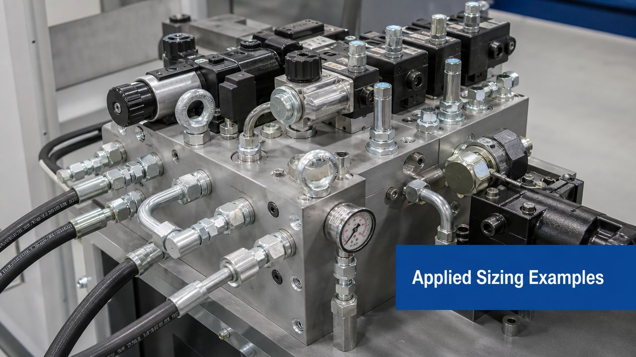
Worked Examples for Mobile and Industrial Use
Worked examples are where hydraulic accumulator sizing stops being abstract. The exact formula used will depend on the thermodynamic model you've chosen, but the workflow is always the same. Define the duty, identify the pressure band, establish the usable oil volume, then choose the nearest practical commercial size after allowing for service reality.
Mobile machine example
Take a mobile application where the accumulator supports a short, fast-demand function. A common case is a machine function that needs immediate oil delivery before the pump can react, or where a brief reserve is needed for a safety-related movement.
The process looks like this:
- Record the minimum pressure below which the function becomes unacceptable.
- Record the maximum charging pressure available in normal operation.
- Calculate the usable fluid volume the circuit must receive during the event.
- Class the event as rapid cycling, because the discharge is quick.
- Set pre-charge in the accepted band relative to minimum pressure.
- Select the next practical shell size after adding margin.
Problems often arise in many mobile circuits. The engineer calculates volume correctly, then installs the unit remotely on convenient pipework rather than close to the function. The machine then behaves as though the accumulator is undersized because line losses and delay eat away at the expected benefit.
A compact hydraulic source can also change what size and response you need from the accumulator. If your system uses a self-contained mobile pack, this overview of a mobile hydraulic power unit is useful context when you're considering packaging and response.
Industrial example
Now take an industrial press or power-pack application where the accumulator supplements flow during a demand peak. The event is often less about emergency reserve and more about smoothing a short mismatch between pump delivery and actuator requirement.
In that case, the approach is slightly different in emphasis:
| Step | Industrial focus |
|---|---|
| Define pressure limits | Use the actual working band, not just relief valve settings |
| Determine oil demand | Base it on actuator movement during the high-flow part of the cycle |
| Review cycle speed | Slow enough may justify an isothermal assumption |
| Check installation point | Keep pipe runs short to protect response |
| Add practical margin | Allow for long-term drift and service variation |
In industrial systems, the accumulator often looks perfect on paper and disappointing on the machine because the duty cycle was averaged instead of examined event by event.
The commercial selection then becomes a judgement call. You might have a theoretical requirement that sits between standard vessel sizes. In that case, choose the standard option that still protects the function once field variation, pre-charge tolerance and installation reality are considered.
I'm deliberately not inventing a neat catalogue price here. Real UK pricing depends heavily on vessel type, pressure rating, approvals, porting, and brand. If you need cost accuracy, get a live quotation against a full specification rather than relying on broad online price assumptions.
Choosing the Right Accumulator Type
Sizing the volume is only half the decision. The accumulator type determines how the unit responds, how it tolerates contamination, how easy it is to service, and where it makes sense to use it.
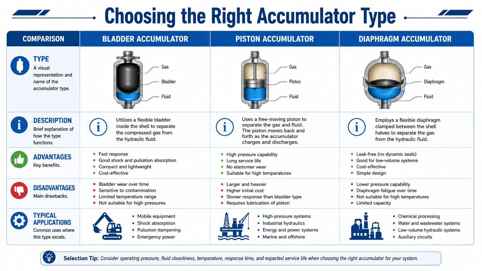
Bladder accumulators
Bladder units are often the first choice for general hydraulic work. They respond quickly, suit many common energy-storage and pulsation-damping duties, and are widely understood by service teams.
They're a strong option when you need fast reaction and a compact, familiar package. They are less forgiving if the fluid is dirty or if the application is badly controlled and repeatedly abuses the bladder.
Piston accumulators
Piston accumulators come into their own where gas and fluid separation needs to be very controlled, or where larger volumes and more demanding pressure duties are involved. They also appeal in applications where the designer wants a more configurable internal arrangement.
Their trade-off is that they are not always the first answer for the quickest transient response. They can also be less attractive where contamination control is poor and maintenance discipline is weak.
Diaphragm accumulators
Diaphragm types suit smaller systems and compact packages. They can be very effective in mobile or auxiliary duties where space is tight and the required volume is modest.
They aren't usually the answer when you need large stored volume. Their strength is compactness and responsiveness in the right range, not broad application coverage.
A practical comparison
| Type | Best at | Watch-outs | Typical fit |
|---|---|---|---|
| Bladder | Fast response, general-purpose hydraulic duties | Sensitive to abuse and contamination | Mobile plant, shock absorption, pulsation damping |
| Piston | Large volume, controlled gas-fluid separation | More dependence on internal condition and cleanliness | Industrial systems, higher-volume storage |
| Diaphragm | Compact size, quick response in small systems | Limited suitability for larger storage duties | Small mobile and auxiliary circuits |
If you're choosing between them, start with the job rather than the product family.
- For fast general-purpose support, bladder is often the practical answer.
- For larger-volume or higher-pressure industrial work, piston often deserves serious consideration.
- For tight packaging and smaller demand, diaphragm can make sense.
What doesn't work is selecting by habit. Plenty of poor accumulator systems are the result of specifying the same type every time, regardless of duty.
From Calculation to Procurement A UK Checklist
This is the point many articles skip. You can complete the hydraulic accumulator sizing exercise correctly and still buy the wrong unit. In the UK, that usually happens because the final specification is incomplete from a compliance, documentation or installation standpoint.
A major underserved issue in accumulator selection is UK-specific compliance and verification for pressure equipment. Public sizing guides often deal with pressure range, flow demand, pre-charge and temperature, but they rarely connect those calculations to the UK pressure-safety step. In practice, accumulator vessels and related assemblies can fall within the relevant pressure equipment framework, so engineers need to check not only capacity but also conformity assessment, documentation, and whether the item is being treated as a vessel or assembly under the applicable rules (Hydroll discussion of industrial accumulator sizing and compliance considerations).

The checklist that prevents bad purchases
Use this when preparing an enquiry or purchase specification:
- Compliance status. Confirm whether the accumulator and any related assembly meet the applicable UK pressure equipment requirements for the intended market and installation.
- Marking and documentation. Ask for the conformity documents, test information, and traceability package before placing the order.
- Pressure rating. Match the vessel and all associated components to the actual operating pressure band, not an assumed nominal figure.
- Port specification. Define thread form, size, adaptor needs, and whether the supplier is to provide the charging or isolation hardware.
- Seal compatibility. State the hydraulic fluid and environmental conditions clearly so the elastomer choice is not left to guesswork.
- Temperature exposure. Include expected ambient and operating range in the enquiry.
- Mounting arrangement. Tell the supplier whether the unit will be vertical, horizontal, bracketed, manifold-mounted, or remote.
- Maintenance access. Make sure the charging valve and service points can be reached once installed.
- Site acceptance requirements. Some plants want more than legal minimums. Include site standards up front.
Installation is part of specification
A common failure mode is poor placement. Technical guidance states that accumulators should be located near the valves or point of demand to minimise pressure losses and preserve response time. If you leave the installation location out of the procurement package, somebody else will decide it later based on convenience.
That's how you end up with a decent component in a bad position.
Site lesson: When an accumulator is mounted where the fitter had room rather than where the circuit needs it, the machine often behaves as though the calculation was wrong.
Pre-charge also belongs in the procurement and commissioning documents. If the target charge pressure isn't stated clearly, the installed unit may be left at a shipping condition or adjusted by rule of thumb. Neither is acceptable on a serious system.
What a procurement-ready specification should include
A usable UK specification usually contains:
| Specification item | Why it matters |
|---|---|
| Duty description | Tells the supplier what the accumulator is meant to do |
| Pressure band | Prevents selection against the wrong operating range |
| Required usable oil volume | Confirms the sizing basis |
| Thermodynamic assumption | Shows whether the duty is rapid or slow cycle |
| Pre-charge requirement | Prevents commissioning ambiguity |
| Accumulator type | Bladder, piston or diaphragm |
| Fluid and seal requirements | Protects compatibility and service life |
| Mounting and porting | Avoids installation rework |
| Compliance documents required | Supports procurement and site approval |
There's also a commercial side to this. Procurement teams trying to reduce total cost often focus on unit price first. That's understandable, but with pressure equipment it can be expensive if the cheaper item arrives without the right documentation or doesn't fit site standards. Broader purchasing discipline matters. These actionable procurement strategies for automation are useful because the same principle applies here: define the requirement properly, or cost reduction turns into rework.
If you work in UK MRO, this is usually where the best savings are found. Not by buying the cheapest accumulator, but by buying one that fits the machine, the duty, the paperwork requirement and the maintenance reality the first time.
Get Your Sizing Right Every Time
Good hydraulic accumulator sizing comes from discipline, not guesswork. Get the system data first. Match the calculation method to the duty cycle. Choose the accumulator type for the job, not by habit. Then finish the process properly with installation planning, pre-charge definition and UK compliance checks.
That last step is where many otherwise competent selections fall apart. A vessel that works in theory can still be wrong in procurement or awkward in service.
The safest approach is to treat sizing as part of the whole circuit decision. Pressure band, usable volume, cycle speed, accumulator type, mounting position and documentation all belong in the same conversation. When those pieces line up, accumulators do exactly what they should do. Quietly support the system and stay out of the trouble list.
For application advice, replacement support, or help turning a calculation into a procurement-ready specification, contact MA Hydraulics Ltd. Phone 01724 279508 today, or send us a message.
