A machine that looks strong on paper can still fail in service. You see it when a press won't reach force, when a stabiliser leg creeps instead of holding, or when a winch motor slows badly as the load comes on. In nearly every case, somebody relied on ideal figures and skipped the losses, geometry, or duty conditions that decide whether a system works outside a drawing office.
That's why mechanical advantage calculations matter. They're not just a schoolbook exercise for levers and pulleys. In hydraulic work, they're the link between the pressure you can generate, the area or displacement you've chosen, and the force or torque the machine can deliver where it counts.
Why Accurate Calculations Are Crucial
A common workshop problem is simple enough to describe. The cylinder is the size the machine builder specified. The pump is running. Pressure appears to be available. Yet the platen won't press the job consistently, or the attachment lifts cleanly at one angle and struggles at another. The mistake usually isn't dramatic. It's small assumptions stacked together.
One designer uses the cylinder's full bore area without checking the linkage angle. Another sizes a motor for theoretical torque and forgets pressure drop through the valve bank and hoses. A repair team swaps in a “near enough” replacement because the mounting fits, then wonders why the machine feels lazy under load. The numbers may look close. The output often isn't.
Where bad maths shows up first
Mechanical advantage calculations affect more than raw lifting force. They influence:
- Component sizing: An undersized cylinder or motor won't meet the load. An oversized one may create control problems, higher heat generation, and unnecessary strain elsewhere in the circuit.
- Cycle behaviour: A system that makes force at one part of the stroke may lose it at another because the mechanical advantage changed.
- Service life: If a machine operates near its limit all the time, seals, couplings, pumps, hoses, and structures pay the price.
- Fault finding: Without a calculation baseline, people chase symptoms instead of causes.
Practical rule: If the machine only “just works” when everything is cold and unloaded, the original calculation was probably too optimistic.
Accurate calculation also protects against the opposite error. Some systems are oversized to avoid risk, but that can create blunt, hard-to-control motion and wasted energy. In hydraulic machinery, excess force doesn't come free. It often means larger components, more oil movement, more heat, and more demand on the prime mover.
The real cost of getting it wrong
Poor calculations waste time twice. First during design or specification, then again when someone has to diagnose why the finished machine doesn't behave as expected. On the workshop floor, that usually means repeated pressure checks, valve changes, seal inspections, and unnecessary part swaps before anyone revisits first principles.
Good engineers don't guess from catalogue headlines. They work backwards from the load, the geometry, the required motion, and the operating conditions. That's where mechanical advantage calculations stop being theory and start becoming useful.
The Core Principles of Mechanical Advantage
Mechanical advantage is the relationship between what you put into a system and what you get out. In force terms, the basic expression is:
Mechanical Advantage = Output Force ÷ Input Force
If you apply a smaller input force and the mechanism delivers a larger output force, the system has mechanical advantage. That's true whether the mechanism is a lever, a pulley system, a gearbox, or a hydraulic actuator working through a linkage.
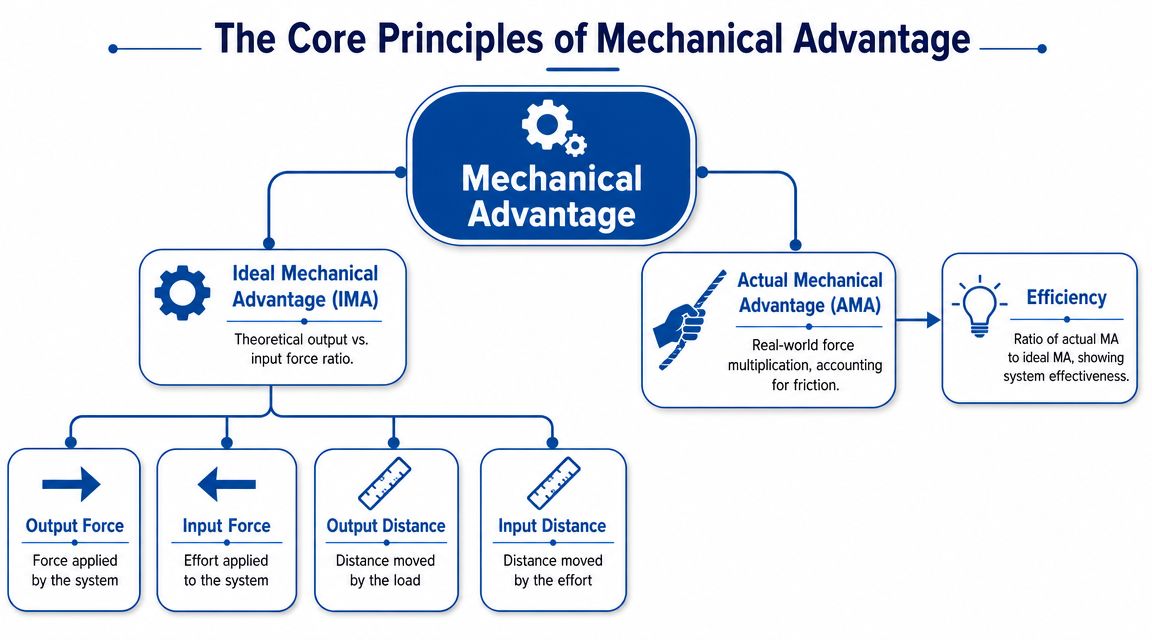
Ideal and actual aren't the same thing
Ideal Mechanical Advantage (IMA) is the theoretical ratio in a perfect system. No friction. No bending losses. No seal drag. No leakage. It's useful because it gives you a clean starting point.
Actual Mechanical Advantage (AMA) is what the machine really produces once losses are included. That's the value that matters in service.
A practical way to express the relationship is:
AMA = IMA × Efficiency
That last term is where most trouble starts. Efficiency is the bridge between neat theory and workshop reality. Ignore it, and your calculations will flatter the machine.
Force and distance always trade places
Mechanical advantage never gives you something for nothing. If a system multiplies force, you normally pay for it with extra travel, lower speed, or both.
A lever shows this clearly. If the effort arm is longer than the load arm, a modest input force can move a larger load. But the effort end must travel farther. The same idea applies to a pulley block, where you pull more rope length to move the load a shorter distance. In hydraulics, the equivalent trade-offs often appear as pressure versus area, or torque versus speed.
The quickest way to spot impossible figures is to ask what the machine is giving up in return. If the answer is “nothing”, the assumption is wrong.
Why geometry matters as much as arithmetic
Mechanical advantage calculations are rarely static in working machinery. A linkage can start with favourable mechanical advantage and finish in a weak position. A cylinder can produce its highest extension force in straight-line terms, yet the mechanism attached to it may waste much of that force at a poor angle.
Engineers often combine simple force calculations with motion geometry and gearbox ratios. A reduction gearbox is a good example. It increases output torque by reducing speed, but only within the limits of the losses and load path around it.
A compact way to think about it
Use this sequence when checking any system:
- Define the input: hand force, motor torque, hydraulic pressure, or prime mover power.
- Find the ideal ratio: lever arms, pulley strands, gear teeth, piston area, or motor displacement.
- Apply real losses: friction, leakage, drag, and pressure drop.
- Check the output at the load: not just at the actuator, but where the work is done.
That habit prevents a lot of expensive optimism.
Calculating Advantage in Common Mechanical Systems
Hydraulic engineers still need a solid grasp of ordinary mechanical systems. Cylinders and motors rarely work alone. They push levers, drive chains, turn gears, and tension wire ropes. If the external mechanism is wrong, a perfectly healthy hydraulic unit can still underperform.
Lever calculations in metric terms
For a simple lever, the ideal mechanical advantage is:
Mechanical Advantage = Effort Arm ÷ Load Arm
The effort arm is the distance from the pivot to where the input force is applied. The load arm is the distance from the pivot to where the load acts.
Take a straight lever with an effort applied 800 mm from the pivot, lifting a load positioned 200 mm from the pivot.
MA = 800 mm ÷ 200 mm = 4
That means the lever ideally multiplies the input force by four.
How the lever class changes the job
You don't need a different formula for first, second, and third class levers, but the layout changes what the system is good at.
- First class: Pivot between effort and load. Think of a pry bar.
- Second class: Load between pivot and effort. Useful where force multiplication matters most.
- Third class: Effort between pivot and load. Often chosen for speed and movement rather than force gain.
A hydraulic linkage often behaves like one of these even if it doesn't look like a textbook lever. The cylinder pin position, the main pivot, and the bucket or jaw load point define the actual ratio.
A cylinder can generate plenty of force and still lose the fight if it's pushing through a poor lever arm.
Worked lever example
Suppose a cylinder applies 10,000 N to a lever at 600 mm from the pivot. The load point sits 150 mm from the pivot.
MA = 600 ÷ 150 = 4
Output force = 10,000 N × 4 = 40,000 N in ideal terms.
In service, pin friction, bush wear, and changing angles reduce that figure. The arithmetic is still the right starting point because it tells you whether the layout is sensible before losses are added.
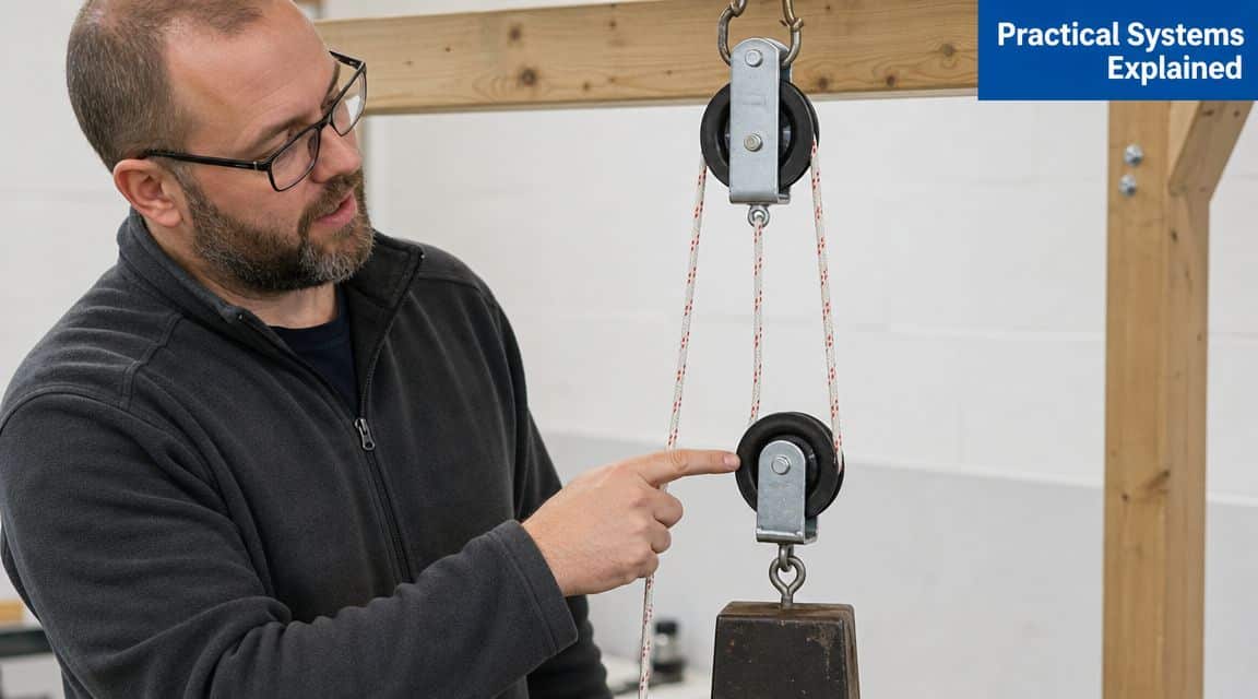
Pulley and block and tackle systems
For a simple pulley system, ideal mechanical advantage is usually based on the number of rope sections supporting the moving load.
If a moving block is supported by four rope sections, the IMA is 4. In theory, an input pull of 500 N could support or lift a 2,000 N load.
The trade-off appears immediately. To move the load 1 metre, you must pull 4 metres of rope.
What trips people up with pulleys
Pulley systems look generous in theory and disappointing in practice because friction arrives early. Every sheave, bearing, rope bend, and misalignment steals something. That's why counting strands alone is useful for layout, but not enough for final expectation.
Watch for these errors:
- Miscounting support lines: Count the rope sections carrying the moving block, not every visible rope segment in the rig.
- Ignoring direction changes: Extra pulleys used only to redirect the pull don't always increase load support.
- Assuming clean movement: Dirty sheaves, side loading, and stiff rope can make a “high advantage” rig feel poor very quickly.
Gear ratio calculations
For a basic gear pair, the ratio comes from the number of teeth:
Gear Ratio = Teeth on Driven Gear ÷ Teeth on Driving Gear
If the driving gear has 20 teeth and the driven gear has 60 teeth:
Gear Ratio = 60 ÷ 20 = 3
So the output turns at one-third of the input speed, while torque is multiplied ideally by three.
Compound reduction example
Now consider two stages:
- First pair: 15 tooth gear driving 45 tooth gear
- Second pair: 12 tooth gear on the same shaft driving 48 tooth gear
First stage ratio: 45 ÷ 15 = 3
Second stage ratio: 48 ÷ 12 = 4
Overall ratio: 3 × 4 = 12
That means the final shaft turns once for every twelve turns of the input shaft, ignoring losses.
Why these examples matter in hydraulic work
Many hydraulic systems only make sense once these mechanical ratios are included. A motor might drive a reduction train before it reaches a conveyor or winch. A cylinder may act on a bell crank before the force reaches the tool. If the external mechanism changes the ratio, your hydraulic calculation must follow the load path all the way through.
That's the discipline behind useful mechanical advantage calculations. Don't stop at the actuator. Finish at the job.
Mastering Hydraulic Mechanical Advantage Calculations
Hydraulic systems turn pressure and flow into force and motion. The arithmetic is straightforward. The discipline lies in using the right area, the right units, and the correct side of the piston.
Cylinder force from pressure and area
For a hydraulic cylinder:
Force = Pressure × Area
In metric hydraulic practice, pressure is often given in bar and dimensions in mm. You can calculate piston area from bore diameter:
Piston area = π × (bore diameter² ÷ 4)
For retraction force, you must use the annulus area, not the full piston area:
Annulus area = Piston area − Rod area
That difference matters. A cylinder almost always produces less force retracting than extending because the rod takes up area on the rod side.
Worked example for a cylinder
Take a cylinder with:
- Bore = 100 mm
- Rod = 50 mm
- Pressure = 210 bar
First calculate the full piston area.
Piston area = π × (100² ÷ 4)
Piston area = π × 2,500
Piston area ≈ 7,854 mm²
Now calculate rod area.
Rod area = π × (50² ÷ 4)
Rod area = π × 625
Rod area ≈ 1,963 mm²
So the annulus area is:
Annulus area ≈ 7,854 − 1,963 = 5,891 mm²
To convert pressure in bar and area in mm² into force in newtons, a practical expression is:
Force (N) = Pressure (bar) × Area (mm²) × 0.1
Extension force
Force = 210 × 7,854 × 0.1
Force ≈ 164,934 N
Retraction force
Force = 210 × 5,891 × 0.1
Force ≈ 123,711 N
If you need the result as mass equivalent for workshop discussion, divide the force in newtons by standard gravity to get an approximate tonne-force value. In design work, it's better to stay in newtons and treat tonnes as an informal reference only.
Don't mix up bore area with annulus area. That one mistake causes a lot of bad cylinder selections.
Hydraulic motor torque
Rotary output works differently. With a hydraulic motor, the usual theoretical torque expression is:
Torque (Nm) = (Pressure (bar) × Displacement (cc/rev)) ÷ 62.8
This gives a theoretical torque figure before real losses are considered.
Take a gear motor with:
- Pressure = 180 bar
- Displacement = 80 cc/rev
Torque = (180 × 80) ÷ 62.8
Torque ≈ 229.3 Nm
That tells you what the motor could ideally deliver at that pressure and displacement. It doesn't tell you what reaches the output shaft once internal leakage, mechanical friction, and pressure drop through the circuit are included.
Use the pressure that exists at the actuator
A common error in hydraulic mechanical advantage calculations is using the relief valve setting as though it's guaranteed pressure at the working component. It isn't. The actuator only sees what remains after losses through hoses, fittings, valves, manifolds, and any other restrictions in the path.
If you need a refresher on the underlying relationship, this guide on how pressure is calculated is a useful reference.
Key hydraulic calculation formulas
| Component | Parameter | Formula (Metric Units) |
|---|---|---|
| Hydraulic cylinder | Piston area | π × (bore diameter² ÷ 4) |
| Hydraulic cylinder | Rod area | π × (rod diameter² ÷ 4) |
| Hydraulic cylinder | Annulus area | Piston area − Rod area |
| Hydraulic cylinder | Force | Pressure (bar) × Area (mm²) × 0.1 |
| Hydraulic motor | Theoretical torque | (Pressure (bar) × Displacement (cc/rev)) ÷ 62.8 |
Where calculations go wrong in practice
Most mistakes come from one of four places:
- Unit confusion: Mixing mm, cm, m, bar, MPa, and litres without checking conversions.
- Using nominal instead of actual conditions: Catalogue pressure, rather than measured pressure at the component.
- Ignoring retract side force: Especially on clamp circuits and return strokes under load.
- Stopping at the actuator: Force at the cylinder isn't the same as force at the tool once the linkage geometry changes it.
A better way to check a design
For any cylinder or motor application, run the maths in this order:
- Define the required load at the point of work.
- Translate that through any lever, gear, or pulley ratio.
- Calculate the actuator force or torque needed.
- Check whether the available system pressure supports it.
- Only then choose bore, rod, displacement, and speed requirements.
That order keeps the hydraulic part tied to the actual machine instead of treated in isolation.
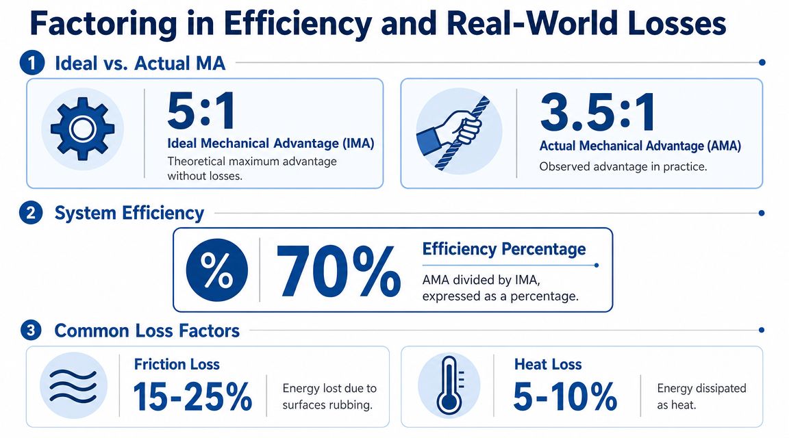
Factoring in Efficiency and Real-World Losses
Ideal results are useful, but they're never the final answer. Real hydraulic systems lose output through seal friction, internal leakage, pressure drop, oil heating, and mechanical drag elsewhere in the drivetrain. The effect is cumulative, not isolated.
A useful benchmark comes from Fluid Power World's discussion of hydraulic efficiency, which notes that in a typical mobile or industrial hydraulic system, only 75-85% of the input power from the prime mover is converted into useful work at the actuator, with the rest lost primarily as heat. That's the broader system picture engineers need to keep in mind when a design looks fine on paper but feels weak in service.
Where the losses come from
In day-to-day hydraulic work, the usual loss points are easy to recognise:
- Cylinder sealing friction: New cylinders may feel strong unloaded but still need breakaway force before useful work begins.
- Motor internal leakage: As wear increases, more oil slips past internal surfaces instead of producing torque.
- Pressure drop in the circuit: Long hose runs, restrictive valves, elbows, and undersized fittings all reduce pressure at the actuator.
- Mechanical losses after the actuator: Chains, bearings, gear meshes, and pivots all consume part of the output.
That's why volumetric efficiency matters when diagnosing motors and pumps. A machine can show acceptable pressure at one test point and still underperform because the flow and displacement relationship inside the component has deteriorated.
If the actuator calculations look right but the machine still lacks force or torque, check what pressure and flow actually arrive under load. That usually reveals whether the loss is in the circuit or inside the component.
Revisiting the cylinder example with efficiency
The cylinder example above gave an ideal extension force of 164,934 N for a 100 mm bore cylinder at 210 bar.
If the available output at the cylinder is reduced by system losses, the practical force at the work point will be lower. Without inventing a fixed component efficiency figure, the safe workshop approach is to treat the ideal figure as the ceiling, then work down after measuring pressure at the component and checking the mechanism attached to it.
That's the important distinction. The ideal force calculation tells you what the cylinder could produce from pressure and area. It does not guarantee that the machine structure, linkage, and hydraulic path deliver that amount where the work happens.
What works and what doesn't
What works is conservative sizing based on measured conditions, realistic load cases, and a clear understanding of where the force goes after it leaves the actuator.
What doesn't work is selecting a cylinder or motor from catalogue values alone, then assuming full rated output survives the trip through valves, hoses, pivots, and gear sets. That approach nearly always leads to heat, sluggishness, and endless adjustment.
Applying Calculations to Select and Troubleshoot Components
Once the calculations are done properly, component selection gets far easier. You're no longer choosing a cylinder because the bore “looks about right” or a motor because it matches the mounting. You're matching required force or torque at the job to the actual output the system can support under working conditions.
For selection, start with the load at the tool or mechanism. Then account for linkage, gearing, or rope ratio before choosing the hydraulic component. A gearbox, clevis mount, or pin arrangement can change the effective result as much as the hydraulic unit itself. Tolerance stack-up matters here as well, especially in fabricated mechanisms, and this practical guide to GD&T is worth reading if alignment and fit are affecting motion quality.
For troubleshooting, the same maths becomes a filter. If the calculated cylinder force should be adequate but measured pressure is low, the fault may sit with the pump, relief valve, or pressure losses in the line. If pressure is present but output remains poor, look harder at internal leakage, worn seals, mechanical binding, or a linkage geometry problem that robs force at the point of work.
The strongest habit is simple. Calculate first, measure second, replace parts third. That order saves money and usually finds the fault faster.
If you need help matching cylinders, motors, gearboxes, valves, or complete power pack components to a real working load, MA Hydraulics Ltd can help. Phone 01724 279508 today, or send us a message for friendly, knowledgeable support.
