A lot of load bearing problems don't start with a dramatic collapse. They start with a base plate that no longer sits flat, a power pack frame that picks up vibration it never had before, a bracket hole that goes oval, or a cylinder mount that begins to fret around the pin. The machine still runs, so the issue gets ignored. Then downtime arrives at the worst possible moment.
In hydraulic work, that's the trap. People ask whether a frame, bracket, plinth or floor can “take the load” as if capacity is one number. In practice, the useful question is narrower and much more important. Can it carry the load, under real operating conditions, without bending, settling, cracking, vibrating, or shifting out of alignment?
That distinction matters on mobile plant, industrial skids, machine bases, and power pack installations across the UK. It matters just as much for steelwork and mountings as it does for the concrete and ground underneath them. A component can survive in the strict sense and still fail in service.
The True Cost of Miscalculating Load Capacity
A common failure sequence in hydraulics is painfully ordinary. A power pack goes onto a base frame that looked heavy enough in the workshop. It's lifted into place, piped, wired, commissioned, and signed off. Under steady load, everything appears fine. Then the machine sees repeated starts, pressure spikes, and vibration. The frame twists slightly, the anti-vibration mounts stop sharing load evenly, one corner begins to settle, and pipework starts carrying movement it was never meant to absorb.
Nobody describes that as a load bearing capacity problem at first. They call it a noise issue, a cracked weld, a leaking fitting, or nuisance downtime. But the root cause is often the same. The load path was misunderstood.
On mobile equipment, the pattern is similar. A bracket is sized to hold static weight, but the actual service case includes shock loading, torsion from uneven ground, and side load introduced by hose routing or cylinder geometry. The part doesn't snap on day one. It deforms, loosens fasteners, and starts a chain of secondary failures.
A bracket that “hasn't broken” may already be unfit for service if it has moved enough to misalign a coupling, strain pipework, or change cylinder loading.
The expensive part is rarely the steel alone. It's the lost production time, emergency call-out, fluid loss, contamination risk, and the knock-on damage to pumps, couplings, valves, and mountings. In hydraulic systems, poor support conditions rarely stay local. They travel.
That's why load bearing capacity has to be treated as a system issue. The frame matters. The fixings matter. The concrete matters. The soil under the slab or footing matters. And in many installations, the first unacceptable condition isn't collapse. It's movement.
Defining Load Bearing Capacity in Practice
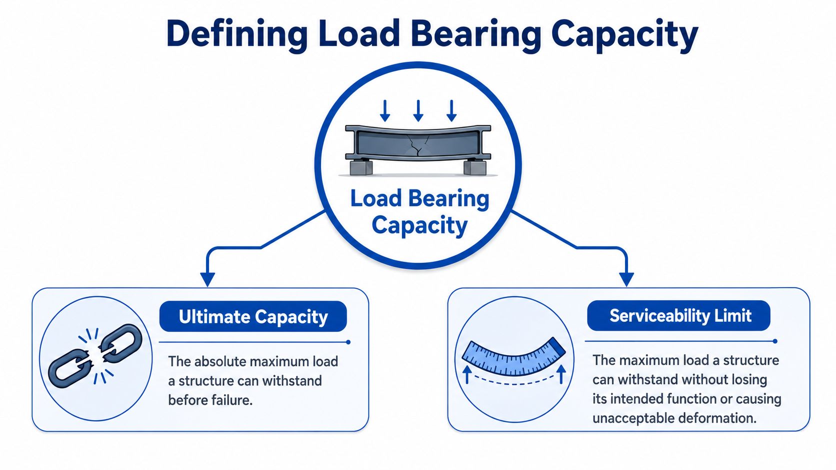
Load bearing capacity has two meanings in practical engineering, and confusing them causes trouble.
The first is ultimate capacity. That's the point at which a part, support, or ground condition reaches failure. It might crack, buckle, shear, punch through, or collapse. Ultimate capacity answers the blunt question: what load causes structural failure?
The second is serviceability limit. That's the point at which the item still exists, but no longer performs its job properly. It may sag, vibrate, settle, tilt, loosen, or distort enough to create operational problems. In hydraulic equipment, this is often the limit that matters.
The shelf example engineers still use
A shelf gives a simple way to separate the two. If you keep adding weight until the shelf snaps, you've found ultimate capacity. If it sags so badly that books slide, doors won't shut, or fixings start pulling loose, you've already exceeded serviceability.
Hydraulic assemblies behave the same way. A motor bracket may stay intact but bend enough to throw coupling alignment out. A skid may remain standing but deflect enough to stress rigid pipe runs. A machine base may never come close to collapse, yet settle enough to create vibration and repeated seal or hose issues.
Why serviceability usually governs in hydraulic installations
Hydraulic systems are sensitive to geometry. Small movement in a support can create a large practical problem because it changes how force travels through the assembly. A little twist in a frame can alter shaft alignment. A little settlement under one side of a plinth can shift pipe stress. A little bracket flex can add side load into a cylinder pin or rod.
That's why experienced engineers don't stop at “will it break?”. They also ask:
- Will it stay aligned under operating load?
- Will it deflect enough to affect couplings, seals, or hoses?
- Will it vibrate when the motor starts or the valve shifts?
- Will the support settle enough to introduce tilt or uneven bearing?
Practical rule: If movement changes function, then movement is failure, even if nothing has fractured.
For hydraulic power packs, actuator supports, machine plinths, and mobile mounting frames, serviceability is often the first boundary crossed. Ultimate collapse sits further away. That makes a “safe” looking installation deceptive if nobody has checked deformation, restraint, and support stiffness.
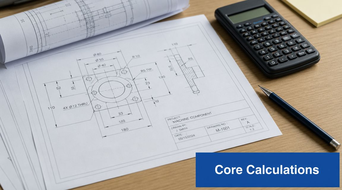
Essential Formulas and Calculation Examples
The starting point for most load checks is still the simplest one:
Stress, σ = Force, F / Area, A
That relationship doesn't solve every problem on its own, but it tells you where to begin. If the force rises or the effective area drops, stress increases. If stress becomes too high for the material or connection, something yields, cracks, or crushes.
What stress are you actually checking
A hydraulic assembly rarely sees only one stress type.
- Tensile stress pulls a part apart. Cylinder rods, tie rods, bolts, and lifting lugs often see this.
- Compressive stress squeezes a part. Mounting feet, support blocks, and frame members under bearing load see compression.
- Shear stress tries to slide one part past another. Pins, keyways, bolts, and weld throats often fail in shear.
In real equipment, these can combine with bending. That's where quick hand calculations can become misleading if the load path isn't clear. A bracket that looks adequate in direct compression can still fail because the force acts off-centre and introduces bending.
If you're checking fluid force before you check the steelwork, it helps to understand how hydraulic pressure is calculated because pressure, piston area, and resulting force are the bridge between the fluid side and the mechanical side.
Worked example for a cylinder rod in tension
Take a simplified case. A cylinder rod carries an axial tensile force. The rod diameter is known, so you calculate cross-sectional area, then divide force by area to estimate tensile stress.
The method is straightforward:
- Find the force from the hydraulic load case.
- Calculate rod area from the rod diameter.
- Divide force by area to get stress.
- Compare the result with the allowable stress for the selected rod material and design basis.
- Check the governing failure mode. Tension may not be the governing issue if the rod also sees buckling, side load, or thread root concentration.
That last point matters. A cylinder rod can look acceptable in pure tension but still fail because the clevis geometry introduces bending or because the extended stroke creates a buckling problem in compression. The arithmetic is easy. The loading assumption is where most mistakes happen.
For civil and support work, the same principle applies when people are determining correct retaining wall size. The formulae are only useful if the actual restraints, soil action, surcharge, and bearing conditions have been identified correctly.
Worked example for a bracket in compression
Now consider a simple steel mounting bracket carrying compressive load through a base area. You'd again use stress equals force over area, but the useful engineering check doesn't stop there.
Ask three questions in order:
- Is the bearing stress acceptable at the contact surface?
- Is the bracket stocky enough to resist local buckling?
- Is the load concentric, or does eccentricity create bending in the leg or base plate?
A bracket can have low average compressive stress and still distort because one edge takes most of the load. That usually happens when the mating surface isn't flat, grout is poor, bolt tightening is uneven, or fabrication tolerance leaves a gap. In that case, one corner carries the load first and the effective area is much smaller than the drawing suggests.
The same warning applies to concrete pads and machine bases. The nominal footprint may look generous, but if the frame is twisted or the base isn't fully supported, the actual bearing area reduces sharply.
A short visual explainer can help if you need a refresher on the mechanics behind these checks:
What hand calculations do well
Hand checks are useful for screening. They catch obvious under-sizing, poor bearing area, and unrealistic assumptions. They also force you to define the load path clearly.
What they don't do well is capture complex frame behaviour, local stress concentrations, weld detail effects, or dynamic interaction across a full hydraulic skid. If the component is safety-critical, highly loaded, repeatedly cycled, or sensitive to alignment, hand calculations should be the start of the review, not the end.
Key Factors Influencing Load Capacity
A rated capacity only means something if the actual installation matches the conditions behind that rating. In hydraulic equipment, it often doesn't.
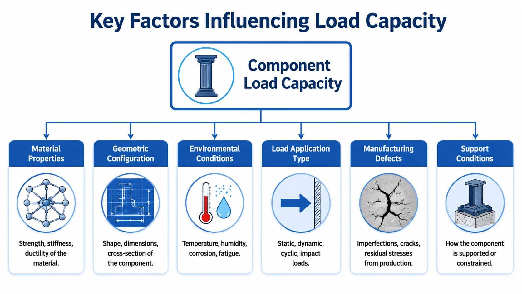
Material and stiffness both matter
Strength gets most of the attention, but stiffness often decides whether the assembly performs properly. A member may be strong enough to avoid yielding and still be too flexible for accurate support.
That matters on motor brackets, valve manifolds on unsupported pipework, and power pack frames carrying pump and motor mass. If the structure flexes, alignment drifts and vibration rises. Once that starts, fatigue becomes a maintenance problem rather than a design check.
Geometry decides more than thickness
A thicker plate doesn't automatically solve a poor load path. Section shape, unsupported span, hole position, edge distance, and gusset layout all influence how the part carries force.
Two brackets made from the same material can behave very differently if one has a short, direct load path and the other carries the load through a long flexible leg. In workshop repairs, this is why “just weld on a bit more plate” often disappoints. Extra metal in the wrong place adds weight without fixing the weak geometry.
Loads want a clean path into the support. Every offset, gap, or flexible leg increases the chance of bending that wasn't in the original assumption.
Connections are often the first weak point
The part itself may be adequate while the joint is not. Weld toe cracking, bolt hole elongation, pin wear, and local crushing around fasteners are common signs that connection design was optimistic.
Look closely at these details:
- Weld transitions where stiffeners stop abruptly
- Bolt groups carrying eccentric load rather than pure clamp force
- Pinned joints that have developed clearance and impact loading
- Base plates bridging over uneven support instead of bearing fully
This is also where drivetrain components influence structural loading. If a gearbox changes torque delivery or introduces different mounting reactions, the support frame has to suit that reality. A basic overview of what a reduction gearbox does is useful when you're tracing those load paths across a hydraulic power unit or driven assembly.
Dynamic loading changes everything
Static weight is the easy part. Mobile hydraulics, cyclic actuation, pressure pulsation, abrupt valve shifts, and machine travel over rough ground create dynamic effects that make a calm-looking load case much harsher in service.
Field note: If the machine bangs, reverses, oscillates, or travels off-road, don't design only for static mass. The support will see more than dead load.
That's why cylinder mounts, stop brackets, and frame tabs fail even when the nominal force looked modest on paper. Repetition matters. Shock matters. Load reversal matters.
The support beneath the machine can govern the design
This is the part many hydraulic installations miss. The frame can be sound, the bolts can be correct, and the skid can still perform badly because the support under it moves.
UK geotechnical guidance is clear that presumed bearing values are only suitable for preliminary sizing and don't include settlement, which is often the serviceability limit that controls pads, bases, and foundations. The UWE guidance also shows how widely presumed values vary by soil class, from less than 100 kN/m² for loose sand to more than 600 kN/m² for dense gravel in its bearing capacity discussion, which is exactly why “what load can the ground take?” is too crude a question on its own (UWE geotechnical foundation bearing guidance).
For hydraulic power packs and machinery bases, that means the practical check isn't just whether the ground avoids shear failure. It's whether the support stays level enough, stiff enough, and stable enough for the equipment to keep working without unacceptable settlement, tilt, or vibration.
Environment and manufacture still count
Corrosion, moisture ingress, heat, poor weld quality, and residual distortion from fabrication all reduce real-world margin. So does poor installation.
A frame that was flat in fabrication can become twisted after lifting, grouting, and tightening if the support points aren't coplanar. Once that preload is locked in, the machine starts life already stressed.
Applying Safety Factors and Following Standards
A sound design doesn't run right up to the edge of calculated failure. It leaves margin because actual conditions are messy. Materials vary, welds aren't perfect, operating loads aren't always gentle, and support conditions on site rarely match the ideal drawing.
That margin is the factor of safety. Without it, a design may survive the textbook load case and still fail in service because the actual machine sees shock, misalignment, wear, or installation error. In hydraulic systems, those “small” deviations are routine, not exceptional.
Why the margin has to be deliberate
Designers sometimes treat safety factor as a vague comfort blanket. It isn't. It's a structured way to account for uncertainty and the consequence of getting the assumption wrong.
In UK foundation design, bearing capacity refers to the soil pressure that would trigger shear failure, while the allowable design pressure is set lower than ultimate capacity by a factor of safety. Independent geotechnical guidance also notes that footing width, embedment depth, groundwater, and soil shear strength all control the result, and in stratified soils the weaker layer can govern if its strength is less than one-third of the overlying average (independent bearing capacity guidance).
That principle translates directly to hydraulic installations. The support isn't judged only by the load at collapse. It's judged by the lower, usable load that allows for uncertainty and protects service life.
Standards matter because assumptions matter
Standards don't remove engineering judgement, but they do force discipline. They define design approaches, testing expectations, material assumptions, and manufacturing quality that stop people from relying on guesswork.
For anyone dealing with wider building compliance around installed equipment, Awesim Building Consultants provides a useful overview of code context that helps when hydraulic plant interfaces with structural and building requirements.
The danger in skipping standards isn't paperwork. It's that undocumented assumptions creep into the job, and nobody notices until the component is already in service.
Testing closes the loop
Even good calculations need validation. Material certification, weld inspection, pressure testing, fit-up checks, and alignment checks all confirm that the built assembly matches the design intent.
That matters most where failure is expensive but not immediately obvious. A frame can pass a visual inspection and still carry locked-in stress from poor fabrication. A mounting arrangement can look sturdy and still transfer load unevenly because the base isn't fully bearing. Safety factor helps. Verification proves whether the margin is still there after manufacture and installation.
Practical Advice for Selecting and Maintaining Components
The best load bearing decisions are usually made before the machine is built, and the second-best are made during routine inspection before damage spreads. Design teams and MRO teams need different habits, but both need to focus on the same point. Follow the load path, not just the part number.
For design engineers and OEMs
When selecting hydraulic components and their supports, don't rely on catalogue capacity alone. Check how the part is mounted, restrained, and loaded in the actual machine.
Use this as a working checklist:
- Start with the worst operating case: Include pressure spikes, start-stop duty, uneven terrain, jam conditions, and any off-centre loading.
- Check the mounting arrangement: A strong pump, motor, cylinder, or valve assembly still fails if the bracket or frame is too flexible.
- Ask where the reaction force goes: If that answer isn't clear on the drawing, the load path probably isn't mature enough.
- Review the support below the equipment: Published UK-relevant benchmarks for safe bearing capacity vary sharply by soil type, from below 75 kPa for soft clay, 75 to 100 kPa for firm clay, below 200 kPa for loose gravel, and 200 to 600 kPa for dense gravel, which is why site investigation changes footing size and excavation decisions for machinery bases (safe bearing capacity by soil type).
- Specify complete assemblies, not isolated parts: If you're procuring a hydraulic power unit, define frame stiffness, mounting points, footprint, lifting points, and operating duty. MA Hydraulics Ltd can supply bespoke power packs and component assemblies for mobile and industrial applications, but those assemblies still need correct support and installation details from the system designer.
- Match actuator selection to real side loading: If the application includes misalignment or external guidance issues, review whether a standard double acting hydraulic cylinder is being asked to do structural work it shouldn't do.
For MRO and service teams
Inspection should focus on change. A bracket that was straight and is now slightly bowed has already told you something useful. The same applies to witness marks, fretting, paint cracking around welds, and bolts that need repeated retightening.
Don't wait for a visible fracture. Repeated movement leaves clues long before the metal separates.
Here's a practical inspection table for site use.
| Inspection Point | What to Look For | Action if Found |
|---|---|---|
| Base plates and feet | Gaps under corners, grout breakdown, rocking, uneven contact | Re-level, re-support, and investigate whether the foundation or frame has moved |
| Welded brackets | Hairline cracks, rust bleed, paint splitting at weld toes | Stop crack growth, assess load path, repair only after root cause review |
| Bolt holes and fasteners | Oval holes, loose bolts, washer imprinting, joint slip marks | Replace damaged hardware, restore clamping, check for eccentric loading |
| Cylinder mounts and pins | Wear, fretting, misalignment, pin creep, bush damage | Measure clearances, replace worn parts, correct side load source |
| Frames and skids | Twist, local buckling, bowed members, fresh vibration marks | Check alignment, loading, and support flatness before returning to service |
| Pipework near supports | Cracked clamps, stressed fittings, movement witness marks | Re-route or re-support, then correct the structural movement causing the stress |
| Concrete plinths and floors | Cracking, edge crushing, settlement, local spalling | Assess bearing condition and whether load is spreading as intended |
| Corroded areas | Section loss, pitting around fasteners or welded details | Clean, assess remaining thickness, repair or replace before capacity reduces further |
What usually works and what usually doesn't
What works is simple, direct support. Full bearing surfaces. Short load paths. Proper gusseting. Clear restraint. Flat mounting faces. Good alignment.
What doesn't work is trying to cure recurring stress with thicker bolts, extra weld on top of a bad detail, or repeated seal replacement when the underlying issue is movement in the support structure. If a hydraulic component keeps failing in the same location, the component may not be underspecified. The surrounding structure may be lying to it.
Ensure Your System is Built to Last
Load bearing capacity isn't just about whether something collapses. In hydraulic systems, the earlier and more common failure is loss of function through movement, distortion, settlement, and vibration. The reliable installation is the one that keeps its geometry under real duty, not just the one that survives a basic load check.
That's also why hydraulic design often overlaps with wider structural and base construction decisions. On projects involving equipment pads or external support works, broader references such as commercial foundation concrete services can help frame the concrete side of the discussion, but the final judgement still has to come back to the actual machine loads, support conditions, and service limits.
If you need help selecting components, reviewing a mounting arrangement, or specifying a hydraulic power pack with the right structural support assumptions, contact MA Hydraulics Ltd. Phone 01724 279508 today, or send us a message to discuss your application.
