
You're usually looking for a hydraulic power pack because something standard has already failed on paper. The footprint is wrong. The duty is harsher than the catalogue unit was built for. The controls don't suit the machine. Or the pack will physically fit, but it won't give you the pressure, flow, protection, or compliance the job needs.
That's where a bespoke build earns its keep. A proper pack isn't just a motor bolted to a pump and tank. It's a matched assembly built around load, speed, duty, environment, electrical supply, and control method. If you get those decisions right early, the pack runs cooler, lasts longer, and is far easier to service. If you get them wrong, you spend your time chasing heat, noise, leaks, erratic movement, and nuisance failures.
From Concept to Custom Hydraulic Power
A lot of engineers start with the same question. They don't ask for a power pack. They ask for movement. Lift this platform. Clamp that tool. Power this cylinder. Hold this load safely. Run this function on a trailer, press, conveyor, tailboard, or mobile attachment.
That's the right way to think about how to make hydraulic power pack assemblies that work in service. The job comes first. The hardware follows.
The wider market points in the same direction. The global hydraulic power unit market was valued at USD 14.0 billion in 2025, with a projected 4.9% CAGR through 2036, and in the UK the strongest demand sits in mid-range packs from 7.5 kW to 75 kW, holding 48.2% market share for manufacturing and offshore applications, according to Fortune Business Insights on the hydraulic power unit market. That matters because most real-world builds aren't extreme one-offs. They sit in the middle ground where space, reliability, serviceability, and control all have to balance.
A bespoke unit makes sense when one or more of these apply:
- The machine has limited space and you need a compact reservoir, manifold, and motor layout.
- The duty cycle is specific so a generic pack would run too hot or waste power.
- The controls are non-standard such as proportional valve control, load-holding, or multi-function sequencing.
- The environment is harsh and the pack needs IP-rated protection, filtration, and sensible hose routing.
- The electrical supply changes the design because an industrial unit on 380V AC isn't built the same way as a mobile unit on 12V or 24V DC.
If you need a refresher on the basic principles behind force, flow, and pressure, how hydraulics work in practice is the first thing to get clear before choosing components.
A good hydraulic pack starts as an application brief, not a shopping list.
Defining Your Hydraulic Requirements
A power pack for a workshop press in Birmingham is not sized the same way as one for a tipping trailer in Yorkshire or a compact manifold block on offshore support equipment out of Aberdeen. The job decides the pack. Get the duty wrong at this stage and the rest of the build becomes expensive rework.
Start with the actuator and the load, not the motor catalogue. In practice, I ask a client what the machine must physically do, how often it does it, and what happens if it slows down under load. That usually exposes the actual design point far faster than starting with pump sizes.
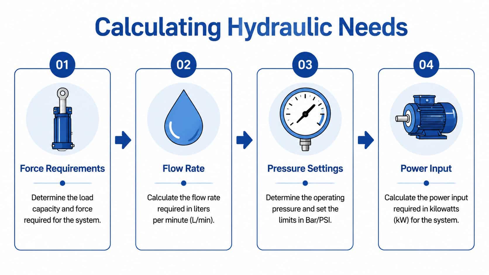
Start with force and pressure
Pressure comes from the force requirement and the working area of the cylinder or motor. If the machine must lift, clamp, press, or hold, convert that job into a load figure first.
Pressure (bar) = Force (N) / Piston Area (cm²)
If a cylinder must generate 10,000 N and the piston area is 50 cm², the working pressure is 200 bar. That is a sensible industrial number. It also gives you a starting point for pipework class, valve selection, filtration rating, and the safety margin you need for shock loads.
In UK industrial and mobile work, many systems land somewhere around 100 to 250 bar, but the right figure depends on the actuator geometry and the load case. A tail lift, a baler, and a small factory fixture may all sit in a similar pressure band while needing very different flow, control, and duty allowances. Pressure on its own tells you very little unless it is tied to the actual machine function.
Then calculate flow from speed
Flow sets actuator speed. If pressure answers "can it do the work?", flow answers "will it do it quickly enough?"
A practical starting formula is:
Flow rate (L/min) = (Cylinder volume × strokes/min × 60) / 1000
Take a 50 mm bore cylinder with a 200 mm stroke running at 30 strokes per minute. That points you to a flow requirement around 10 L/min. On paper, that looks straightforward. On the machine, you still need to account for real conditions such as hose expansion, valve losses, leakage, and whether that cycle rate is sustained for a full shift or only in short bursts.
This is one of the common mistakes on site. A pack can meet the calculated pressure and still feel slow because the designer used ideal figures and ignored the duty pattern.
Convert pressure and flow into motor power
Once pressure and flow are fixed, motor power is easy to estimate:
Power (kW) = (Flow rate × Pressure) / (600 × Efficiency)
At 10 L/min and 250 bar, the base requirement is 4.17 kW before losses. Allow for pump and motor efficiency and that often pushes a real industrial selection toward 5.5 kW, especially where the unit is expected to run repeatedly without getting hot.
There is a trade-off here. A smaller motor saves money and space, but it gives you less tolerance for voltage drop, heat build-up, worn pumps, and future changes to the machine cycle. A larger motor gives breathing room, but it increases running cost and can force a bigger tank, larger starter gear, and a larger enclosure. On UK factory installations where energy cost is under scrutiny, oversizing by habit is poor engineering.
Define the operating conditions properly
Duty cycle matters as much as force and speed. Intermittent clamp release on a production jig is one thing. Continuous running on a test rig or repeated motion on mobile plant is another. Heat generation, oil volume, cooler size, and motor rating all change with that duty.
Power supply also changes the design in a very practical way. A three-phase 400V AC unit for a fixed machine can use a very different motor and control arrangement from a 12V or 24V DC pack on recovery equipment, agricultural trailers, or access platforms. Space constraints, battery draw, start-up current, and cable size all become design limits on mobile equipment.
The environment comes next. Indoor manufacturing, food production washdown areas, quarries, marine exposure, and road-going equipment each drive different choices on filtration, reservoir breathers, paint finish, connector protection, and enclosure rating. This is also the point where UK compliance starts to matter. If the pack falls within PUWER expectations for workplace equipment, or PED considerations for pressurised assemblies, those decisions should influence the design brief before parts are ordered, not after assembly.
For a more detailed method, MA Hydraulics covers the design process in its guide to hydraulic power pack design for UK industrial and mobile applications.
Questions to settle before you buy anything
A usable design brief should answer these points clearly:
- Load requirement. What force is needed at the actuator in real service, not just in theory?
- Target speed. How fast must the cylinder or motor move to keep the machine productive?
- Duty pattern. Short intermittent use, frequent cycling, or long continuous runs?
- Power supply. Three-phase AC, single-phase AC, 12V DC, or 24V DC?
- Environment. Clean indoor use, outdoor exposure, corrosive conditions, or mobile equipment subject to vibration and shock?
- Control requirement. Simple on-off motion, load holding, pressure sequencing, or proportional control?
- Compliance considerations. Does the pack need to be built with PUWER, PED, CE or UKCA responsibilities in mind?
If you can answer those points clearly, the rest of the design becomes much more predictable.
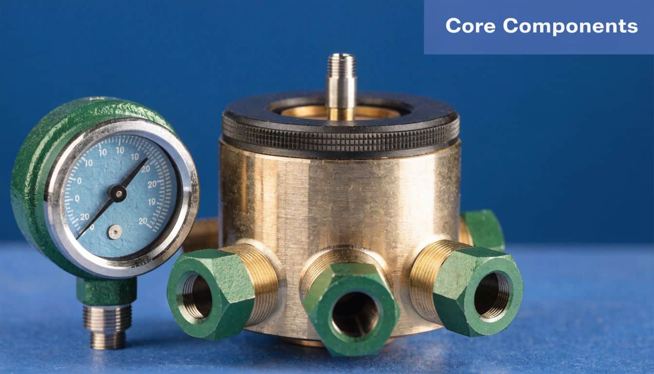
Selecting and Sizing Core Components
A power pack usually fails on paper before it fails in service. Poor component matching shows up later as heat, noise, slow cycle times, nuisance relief cracking, or a motor that trips every Monday morning when the oil is cold. Once pressure and flow are known, the job is to choose parts that suit the actual duty, the power supply, and the environment the pack will work in.
Motor and pump selection
Start with the pump, then match the motor properly. In a lot of UK workshop equipment, compact industrial machinery, and mobile attachments, a gear pump is still the sensible choice because it is simple, economical, and easy to replace. Groups 0 to 3 are common territory for bespoke packs using ranges such as Vivoil or OMT.
For a typical industrial pack, a 5.5 kW motor often sits in the right range for about 10 L/min at 250 bar with realistic pump efficiency, based on Hydrastore's hydraulic power pack sizing guidance. Treat that as a reference point, not a default setting. A press, a tail lift, and a factory fixture may all need 250 bar on paper, but their duty pattern can be completely different.
The trade-off is between installed headroom and running cost.
- Smaller motor and pump suit intermittent duty, lower starting current, and tighter spaces, but they leave little margin if the machine is later asked to run faster or more often.
- Larger motor and pump give breathing room and can improve cycle time, but they draw more power, generate more heat at idle losses, and usually push the tank size up as well.
On mobile packs, the trade-off changes again. A 12V or 24V DC unit may be the only practical option, but current draw becomes a design limit very quickly. On those builds, shaving unnecessary flow or pressure demand is often more useful than fitting a bigger motor.
If the application has fluctuating demand, spend time on efficiency before ordering parts. Fixed-displacement gear pumps are dependable, but they do not forgive poor matching. Packs built for modern UK industrial use are increasingly expected to avoid excess heat and wasted power, particularly where the unit will sit energised for long periods. The layout and matching choices in hydraulic power pack design for UK industrial and mobile applications are worth reviewing before the final motor and pump are locked in.
Reservoir, filtration, and temperature control
Tank size is one of the first places inexperienced builders try to save money. It is also one of the first places that causes trouble.
A practical starting point is a reservoir around 2.5 times the pump flow per minute, then adjust for duty cycle, ambient temperature, and available cooling surface. If the pack will run a clamp for a few seconds every hour, that rule may be generous. If it will power a conveyor function, a lifting table, or a continuously cycling production rig, it may be too small.
A small reservoir does three unhelpful things at once. It keeps oil hotter, gives entrained air less time to separate, and concentrates contamination. The result is usually foaming, unstable motion, shortened seal life, and oil that ages too quickly.
Build the tank to support the circuit:
- Use baffles to separate return flow from the suction area.
- Keep the pump inlet flooded and unrestricted so the pump is not fighting for oil.
- Specify filtration for the valve and actuator tolerances, not just what happens to be on the shelf.
- Leave access around filters, breathers, and level gauges so routine service can be done on site.
Temperature control needs the same discipline. Do not assume the steel tank will shed enough heat just because the pack looks lightly loaded. If the relief valve will crack regularly, or flow will be throttled for speed control, heat generation should be treated as part of the design, not as a commissioning surprise.
Valves, manifolds, and control strategy
Valve selection should follow machine function, not catalogue habit. A single-acting lift with hose burst protection needs a very different arrangement from a double-acting clamp circuit or a multi-station pack feeding several actuators.
CETOP directional valves are widely used in UK industrial packs because they make service, replacement, and later modifications easier. For a custom build, that matters. A compact manifold block with no spare ports may look tidy on the bench, but it becomes awkward the first time someone needs to add a gauge point, pressure switch, or counterbalance valve.
A few choices have a big effect on how usable the pack is after installation:
| Component area | Good practice | Common problem |
|---|---|---|
| Directional control | CETOP valves or a clearly planned manifold layout | Stacked inline valves and adaptors that make fault-finding slow |
| Pressure protection | Main relief valve sized and set with a documented test method | Relief valve adjusted by feel, then altered later with no record |
| Manifold design | Ports for gauges, drains, test points, and future options | No allowance for commissioning checks or later upgrades |
| Speed control | Metered flow control or proportional control where speed matters | Crude restriction that turns spare energy into heat |
| Load holding | Pilot-operated checks or counterbalance valves where required | Relying on the DCV alone to hold a suspended load |
This is also where compliance and serviceability start shaping hardware choices. If the pack is going into a workplace machine covered by PUWER expectations, or into a pressure assembly that raises PED questions, the valve arrangement needs to support safe isolation, predictable relief protection, and test access. Those requirements are easier to build in now than to retrofit later.
For bespoke UK builds, the component ranges commonly seen include OMT and Vivoil gear pumps, CETOP valves, manifolds, Hydronit mini-power-pack assemblies, and Luen valves. MA Hydraulics Ltd supplies these component ranges for industrial and mobile applications, including in-house packs up to 11 kW and Hydronit-based assemblies.
Creating Your Schematic and Bill of Materials
A hydraulic pack should exist on paper before it exists on the bench. The schematic is what turns a collection of components into a system. Without it, even experienced fitters end up relying on memory, and memory is a poor substitute for a proper circuit.
Draw the hydraulic path clearly
Keep the first draft simple. Start with the main pressure line and return line, then add the protective and control functions.
A practical base path is:
Pump → filter → relief valve → manifold → actuators
That basic arrangement lets you visualise where pressure is generated, where excess pressure is safely relieved, and how oil returns to tank. If the pack is for a small workshop press, that circuit can stay quite simple. If it's for a machine with multiple functions, add each branch deliberately rather than cluttering the page with every optional feature at once.
If you need standard notation, hydraulic circuit symbols used in practical schematics make fault-finding and handover much easier, especially when someone else has to maintain the unit later.
Build the Bill of Materials properly
The Bill of Materials should identify every part that affects assembly, testing, and servicing. That means not just the headline items like motor and pump, but also couplings, bellhousing, fittings, hose tails, filtration, gauges, and fixings.
A workable BOM should include:
- Part identity so stores and purchasing can order the exact item
- Specification covering pressure rating, voltage, flow capacity, port size, and mounting style
- Brand example where interchangeability matters
- Quantity so nobody discovers missing fittings halfway through the build
Below is a simple example for a workshop press application.
Sample Bill of Materials for a 5-Tonne Workshop Press
| Item No. | Component | Specification | Brand Example | Quantity |
|---|---|---|---|---|
| 1 | Electric motor | 5.5 kW, three-phase, IP55, 1440 rpm | OMT compatible setup | 1 |
| 2 | Gear pump | Sized to suit required flow and pressure | Vivoil Group 1 or 2 | 1 |
| 3 | Reservoir | Steel tank sized for application duty | Fabricated tank | 1 |
| 4 | Bellhousing | Motor to pump mounting | Standard hydraulic bellhousing | 1 |
| 5 | Drive coupling | Matched to motor and pump shafts | Claw coupling | 1 |
| 6 | Relief valve | Set to suit working pressure | CETOP or inline option | 1 |
| 7 | Directional valve | Manual or solenoid operated | CETOP valve | 1 |
| 8 | Return filter | Suitable for system cleanliness target | Borelli example | 1 |
| 9 | Pressure gauge | For commissioning and checks | Panel or test-point gauge | 1 |
| 10 | Hoses and fittings | Rated for system pressure | BSP adaptors and hoses | As required |
What the paperwork prevents
A proper schematic and BOM stop the most common build delays:
- Wrong shaft or flange combinations between motor, bellhousing, and pump
- Valve station mismatches where porting or voltage isn't what the machine requires
- Missing fittings that halt assembly and encourage poor substitutions
- No allowance for testing points which makes commissioning harder than it should be
If you can't hand the drawing and BOM to another technician and get the same pack built, the documentation isn't finished.
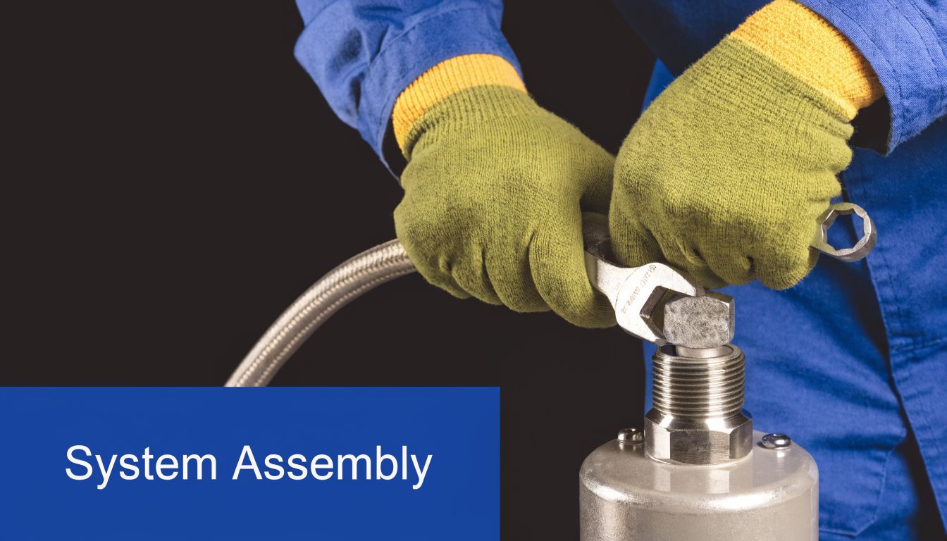
Assembling Your Power Pack
A power pack usually earns its reputation in the workshop before it ever reaches site. I have seen neatly painted units fail in the first week because the suction line was strained, the coupling was misaligned, or a return filter was fitted where no one could service it. Assembly decides whether the design on paper will survive real duty.
Build around alignment, access, and cleanliness
Start with the reservoir and baseframe. Check that the mounting faces are flat, the frame is not twisted, and the tank has been cleaned properly after fabrication. Swarf, weld scale, and paint debris are still among the most common causes of early valve and pump trouble on new packs.
Mount the motor, bellhousing, coupling, and pump as one assembly, then confirm the shafts are sitting where the coupling manufacturer intended. Bellhousings and claw couplings are popular in UK workshop builds for good reason. They speed up assembly and, if sized correctly, keep alignment under control. Get this wrong and you usually pay for it through worn coupling spiders, noisy bearings, and leaking pump shaft seals.
A few workshop checks save a lot of grief later:
- Trial-fit the drive set dry before final tightening, so shaft engagement and coupling clearance are confirmed.
- Tighten motor and bellhousing fixings evenly to avoid pulling the pump off centre.
- Support manifolds, coolers, and heavier valve stations properly so pipework is not carrying dead weight.
- Keep service space around breathers, fillers, filters, gauges, and terminal boxes. If a filter bowl cannot be removed in the workshop, it certainly will not be easy beside a press or on a mobile machine.
Pipe the unit like it will be repaired one day
The drawing defines the circuit. The assembly has to make that circuit workable.
Keep suction lines short, full-bore, and well sealed. Long or undersized suction runs can make a perfectly good gear pump sound rough and wear early. On many compact UK industrial packs, the temptation is to squeeze components tightly to reduce footprint. That saves space, but it can make hose replacement, filter changes, and fault-finding far harder than they need to be.
Route hoses and tube runs so they sit naturally without being forced into place. A hose under twist will usually tell you later through weeping fittings or cover wear. Protect against rubbing points, leave room for movement, and clamp lines where vibration would otherwise work on the fittings. On mobile packs used on tippers, small plant, or agricultural attachments, this matters even more because shock loading and chassis movement are part of normal service.
Set the relief arrangement to suit the machine duty, not workshop guesswork. A pack for a small clamp circuit, a dock leveller, and a bespoke factory jig may all use similar core parts, but the pressure settings, flow stability, and heat load will differ.
Wire for the duty, not just the bench test
Electrical assembly changes with the application.
For a fixed industrial pack, the usual priorities are three-phase motor rotation, overload protection, isolators, tidy control wiring, and an enclosure that stands up to the environment. A pack beside a saw line or recycling plant in the UK often needs more attention to dust, washdown risk, and cable protection than a clean indoor test bay suggests.
For a 12V or 24V DC mobile unit, current draw and voltage drop become the first checks. Undersized cable can make a healthy motor look weak. Poor earthing can create faults that appear hydraulic but are electrical. Solenoid coils also need to match duty cycle. A valve that works for brief intermittent use on a tail lift may not suit repeated operation on a hard-worked trailer or service vehicle.
This walkthrough gives a useful visual reference for the physical side of assembly:
Assemble with compliance and efficiency in mind
Good assembly also supports compliance later. If the pack will go into UK workplace service, label components clearly, protect rotating parts, and make isolation points obvious. If the vessel, accumulator, or pressure-bearing parts bring PED questions into scope, keep the build traceable from the start. It is much easier to document components, pressure ratings, and settings during assembly than to reconstruct them after the unit is finished.
Energy use starts here as well. A power pack built with poor hose sizing, unnecessary pressure loss, or a motor that runs continuously against relief will cost more to operate and run hotter than it should. MA Hydraulics commonly sees this on replacement jobs where the original unit was assembled to fit a footprint rather than the duty.
Finish it as if another technician will inherit it
Before filling with oil, inspect the pack as a service engineer would.
Check that:
- Fasteners are torqued to workshop standard
- Ports and test points are clearly identified
- Drain, fill, breather, and filter access is unobstructed
- Electrical terminals are covered and marked
- Hoses and cables are clipped, separated, and protected from abrasion
- Tank internals such as suction strainers, return arrangements, and baffles are fitted as intended
A power pack that is easy to inspect and service usually lasts longer, runs cleaner, and causes fewer callouts.
Commissioning, Testing, and UK Compliance
A power pack earns its place on site during commissioning, not on the bench. I have seen tidy-looking units fail in the first hour because the motor rotation was wrong, the relief valve had been wound in too far, or air had been left trapped in a vertical cylinder line. The build phase proves you can assemble it. Commissioning proves you understand how it will behave under pressure, heat, and real duty.

Commission the unit methodically
Start with the basics that prevent avoidable damage. Fill with the specified oil, confirm the suction line is open, check the return path to tank, and jog the motor to verify rotation before you let it run. On a UK industrial three-phase supply, swapped phases still catch people out.
Bring the unit up in stages. Keep the first run as unloaded as the circuit allows so the pump can prime and circulate oil without hitting full pressure straight away. Bleed air at the highest points or through controlled actuator cycling, and watch for foam, chatter, or erratic cylinder movement. Those are early signs that the pump is drawing air, the return is aerating the tank, or a hose connection is not as sound as it looked during assembly.
Set and test with instruments, not guesswork:
- Check standby and working pressure with a calibrated gauge or digital test kit.
- Set the main relief valve against a known value and record the final setting.
- Monitor oil temperature through the initial run to spot bypass heating, undersized return filtration, or excessive pressure loss.
- Inspect every joint under pressure for weeping, movement, and hose twist.
- Cycle all functions repeatedly to confirm stable operation, repeatable speed, and acceptable noise level.
A short pressure test and a quick visual check are not enough on a custom unit. The pack needs to hold pressure, return oil cleanly, and run without abnormal heat build-up. On a compact mobile pack, that usually means paying close attention to reservoir size and cooling margin. On a fixed industrial unit, poor unloading strategy or a motor running continuously across the relief valve is the usual source of heat.
PUWER and PED apply to the finished assembly
In the UK, a hydraulic power pack used at work falls into the same conversation as the machine it serves. PUWER requires work equipment to be suitable, maintained, and safe to use, and the legal text is easy enough to check in the Provision and Use of Work Equipment Regulations 1998 on legislation.gov.uk. If you are supplying or substantially modifying a unit, you also need to consider whether pressure equipment duties apply to the assembly, the accumulator set, or other pressure-containing parts under the Pressure Equipment (Safety) Regulations 2016.
That has practical consequences in the workshop. Guards around couplings and rotating parts need to be fitted. Pressure settings need to be documented. Hoses, manifolds, accumulators, and valves need pressure ratings that match the actual duty, not the hoped-for duty. If the pack is going onto a factory line, a waste baler, a vehicle lift, or a tipping trailer, the compliance file needs to reflect the application rather than sit as a generic folder.
What good testing and compliance look like in practice
For MA Hydraulics jobs, the paperwork is part of the engineering. A sensible handover pack includes the hydraulic schematic, electrical information, component list, pressure settings, test results, and safe isolation procedure. Traceability matters most when the unit comes back in two years later for a valve change or fault find. Without records, a simple service call turns into reverse engineering.
The same applies to efficiency. Commissioning is the point where you find out whether the pack is wasting power through constant relief flow, overspeeding actuators, or running hotter than the duty cycle justifies. That matters on UK sites where electricity cost is under scrutiny and where a cooler, VSD-driven motor package, or load-sensing arrangement may repay the extra upfront cost.
A compliant power pack is one that can be tested, understood, and operated safely by the next technician who touches it. That standard is higher than “it runs”, and it should be.
Long-Term Care and Expert Support
A well-built power pack will only stay reliable if someone looks after it properly. Most failures don't arrive without warning. The oil gets hot. The filter condition worsens. A hose starts rubbing. A coupling gets noisier. A pressure setting drifts. Good maintenance catches those signs before they turn into downtime.
Keep the basics under control
Routine care should stay simple and disciplined:
- Check fluid level and condition. Dirty, aerated, or overheated oil tells you something is wrong upstream.
- Watch operating temperature. Heat is usually a symptom, not the root cause.
- Inspect filters and breathers. If contamination gets in, every other component pays for it.
- Examine hoses and fittings for abrasion, sweating, or movement at clamps and supports.
- Listen to the pack. Pumps, couplings, and relief valves often change sound before they fail.
Build for service, not just for delivery
The best custom units are easier to maintain because the engineer planned that from the start. Gauges are accessible. Filters can be changed cleanly. Valves can be traced. The reservoir can be drained and cleaned without dismantling half the machine.
That's why the full process matters. Good calculation prevents poor performance. Correct component sizing prevents chronic overheating. A proper schematic prevents assembly errors. Careful commissioning prevents hidden faults going straight into production. Compliance protects the operator and the business.
If you're working through how to make hydraulic power pack assemblies for a real machine, there's a point where a quick answer over the phone can save days of trial and error.
For application advice, component matching, or a bespoke unit, contact MA Hydraulics Ltd. Phone 01724 279508 today, or send us a message through the contact form.
