
If you're specifying a hydraulic power pack right now, you're usually under pressure from two directions at once. The machine has to do a very clear job, but the space, duty, controls and budget rarely line up neatly. That’s where good hydraulic power pack design earns its keep. It turns a vague requirement like “lift faster”, “hold pressure”, or “run two functions together” into a unit that works reliably on the shop floor, on a tractor, or on a production line.
Most problems don’t start with exotic failures. They start with ordinary decisions made too early. A pump is chosen before the load is understood. A tank is squeezed to fit a frame. A valve is picked because it’s available, not because it suits the circuit. Months later, the same system is hot, noisy, awkward to service, or forever tripping the relief.
A sound design process avoids that. In practice, the strongest results come from working backwards from the application, then building the pack around real operating conditions rather than catalogue assumptions.
From Concept to Core The Foundation of Power Pack Design
A hydraulic power pack exists to deliver controlled force and motion where direct mechanical drive would be clumsy, bulky, or inflexible. That sounds simple, but it changes the design mindset. You’re not buying a motor and pump. You’re creating a power source for a specific machine behaviour.
A bespoke unit often makes more sense than an off-the-shelf pack when the machine has awkward mounting limits, unusual control requirements, intermittent but high load demand, or a duty cycle that doesn’t fit a generic unit. In those cases, standard packs tend to be either too small in the wrong places or oversized in the expensive ones.

Why the application matters more than the catalogue
A workshop press, a mobile tipper and a clamping station might all use hydraulic power, but they don’t ask the same things of a pack. One may need short bursts at higher pressure. Another may need compact installation and simple DC control. Another may need steady repeatability and clean operation in a manufacturing environment.
That’s why the first question isn’t “Which pump?” It’s “What must the machine do, every shift, in real conditions?”
Practical rule: A power pack should be designed around the load, speed, environment and service access. If any of those are guessed, the rest of the build usually chases the wrong target.
British engineering roots still shape modern builds
Hydraulic power pack design in the UK has deep roots. Joseph Bramah, a British engineer, patented the hydraulic press in 1795, applying Pascal’s Law to multiply force through confined fluid. William George Armstrong advanced hydraulic power in 1850 with the hydraulic accumulator, helping establish the groundwork for modern hydraulic power networks, as noted in this historical perspective on hydraulic system design.
Those early systems solved a problem that still matters now. They delivered substantial force in a controlled, distributed way without relying on bulky mechanical linkages. The modern power pack follows exactly the same logic. Put the energy source where it suits the installation, control it properly, and send hydraulic power where the work happens.
That heritage still shows in British machine building. Compact packs, modular manifolds, serviceable valve arrangements and practical layouts aren’t trends. They’re the continuation of a long engineering habit of making systems work in practice, not just on paper.
Defining Your Application Requirements
The discovery stage decides whether the finished pack feels sorted or compromised. If the brief is loose, the design ends up full of assumptions. If the brief is tight, the component choices become much clearer.
Start with the machine function, not the component list. “Raise a platform” isn’t a complete requirement. You need to know how much force is needed, how quickly it must move, how long it will run, what control feel is expected, and what happens when the machine reaches end of stroke or stalls.
The questions that shape the pack
Some requirements are obvious. Others are the ones that usually get missed until late in the job.
- Load requirement. Define the actual force or torque needed at the actuator, not a rough guess.
- Movement requirement. Record the stroke, speed, cycle time, and whether motion must be smooth, fast, synchronised, or finely controlled.
- Duty pattern. Note whether the pack runs occasionally, repeatedly, or for extended periods.
- Installation limits. Capture footprint, height, mounting orientation and access for servicing.
- Environment. Consider dirt, washdown, outdoor exposure, ambient temperature and vibration.
- Control method. Decide whether the machine needs simple on/off control, proportional response, remote operation, or manual override.
- Fluid and compatibility. Fluid choice affects seals, filtration, contamination control and environmental precautions.
If the system sits near chemical storage, drainage channels, or process areas where fluid containment matters, it’s worth thinking about bunding and material compatibility early. The same thinking used when choosing the right chemical storage tank for your facility applies here as well. Containment, access and compatibility should be designed in from the start, not patched in later.
What a usable technical brief looks like
A good brief doesn’t need to be complicated. It needs to be complete enough that someone selecting pumps, motors, valves and tank size isn’t forced to fill in the gaps.
| Parameter | Value / Description | Unit |
|---|---|---|
| Machine / function | ||
| Actuator type | Cylinder, motor, clamp, lift, press, tipper, other | |
| Required force / torque | bar / Nm / kN as applicable | |
| Stroke or displacement | mm / cc | |
| Target speed / cycle time | mm/s / s | |
| Number of functions | ||
| Simultaneous functions | Yes / No, with notes | |
| Duty cycle | Intermittent / repeated / extended run | |
| Prime mover | AC motor, DC motor, engine | |
| Supply available | Voltage / phase / site constraints | |
| Control method | Manual, solenoid, proportional, remote | |
| Mounting orientation | Horizontal / vertical / enclosed / mobile | |
| Space envelope | Length × width × height | mm |
| Operating environment | Indoor, outdoor, dirty, wet, corrosive | |
| Ambient temperature | °C | |
| Fluid type | Mineral oil / biodegradable fluid / other | |
| Filtration expectation | Standard or higher cleanliness requirement | |
| Noise sensitivity | Low / medium / high | |
| Service access notes | Filter access, filler access, hose routing | |
| Safety requirements | E-stop, hose burst protection, holding valves, guarding | |
| Compliance requirements | Site or industry specific |
The cleanest hydraulic power pack design jobs are the ones where the machine builder can answer operational questions before anyone opens a component catalogue.
Where under-specifying causes trouble
Three areas tend to create avoidable rework.
First, people understate startup load. A mechanism that moves easily once in motion may need much higher breakaway force. Second, they ignore what happens when more than one function runs together. Third, they leave out service conditions, which leads to cramped filler access, impossible filter changes, and hose routes nobody wants to maintain.
A complete brief prevents all three. It also makes procurement easier because every quotation is being compared against the same real requirement, not a slightly different interpretation.
Calculating Core Power and Flow Rates
A pack that looks fine on a quotation can still fail on the shop floor. The usual pattern is simple enough. The cylinder moves in test, but under real load it slows, the motor labours, oil temperature climbs, and the relief valve spends too much of its life open. Good sizing work prevents that.
Pressure sets the available force. Flow sets actuator speed. Motor power has to cover both at the actual operating point, not a convenient theoretical one.
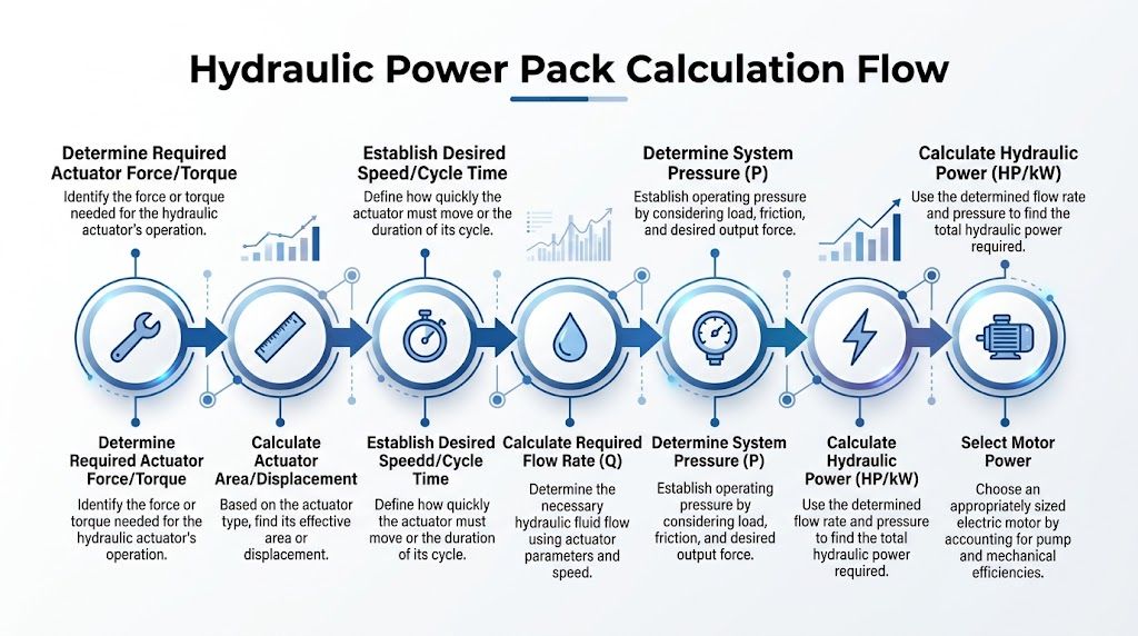
Start with force and actuator area
For a cylinder duty, required pressure comes from force divided by effective piston area. On the bench, that is straightforward. On a British OEM machine with real hose runs, valve stations, manifolds and cold-start conditions, it is never the full story.
The circuit needs allowance for pressure loss through pipework and components, plus a sensible design margin for the actual duty cycle. BS ISO 4413 guidance from the British Standards Institution is the right reference point here because it frames hydraulic systems as assemblies that must be designed for safe operation, expected loads and foreseeable misuse, not just ideal calculations.
In practice, I size from the loaded condition, then check what happens at breakaway, at low ambient temperature, and at the end of hose life rather than the day the machine leaves the factory. That usually tells you more than a neat pressure figure on its own.
Then calculate the speed demand
Once target actuator speed is fixed, flow follows. For cylinders, that means area multiplied by speed. For motors, it means displacement and rpm. Either way, the number has to come from the machine function.
Operator expectation matters here. A clamping circuit may accept a quick approach and a slower working stroke. A lifting or positioning function may need steadier motion and finer control. One pump sized around a single headline speed often gives a poor result, especially where two functions can run together.
For multi-function packs, base the flow calculation on the services that can operate at the same time. Then check whether the electrical supply, tank size, valve stack and cooling arrangement still make sense. This is often where a standard hydraulic power unit configuration starts to diverge into a bespoke build.
A simple worked example
Take a press application. The machine needs a set forming force and a reasonable extension speed, but there is no value in fitting a motor that is larger than the site supply or duty cycle justifies.
The calculation path is usually:
- Set the required cylinder force from the tooling or process.
- Confirm the effective cylinder area from the bore and rod size.
- Calculate the working pressure from force divided by area.
- Add realistic pressure loss and operating margin for the circuit layout.
- Set the target speed for approach and working stroke.
- Calculate the flow needed at each stage.
- Size the motor from the pressure and flow combination at the true duty point.
That last step catches a lot of weak designs. A pump may meet the speed target on paper, but if the motor is too small for the loaded pressure-flow requirement, the pack runs hot, stalls under peak demand, or hammers oil across the relief valve.
Do not overspecify pressure and starve the machine of flow
Higher pressure is often treated as a safety blanket. In practice, it can be a costly distraction. If the cylinder area is wrong or the pump flow is too low, the machine will still feel slow and strained.
A better design question is this. Where does the machine spend most of its working life? If it spends seconds at peak pressure and hours cycling at modest load, size the motor and pump around that reality, then check the short-duration peak against allowable limits.
This matters with UK power supplies. A 3-phase industrial site may comfortably support one motor size, while a mobile or light industrial installation may force a different approach using lower speed, accumulator support, or staged functions. Brand choice comes into it as well. We often pair Italian pump and power unit components from Vivoil or Hydronit with a circuit built around the available electrical and space constraints, because sourcing, service parts and delivery times matter just as much as the maths.
Match the components as a system
Pump, motor, relief setting and cooling arrangement have to be selected together. A gear pump that is happy at one pressure range may be the wrong choice if the duty sits near the top of its operating envelope for long periods. The same applies to motor selection. Intermittent duty can justify a smaller installed power than continuous heavy cycling, but only if the thermal side has been checked properly.
The practical target is a pack that starts cleanly, holds pressure without fuss, and runs within temperature limits through a real shift. That is the standard British OEMs and MRO teams usually need. It is also why sound hydraulic power pack design depends on UK supply realities, BS/ISO compliance, and parts you can still source and support two years from now.
Sizing Key Ancillaries and Control Systems
A power pack that looks right on paper can still be awkward in service. The usual reason is not the pump or motor. It is the supporting hardware around them. Tank size, filtration, valve layout, cooling and instrumentation decide whether the unit runs cleanly for years or keeps coming back with heat, noise and contamination faults.
Reservoir sizing that works in practice
Reservoirs are often undersized because the machine envelope leaves little room. That compromise usually shows up later as foaming, unstable oil temperature and poor deaeration.
In UK workshop practice, a good starting point for a general industrial pack is still around three times pump flow per minute, then adjusted for return line arrangement, duty cycle, ambient temperature and the actual free air space needed above the oil. We also leave sensible allowance for expansion, level switch hysteresis and maintenance top-up. A 50 L/min pack will often land somewhere around 150 litres, but that is only a starting point, not a rule that overrides the duty.
The tank has jobs to do. It must separate entrained air, let contamination settle, support heat rejection and feed the pump inlet without turbulence. If the return drops straight onto the suction zone, or the baffle arrangement is poor, a larger tank will not fully rescue the design.
For OEMs trying to reduce footprint, I would usually shrink the reservoir only after checking whether an oil cooler, better internal baffling or an offline filter circuit can carry the load without shortening oil life.
Filtration needs to match the circuit, not a catalogue default
Contamination control is where many otherwise decent packs go wrong. A pressure line filter fitted purely because there was space on the manifold is not a filtration strategy.
The cleaner target has to match the most sensitive component in the circuit. Bosch Rexroth's guidance on fluid cleanliness classes and component sensitivity is useful here because it ties cleanliness to valve and pump life rather than treating filtration as a generic add-on. That matters on packs using proportional or cartridge control, where small particles can create faults that look like electrical or control problems.
A workable arrangement usually includes:
- Suction protection used carefully, with a coarse strainer only where inlet losses remain acceptable.
- Return filtration sized for the actual return flow and dirt-holding capacity, not just the port size.
- A decent breather filter, especially on dusty sites or outdoor plant.
- Offline filtration on larger reservoirs, high-value oil volumes, or systems where uptime matters more than first cost.
The trade-off is straightforward. Finer filtration improves component life, but it also raises pressure drop, increases element cost and demands proper condition monitoring. On bespoke packs at MA Hydraulics, we normally specify clogging indicators and make element access easy, because a filter hidden behind pipework tends not to get changed on time.
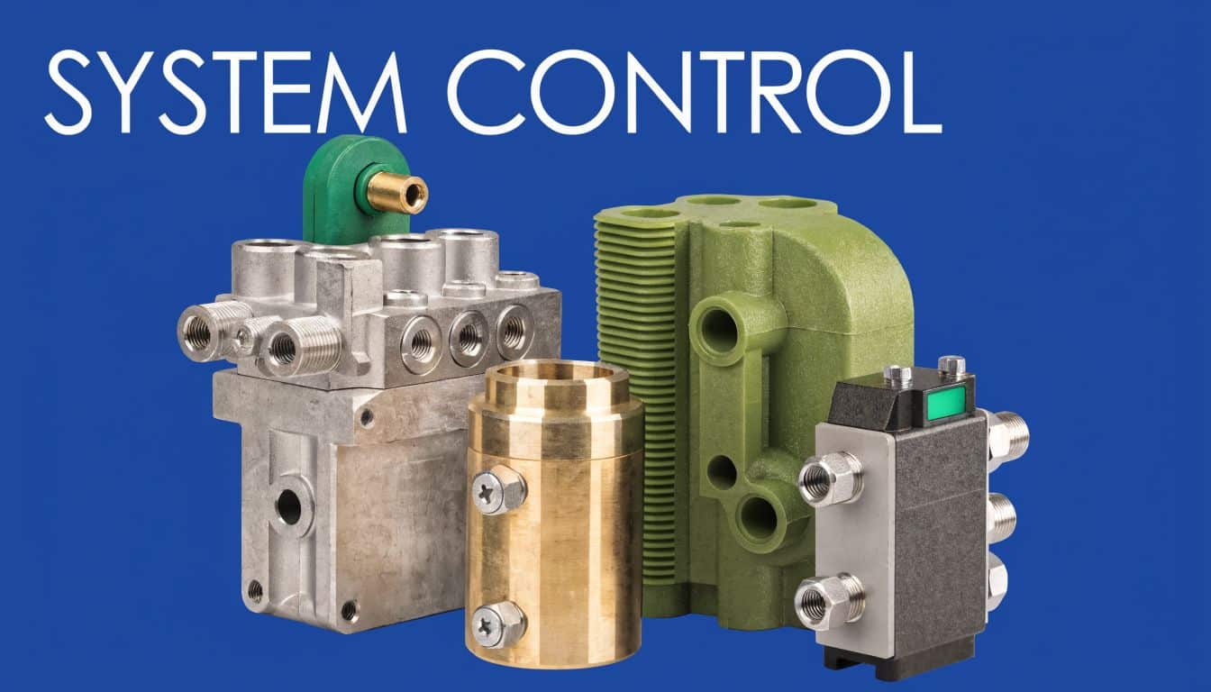
Valve choice changes machine behaviour
Valve selection affects far more than basic function. It changes motion quality, heat generation, fault-finding time and how easy the pack is to modify later.
CETOP 3 and CETOP 5 valves remain common on British industrial packs for good reason. They are easy to source, simple to manifold and straightforward for maintenance teams to replace. Once flow rises or functions multiply, cartridge manifolds often make more sense because they reduce pipework, leak paths and dead volume. They also demand better design discipline up front.
A useful reference point is this overview of hydraulic valve types and their practical uses, particularly when choosing between simple directional control, modular stack valves and pressure control options.
Here is the practical trade-off:
| Component | What it does well | Where it causes trouble |
|---|---|---|
| Pressure relief valve | Protects the system from overload and pressure spikes | Poor setting or frequent cracking wastes power and creates heat |
| Directional valve | Controls actuator movement with simple serviceable hardware | Wrong spool or poor shift characteristics can make motion harsh |
| Flow control valve | Gives simple speed control on predictable loads | Throttling excess flow creates heat and hides sizing errors |
| Pressure-compensated valve | Holds steadier performance as load changes | Higher cost and more sensitivity to contamination |
If actuator speed varies badly with load, the answer is often a different control method, not another turn on the relief valve.
Cooling, instrumentation and layout decide whether the design is serviceable
Thermal problems usually start with layout. Tight tanks, short oil dwell time, relief losses and poor return routing will push oil temperature up long before anyone asks for a cooler.
Parker's guidance on reservoir and thermal management in hydraulic systems is a useful reminder that heat has to be removed by the whole arrangement, not by one accessory bolted on at the end. In practice, we check pipe bore, return entry position, cooler bypass strategy and the actual fouling conditions around the heat exchanger. A cooler mounted where dust and chaff block the matrix is a maintenance item disguised as a design feature.
Instrumentation is part of the same job. Pressure test points, clogging indicators, temperature switches, sight gauges and sensible level monitoring save hours during commissioning and fault finding. British MRO teams value that more than a neat-looking pack with no access to the information they need.
Where packs sit in shared factory areas or on mobile equipment, clear labelling also matters. Good industrial safety signage helps maintenance staff isolate stored energy correctly and reduces the chance of the wrong valve or test point being touched during service.
Brand choice sits underneath all of this. We regularly specify Vivoil and Hydronit where their format, availability and support suit the application, but the circuit always comes first. For UK OEMs, that balance between performance, compliance, lead time and spare parts support is often what separates a tidy build from a reliable one.
A short visual overview can help when discussing control arrangements with non-hydraulic colleagues:
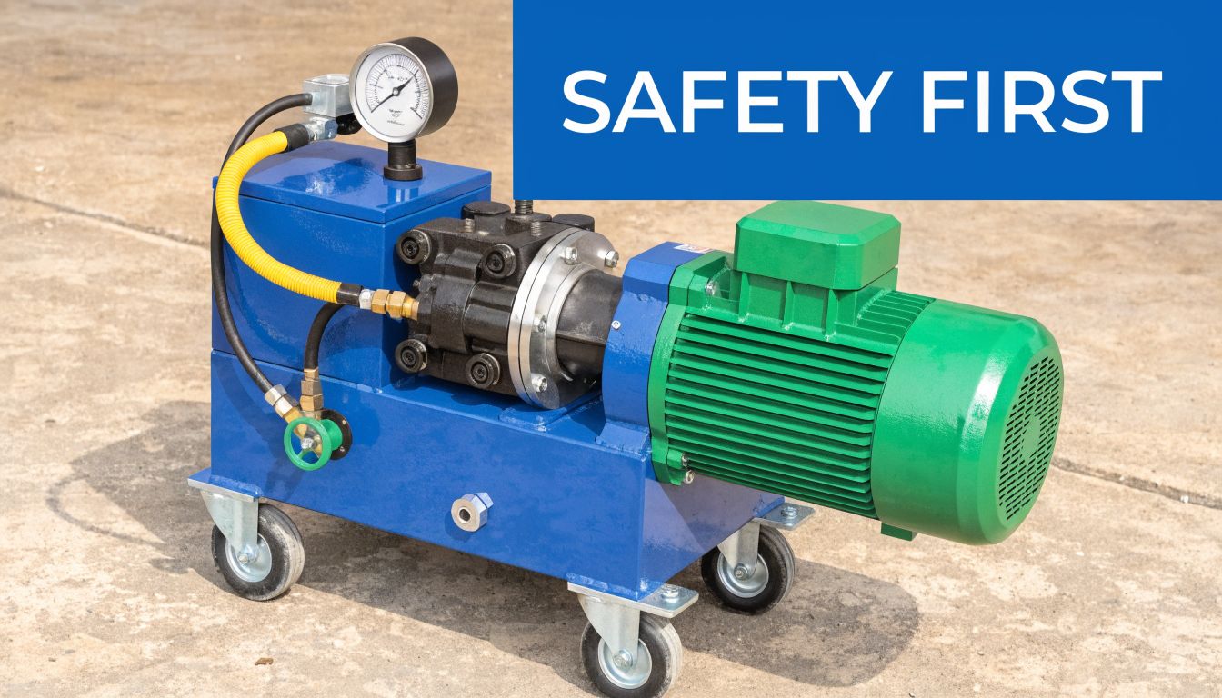
Ensuring Safety Compliance and Practical Layout
A hydraulic power pack can be mathematically correct and still be poor engineering if it’s unsafe to run, awkward to install, or messy to maintain. Safety and layout should be part of the design from the first drawing, not the final snagging list.
Compliance affects physical design choices
In UK practice, BS ISO 4413:2010 is a key reference point for hydraulic fluid power safety and general system design, and it should influence how you approach hose routing, pressure protection, reservoir design, emergency stops and maintenance access. Good compliance work doesn’t just satisfy paperwork. It usually improves the build.
Environmental compliance has become impossible to ignore. Under the Environmental Permitting Regulations 2016, hydraulic oil spills are treated as polluting incidents. The UK Environment Agency recorded 1,247 hydraulic oil pollution events in one year, with fines averaging £15,000 per breach, making leak prevention and bunding commercially sensible as well as responsible, according to this hydraulic power pack configuration guide covering UK spill rules.
The same source notes that bunded reservoirs and secondary containment are mandatory for sites over 500 litres, and references HEES biodegradable oils per ISO 15380 plus ATEX-rated components for Zone 2 areas where the application requires them. It also states that switching to bio-oils can reduce spill fines, while adding upfront cost.
Practical layout decisions that save trouble later
A clean layout starts with separation of functions. The filler and breather need safe access. Filters must be reachable without dismantling half the frame. Pressure gauges should be visible. Relief valves should be adjustable without forcing a technician to work around hot surfaces or rotating guards.
A few layout decisions consistently pay off:
- Keep suction lines short and calm. This helps protect pump inlet conditions.
- Use manifolds where they reduce leak points. A well-planned manifold block often beats a tangle of adaptors and hoses.
- Leave service space around filters and electrical items. If access is poor, routine maintenance gets skipped.
- Manage heat paths. Don’t trap hot air around the motor and tank.
- Mount for vibration control. A neat frame and proper damping protect pipework, electrics and fittings.
The easiest pack to maintain is usually the one that was easiest to draw clearly. If the schematic is confused, the layout often is too.
Safety communication on the machine matters too
Even a well-designed pack still relies on people using it correctly. Clear labels, warning points, operating instructions and isolation notices make a real difference during service and handover. For firms reviewing what clear visual risk communication looks like in industrial settings, examples of industrial safety signage are useful because they show how hazard information can be made visible and unambiguous around operating equipment.
That same principle applies to hydraulic packs. Isolation points, pressure warning labels, hot surface notices and emergency stop identification should be obvious, durable and placed where operators and fitters will clearly see them.
Commissioning Testing and Long-Term Maintenance
A newly built power pack shouldn’t go straight from assembly to full load. Commissioning is where you confirm that the machine behaves like the schematic said it would. It’s also where small issues are cheapest to fix.
Start with the fundamentals. Check oil level, verify hose routing, confirm all fittings are tightened correctly, and make sure the motor rotation is right before asking the pump to do real work. Jogging the motor briefly can prevent a lot of grief if the rotation has been wired incorrectly.
A sensible commissioning routine
The first startup should be controlled and deliberate, not rushed because production is waiting.
- Verify mechanical assembly. Guards fitted, coupling aligned, mounts secure, hoses supported.
- Confirm electrical setup. Rotation, controls, interlocks and emergency stop function.
- Prime and jog carefully. Avoid running the pump dry.
- Bleed air from the circuit where required. Air in the system distorts behaviour and raises noise.
- Set the relief valve correctly. The Hydrastore guidance already noted a practical setting of 1.1x maximum load in the context of specification errors in reservoir and circuit design, as cited earlier.
- Bring pressure up gradually. Watch gauges, sound and temperature.
- Inspect for leaks under pressure. Static checks aren’t enough.
- Cycle every function repeatedly. Confirm speed, sequencing and end-of-stroke behaviour.
A good commissioning sheet should record final relief settings, fluid type, filter type, motor data, and any observations made during the first loaded cycles.
Maintenance that prevents expensive surprises
Hydraulic systems reward routine attention. They punish neglect slowly at first, then all at once.
A practical maintenance rhythm looks like this:
| Interval | Check | Why it matters |
|---|---|---|
| Daily | Oil level, obvious leaks, unusual noise | Finds simple faults before they become damage |
| Weekly | Hose condition, mountings, electrical cable security | Catches wear and vibration issues early |
| Monthly | Filter indicators, breather condition, general cleanliness | Helps control contamination and airflow |
| Periodic planned shutdown | Coupling condition, relief stability, valve function | Confirms the pack is still operating as designed |
| Annual or condition-based | Oil assessment, tank cleanout if required, cooler inspection | Restores system condition and removes accumulated contamination |
What usually shortens service life
Most long-term issues can be traced back to four causes. Contamination, heat, aeration and incorrect settings. That’s why commissioning and maintenance aren’t separate topics. A poor startup often creates a recurring maintenance problem that nobody links back to the original build.
If a pack starts to run hotter, louder or slower than it did at handover, don’t treat that as normal ageing. It usually means oil condition has changed, a filter is restricting flow, the relief is passing too often, or wear is increasing internal leakage. Good records make those patterns visible.
Your Partner in Hydraulic Power Pack Design
Good hydraulic power pack design is disciplined engineering. The successful units are rarely the most complicated. They’re the ones where the brief was clear, the calculations were grounded in real duty, the reservoir and filtration were not treated as afterthoughts, and the final layout made sense for both operation and service.
That’s why details matter. A correctly matched gear pump, a valve arrangement that suits the motion you need, and a serviceable manifold layout will usually outperform a more expensive pack built around assumptions. The aim isn’t to chase specification for its own sake. It’s to deliver dependable hydraulic power with manageable heat, clean oil, safe operation and sensible maintenance access.
For businesses that need support beyond component supply, fluid power services from MA Hydraulics cover the practical side of specification, component matching and bespoke hydraulic assembly for mobile and industrial applications. That’s useful when the job involves unusual duty, legacy equipment, hard-to-find parts, or a pack that has to fit a machine rather than the other way round.
If you're planning a new build, replacing an unreliable unit, or trying to correct a design that never quite worked properly, it pays to slow the decision down and get the fundamentals right. A hydraulic power pack is not just a purchased item. It’s a working asset that should give years of reliable service when it’s designed, commissioned and maintained properly.
If you need help with a bespoke hydraulic power pack, component selection, or a full hydraulic system build, contact MA Hydraulics Ltd. Phone 01724 279508 today, or send us a message to discuss your project.
