If you are replacing a failed pump, sizing a new power pack, or trying to stop a machine from eating seals and overheating oil, the same issue usually sits underneath it all. The pump was either badly matched, badly installed, or forced to run in conditions it should never have seen.
Gear hydraulic pumps are popular because they are straightforward, compact, and dependable when the basics are right. They are also unforgiving of poor suction conditions, dirty oil, wrong rotation, and casual parts matching. In workshops and on mobile machinery, most expensive failures are not mysterious. They start with small decisions made too quickly.
For UK industry, agriculture, plant, and materials handling, gear pumps remain a core technology. The wider UK hydraulic components market was valued at approximately £450 million in 2023, with gear pumps accounting for around 40% of that market due to their strength in mobile applications, according to hydraulic gear pump market reporting. That tells you how often engineers still choose them when reliability, packaging, and cost matter.
How Gear Pumps Create Hydraulic Flow
A gear pump does not create pressure by itself. It creates flow. Pressure appears when that flow meets resistance from the rest of the circuit, such as a cylinder under load, a motor driving a conveyor, or a relief valve setting.
The easiest way to picture it is two water wheels turning inside a close-fitting housing. As the gears come out of mesh on the inlet side, they open up volume. That increase in volume lets oil enter the pump. The oil is then carried around the outside of the gears, between the gear teeth and the housing, until the teeth mesh again on the outlet side and push the oil out into the system.
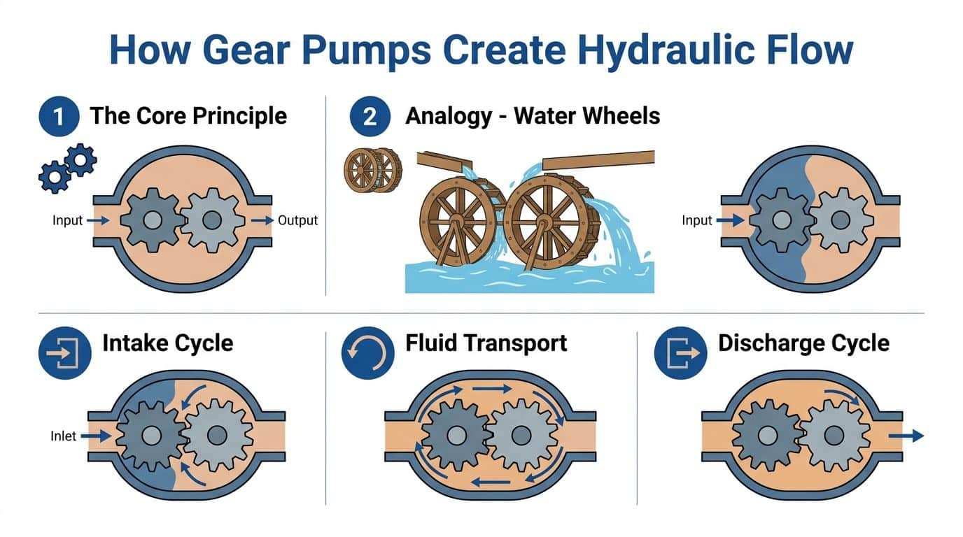
The positive displacement principle
Gear hydraulic pumps are positive displacement pumps. That means every revolution moves a fixed volume of oil, subject to normal internal leakage.
That fixed-volume behaviour is why they are so useful in machines:
- Predictable flow: If you know the pump displacement and shaft speed, you can estimate output flow.
- Simple control: They suit systems where you want dependable, repeatable flow without a complicated variable pump arrangement.
- Compact packaging: They fit well on PTOs, engine-driven packs, mini power units, and industrial skids.
What they do not like is being treated like a centrifugal pump. Restrict the inlet, run the oil too cold, let air into the suction line, or overspeed the shaft, and the pump will tell you quickly through noise, heat, or falling performance.
External and internal designs
In UK mobile and industrial work, the pump you will see most often is the external gear pump. It uses two external gears of equal size. One gear is driven by the shaft, and that gear turns the other. These pumps are common because they are mechanically simple, compact, and well suited to a wide range of machinery.
Internal gear pumps use an inner gear rotating inside a larger outer gear. They can offer smoother flow and are used in some specialist duties, but for many agricultural, plant, and general hydraulic power applications, the external type remains the practical choice.
Practical point: When engineers say “gear pump” in day-to-day hydraulic work, they usually mean an external gear pump unless they specify otherwise.
Why the housing matters
The pump only works properly because the clearances inside it are controlled tightly. The housing, side plates, bushes, and gear tooth geometry all help limit internal leakage. Once wear opens those clearances up, flow slips backwards internally instead of going to the actuator. The machine then feels weak or slow, even though the prime mover is still turning the pump.
This is also why clean oil matters so much. Tiny abrasive particles do not need long to score side faces and increase leakage paths.
The basic idea of the gear pump goes back a long way. The concept emerged around 1600 with Johannes Kepler’s design and was advanced in 1636 by Pappenheim’s double deep-toothed rotary gear pump, developments that helped lay foundations for later UK hydraulic use, including after Joseph Bramah’s 1795 hydraulic press patent, as outlined in this history of pump development.
Selecting The Right Gear Pump For Your Application
Pump selection starts with the machine, not the catalogue. Too many problems begin with someone matching only the port size or only the old part number. A pump has to suit the duty, the drive, the oil, the mounting, and the circuit.
Start with four questions. What flow do you need. What pressure will the machine operate under. What speed will drive the pump. Is the pump required to rotate in one direction only or in both directions.
Start with flow and displacement
Flow requirement usually comes from actuator speed. If a cylinder needs to extend faster, the circuit needs more litres per minute. If a hydraulic motor needs to turn at a target speed, the same rule applies.
Pump displacement is the volume moved per revolution, normally expressed in cc/rev. A larger displacement gives more flow at the same shaft speed. A smaller pump can still do the job if it runs faster, but that only works if the inlet conditions and pump speed rating allow it.
A useful example comes from the Casappa KAPPA series. These pumps are available from 4.95 to 180.73 cc/rev and can reach peak pressures up to 330 bar (4785 psi), with cast iron construction chosen for reliability and temperature tolerance in demanding duties, according to Casappa gear pump specifications.
Pressure is not a guess
Pressure rating must be based on the machine's true load, not a hopeful estimate. Relief valve setting matters, but so do shock loads, starting loads, and what happens when an operator hits end of stroke or stalls a driven function.
If the application is a lightly loaded conveyor, the pressure demand will be very different from a compact hydraulic pack feeding a clamp, lift, or agricultural function that regularly works against resistance. Choose a pump with enough pressure capability for normal operation and sensible margin for the system it is entering.
Group size and physical fit
Group 0 to Group 3 pumps are common in UK mobile and industrial machinery. The group gives you a practical clue about physical envelope, shaft size, mounting style, and likely flow range.
Use the table below as a working guide, not a substitute for the manufacturer’s drawing.
| Pump Group | Typical Displacement (cc/rev) | Typical Max Continuous Pressure (bar) | Common Applications |
|---|---|---|---|
| Group 0 | Small | Lower to medium duty | Compact power packs, auxiliary circuits, small mobile equipment |
| Group 1 | Small to medium | Medium duty | Mini power units, light industrial machinery, agricultural auxiliaries |
| Group 2 | Medium | Medium to higher duty | Tippers, materials handling, mobile plant, general industrial systems |
| Group 3 | Medium to large | Higher duty | Heavier mobile plant, industrial packs, higher flow circuits |
Mounting, shaft, and port details
Most replacement headaches come from mechanical mismatch, not hydraulic theory.
Check these before ordering:
- Mounting flange: UK 4-bolt, European standards, SAE patterns, and proprietary faces all appear in service work.
- Shaft type: Parallel keyed, splined, tapered, and tang shafts are not interchangeable.
- Port orientation: A pump that physically bolts on may still clash with hose runs or frame members.
- Rotation: Standard unidirectional pumps and reversible pumps serve different duties.
- Seal and material compatibility: Important if the machine runs outside standard mineral oil service.
A pump that “almost fits” usually becomes a pump that fails early.
Workshop rule: Match the drawing before the pressure rating. A stronger pump with the wrong shaft or wrong rotation is still the wrong pump.
Oil viscosity and operating temperature
Modern gear hydraulic pumps are sensitive to fluid condition and viscosity window. The accepted operating range cited for these pumps is 15-360 cSt and -20°C to 100°C, with performance depending heavily on fluid cleanliness and correct matching to the application, as described in gear pump design and reliability guidance.
Cold starts can make oil too thick. High bulk oil temperature can make it too thin. Both conditions shorten pump life, but in different ways. Thick oil starves the inlet and raises mechanical load. Thin oil increases internal leakage and heat.
Unidirectional or reversible
A standard unidirectional pump is correct for many fixed duties. A reversible gear pump is different. It is built so flow can reverse safely when shaft rotation reverses. That matters for some mobile circuits, steering-related functions, and specialist machinery where direction of rotation changes in use.
Do not assume a normal pump will tolerate reverse running because the shaft happens to turn the other way. If the internal design and sealing arrangement are not intended for it, it will not behave properly.
How To Read Gear Pump Performance Data
A datasheet tells you more than whether the pump bolts on. It tells you how hard the pump is working, how much flow you can expect in service, and whether the unit is being asked to operate in the sensible part of its range.
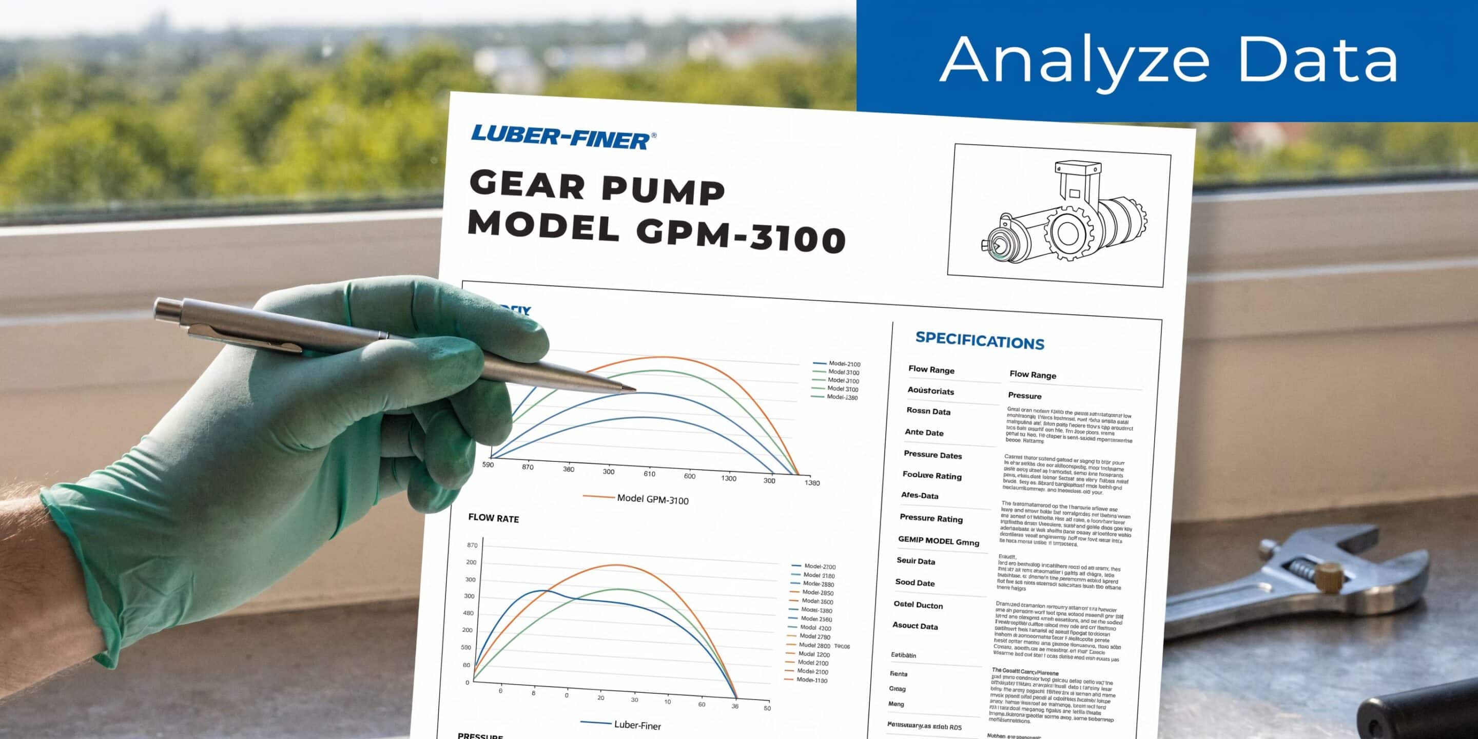
The numbers that matter first
Start with these figures:
- Displacement: The pump’s theoretical output per revolution.
- Speed range: Minimum and maximum shaft speed.
- Pressure rating: Usually split into continuous, intermittent, and peak.
- Efficiency: Volumetric, mechanical, and overall.
Modern gear hydraulic pumps operate across an efficiency range of 75-95%, with high-efficiency models at 85-95% offering clear benefits in systems such as 11 kW power packs, according to Pumps & Systems on gear pump design and operation.
What efficiency means in practice
Volumetric efficiency tells you how much of the theoretical flow leaves the outlet rather than leaking internally. If volumetric efficiency falls, the machine slows down.
Mechanical efficiency reflects friction losses inside the pump. If this falls, input power goes up and the pump runs hotter.
Overall efficiency combines both. This is the figure that matters when you are sizing the prime mover and judging heat generation in the system.
For power calculations and pressure relationships, MA Hydraulics has a useful reference on how hydraulic pressure is calculated.
Find the sweet spot
A good pump is not just one that can survive the peak number on the sheet. It is one that spends most of its life in a stable operating band.
Read the performance data like this:
- Check normal running pressure, not just relief valve setting.
- Match speed to displacement so required flow is achieved without overspeeding.
- Look at efficiency at duty point rather than at ideal lab conditions.
- Allow for oil temperature, because hot thin oil and cold thick oil both change real output.
Key takeaway: The cheapest pump on paper can cost more in service if poor efficiency adds heat, slows functions, or forces the motor to work harder.
Pressure changes power demand
As discharge pressure rises, the torque needed to drive the pump rises as well. If the electric motor or engine has no margin, the system will bog down, trip, or overheat. That is why the pump, coupling, and prime mover must be treated as one package.
In real engineering work, a slightly more efficient pump can make a clear difference over the life of a unit. Not because the brochure says so, but because lower internal loss means less wasted energy and less heat dumped into the tank.
Common Gear Pump Failures And Proactive Maintenance
Most failed gear pumps give warning before they stop. The trouble is that the warning signs are often ignored because the machine still moves.
A change in sound, more heat in the tank, jerky motion, slow functions under load, or foam in the oil are not minor details. They are early signs that the pump or the suction conditions are going in the wrong direction.

Contamination wears the pump from inside
Dirty oil is still the most common route to a weak pump. Gear pumps rely on close internal clearances. Abrasive contamination scores side faces, wears bushes, damages sealing surfaces, and increases internal leakage.
Symptoms usually include:
- Slower actuator speed: Particularly when oil is hot.
- Loss of force: The machine feels weak under load.
- Rising case and oil temperature: More energy is being lost internally.
- Metallic debris: Visible in filters or during strip-down.
High-performance gear pumps can maintain strong volumetric efficiency when built well and run correctly, but they remain dependent on cleanliness. That is why inline filtration and sensible oil handling matter more than people think.
Cavitation and aeration are different faults
These two are often confused.
Cavitation happens when the inlet side cannot supply oil properly, causing vapour cavities to form and collapse. This damages surfaces and creates a harsh rattling sound.
Aeration means air is being drawn into the oil, often from loose fittings, cracked suction hoses, poor shaft sealing, or low oil level. The oil may look milky or foamy, and operation becomes erratic.
Watch for these causes:
- Restricted suction line
- Oil too cold and too viscous
- Collapsed hose liner
- Air leak at fittings
- Low reservoir level
Overpressure and wrong rotation
A gear pump can survive hard service, but not misuse. A relief valve set incorrectly, a blocked line, or a pump run in the wrong direction can damage it quickly.
Wrong rotation is especially costly because it can look like a plumbing issue at first. The pump starts, makes noise, and fails to build normal performance. By the time the fault is recognised, internal damage may already be done.
If a unit is already showing loss of output or mechanical wear, practical repair guidance is often the next step. MA Hydraulics provides support on hydraulic pump repair.
A maintenance routine that works
Do not wait for failure. Use a simple repeatable routine.
- Check oil condition: Look for darkening, foam, haze, or burnt smell.
- Inspect filters and strainers: Restriction on the inlet side causes trouble fast.
- Listen during cold start: A pump that complains on start-up is telling you about the suction line, oil viscosity, or trapped air.
- Check couplings and alignment: Misalignment increases shaft and bush load.
- Verify relief settings after work: A replaced valve or adjusted cartridge can change the whole duty on the pump.
This video gives a useful visual overview of pump inspection and fault awareness:
Service advice: If a replacement pump fails quickly, inspect the system before fitting another one. The second pump usually fails for the same reason as the first.
A Practical Installation Checklist For Hydraulic Systems
A correctly selected pump can still fail early if the installation is careless. Most short-life units are damaged before they complete many hours of work. Dirt enters during assembly, the coupling loads the shaft sideways, the inlet line is undersized, or the pump starts dry.
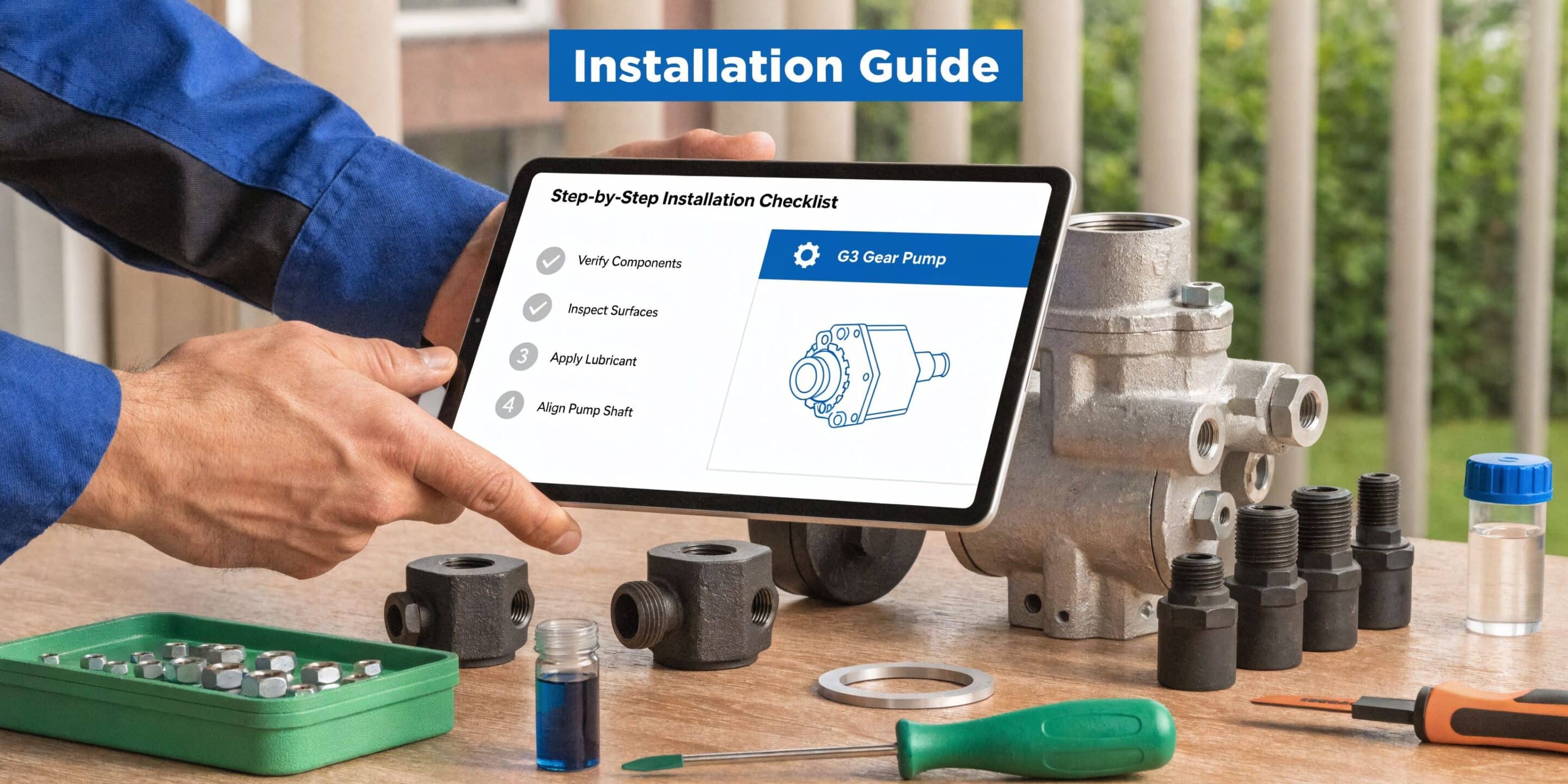
Before the pump goes on
Use a clean bench and keep protective caps in place until the last moment. A pump assembled into a dirty system will immediately circulate contamination through its working faces.
Check these first:
- Part number and rotation: Confirm against the machine and circuit drawing.
- Mounting face and shaft details: Do not force mismatched components together.
- Port cleanliness: Remove caps only when you are ready to connect clean lines.
- Drive condition: Inspect bellhousing, coupling, key, spline, and prime mover shaft for wear.
During mounting
The pump must sit squarely on the mounting face. If bolts pull the body into position, something is misaligned.
Good installation habits are simple:
- Align the shaft properly so the coupling does not side-load the pump bearings or bushes.
- Support pipework and hoses so the ports do not carry line weight or vibration.
- Use the correct suction hose size and avoid unnecessary bends, reducers, or fittings on the inlet side.
- Route return and pressure lines sensibly to reduce vibration, chafing, and heat transfer into nearby parts.
Priming and first start
Dry starts do real damage. Before first run, fill the pump if the arrangement allows it and make sure the reservoir is charged with the correct fluid.
Then follow a controlled start-up:
- Crank or jog at low speed if possible
- Loosen the circuit only where safe and appropriate to bleed trapped air
- Watch for immediate pressure response
- Listen for abnormal inlet noise
- Stop early if the pump rattles, foams the oil, or fails to pick up flow
Installation tip: The first minute of running often decides whether the pump has a long service life or a very short one.
Compliance checks for UK machinery
In the UK, component integration is not only a mechanical issue. It is also a compliance issue. Machinery assemblies must comply with the Supply of Machinery (Safety) Regulations 2008 and hold UKCA marking where required. The British Fluid Power Association data cited in industry guidance states that 28% of UK hydraulic failures in agriculture stem from unverified component certifications, making installation-time verification important, as explained in this guide to hydraulic pump types and UK compliance considerations.
That matters in practice because the wrong component may fit physically but still create problems for safety file documentation, replacement traceability, and regulatory sign-off.
Final checks before handover
Do not hand a machine back until you have checked these items under load:
| Check | What you are looking for |
|---|---|
| Suction behaviour | No collapse, no foam, no harsh inlet noise |
| Pressure response | Stable build-up without erratic spikes |
| Temperature trend | No rapid abnormal heat rise |
| External leakage | Dry joints, dry shaft seal area, clean ports |
| Function speed | Consistent operation in both no-load and working conditions |
Matching Pumps With Bespoke Power Packs And Gear Motors
A pump on its own tells you very little. The primary job is matching the pump to the electric motor or engine, the valve arrangement, the reservoir, and the actuator. If one part is out of step, the whole package feels wrong.
That is one reason gear pumps remain so common in compact hydraulic systems. In the UK, the hydraulic components market reached approximately £450 million in 2023, with gear pumps holding around 40% of that market. For bespoke industrial power packs up to 11 kW, they offer strong power density by weight, which suits compact units well, according to this hydraulic gear pump market overview.
Pump and prime mover must be sized together
When sizing a power pack, start with the duty required at the actuator. That gives you target flow and pressure. From there, calculate what torque and power the pump will need from the motor at that duty point.
If the motor is undersized, it will labour, stall, or trip on start-up or under load. If the pump is oversized for the available motor, the machine may seem fine at no load but fail as soon as it does real work. Compact gear pumps thus make sense. Their fixed displacement and simple layout suit many AC and DC power units, especially where space is limited and the duty cycle is understood.
Match the pump to the rest of the pack
A good bespoke pack does not treat the pump as a bolt-on afterthought. It considers:
- Reservoir size and layout
- Suction path quality
- Valve pressure settings
- Return filtration
- Motor starting characteristics
- Cooling and duty cycle
For example, a small Hydronit mini power pack serving intermittent lifting duty needs a different balance from an industrial unit that runs longer cycles in manufacturing equipment. The same brand family does not mean the same pump choice.
Where engineers need a packaged unit rather than a component-only supply, MA Hydraulics can support hydraulic power unit requirements with component matching around the application.
Pairing a gear pump with a gear motor
When a gear pump is feeding a gear motor, the design logic becomes straightforward but unforgiving.
The pump determines available flow. The system pressure reflects the load on the motor. The motor displacement then sets output speed and torque characteristics. If the pump is too small, the motor will not reach target speed. If the pump is too large, the motor may run too fast or generate excess heat if the circuit throttles the surplus flow away.
A sound match looks like this:
- Flow chosen for target motor speed
- Pressure capability chosen for required torque
- Relief and cross-line protection suited to shock load
- Case and return arrangements compatible with the motor type
- Filtration adequate for both components
Real trade-offs in compact systems
Vivoil, OMT, and Hydronit components are often chosen in compact UK systems because they cover a broad range of practical duty points and mounting arrangements. The selection still comes down to trade-offs.
A larger displacement pump may let you run a slower prime mover. That can help with noise and inlet conditions. But it may also increase package size and current draw at start-up.
A smaller, faster pump can save space. It can also become far less forgiving if the suction line is poor or the oil is cold.
Design takeaway: The best system balance is rarely the part with the highest headline rating. It is the combination that gives stable flow, manageable heat, and enough pressure margin without punishing the motor or the oil.
Frequently Asked Questions About Gear Pumps
Can a gear pump create pressure on its own
Not in isolation. The pump creates flow. Pressure appears when that flow meets resistance in the circuit. A free-flowing open return line will not build working pressure in the same way as a loaded cylinder or motor circuit.
What is the difference between a gear pump and a gear motor
They look similar because both use meshing gears and close tolerances. Their job is opposite. A gear pump converts mechanical input into hydraulic flow. A gear motor converts hydraulic flow and pressure into rotary mechanical output.
They are not generally interchangeable. Porting, bearing support, internal loading, sealing arrangement, and case behaviour differ by design.
Can I run a standard unidirectional pump backwards
Not safely as a general rule. A pump built for one direction has internal features and porting intended for that rotation. Reverse it without checking the design and you risk poor lubrication, sealing problems, weak output, noise, and rapid damage.
If the application needs reverse operation, use a reversible pump specified for that duty.
Why is my new gear pump noisy straight after fitting
The usual suspects are poor priming, trapped air, inlet restriction, oil that is too cold or too thick, loose suction fittings, or wrong rotation. Noise at first start should never be dismissed as normal bedding-in.
A healthy new pump should sound clean and steady.
Are gear hydraulic pumps suitable for dirty environments
They are well suited to harsh service if the hydraulic oil stays clean and the suction side is designed properly. The outside environment can be muddy, dusty, or wet. The oil inside the system still has to remain controlled.
The pump does not care what the machine is doing outdoors. It cares what reaches its internal clearances.
Can I use any hydraulic oil as long as the machine runs
No. Viscosity, additive package, seal compatibility, and operating temperature range all matter. Oil that is too thick can starve the inlet and overload the drive. Oil that is too thin can increase leakage and temperature. The wrong fluid can also damage seals and shorten component life.
Always check the machine and component requirements before changing fluid type.
Why does a gear pump lose performance as the oil gets hot
Wear and temperature both increase internal leakage. As oil thins out, a worn pump shows its condition more clearly. A machine that works acceptably when cold but becomes slow and weak when hot often points to increased internal slip somewhere in the system, frequently in the pump or a related valve path.
Get Expert Support For Your Hydraulic System
The right gear hydraulic pump is not just a part number. It is a fit between flow, pressure, speed, mounting, oil condition, and the way the machine is used. Get those details right and gear pumps give long, predictable service. Get them wrong and you end up chasing noise, heat, weak performance, and repeat failures.
That matters whether you are replacing a worn Group 2 pump on mobile plant, specifying a reversible unit for agricultural equipment, or building a compact industrial power pack. Small mismatches create expensive downtime.
If you need help cross-referencing a pump, checking rotation and mounting details, sizing a unit for a bespoke application, or diagnosing recurring failures, speak to someone who deals with hydraulic systems every day. Practical advice at the selection stage is usually cheaper than one wrong order, one contaminated installation, or one avoidable breakdown.
For help with gear pumps, gear motors, bespoke power packs, and hydraulic component matching, contact MA Hydraulics Ltd. Phone 01724 279508 today, or send us a message at https://www.mahydraulics.co.uk/contact-us/
