You’re often staring at the same decision under time pressure. A power pack is being specified, a mobile machine is down, or a hydraulic line has to go back into service without creating the next failure point. The flange can look like a routine line item on the bill of materials. It isn’t.
In high-pressure hydraulics, the joint is where good design shows up or where weak choices get exposed. If the connection disturbs flow, concentrates stress, or goes out of alignment during welding, the consequences reach well beyond a damp patch under the machine. You get leaks, repeat maintenance, lost production, inspection problems, and in the worst cases, a safety issue that should never have made it past design review.
Why the Right Flange is Critical in High-Pressure Hydraulics
A mobile machine comes back from site with oil around a joint that was only fitted months ago. An industrial power pack starts weeping at the flange after repeated cold starts and pressure spikes. In both cases, the failure often gets blamed on sealing or installation, but the flange selection is usually part of the chain.
In high-pressure hydraulic service, the joint has to hold pressure, maintain alignment, and tolerate vibration, temperature change, and cyclic loading over time. If the flange pattern does not suit the duty, the weakness shows up at the connection first. That means leaks, bolt loosening, weld fatigue, gasket damage, and unplanned stoppages. In a UK plant environment, it also means extra scrutiny during inspection and a harder conversation when the joint sits on safety-critical equipment.
The practical question is not whether the flange will bolt up. It is whether it will stay sound after months of pressure pulses, machine movement, and maintenance intervention.
At MA Hydraulics, this is a regular design and replacement issue across both industrial and mobile systems. A flange that looks interchangeable on a drawing can behave very differently once the circuit sees shock loading, contaminated service, or pipework that is less than perfectly supported. Generic standards give you the envelope. They do not remove the need to match the flange to the actual hydraulic duty, the welding method, and the consequences of failure.
Weld neck flanges are commonly chosen where that margin matters. They suit lines where repeated starts and stops, vibration, and higher consequence service put more demand on the joint than a light-duty connection can comfortably absorb. The benefit is not only pressure containment. It is better long-term behaviour under real operating conditions, especially where poor alignment or repeated loading would expose a weaker connection style.
Slip-on flanges still have valid uses. They can be acceptable for less severe service, simpler fabrication, or lower-risk lines. But if the circuit sits on a mobile machine, a test rig, or a hard-worked hydraulic power unit, treating the flange as a commodity part is where costly mistakes start.
Practical rule: In hydraulic pipework, choose the flange based on load cycle, support, welding control, and failure consequence, not just nominal size and bolt pattern.
Anatomy of a Welding Neck Flange and Its Core Benefits
A weld neck flange earns its place when a hydraulic line has to stay tight after real service abuse. Pressure cycling, vibration, thermal movement, and repeated maintenance all load the joint in ways a simple bolt pattern on a drawing does not show.
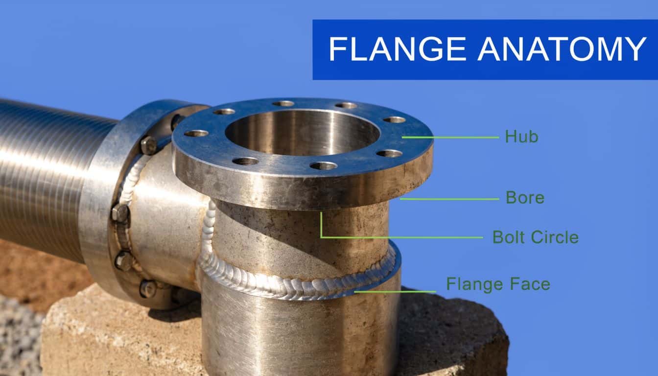
The four parts that matter
Start with the flange face. This is the sealing surface against the gasket and mating flange. In UK hydraulic assemblies, raised face is common because it is available, familiar to fitters, and practical for general industrial duty. RTJ faces sit higher up the severity scale, but only make sense when the mating components, bolting practice, and inspection regime are set up for them. A damaged or poorly finished face will defeat a good design very quickly.
The flange body carries the bolt load and has to hold its shape under assembly load and service load. If it distorts, gasket compression becomes uneven and minor weeps start to appear, especially after temperature change or a shutdown and restart.
The tapered hub is the defining feature. It gives the pipe-to-flange transition a gradual change in section, which lowers local stress at the weld area compared with cruder geometries. That matters on hydraulic power units, mobile plant, and test circuits where the line sees frequent pressure pulses rather than a steady, gentle duty.
Then there is the bore and neck preparation. The bore should suit the pipe or tube wall so the internal profile stays as clean as possible through the joint. In practice, that means checking more than nominal size. Schedule, wall thickness, and connection standard all need to line up, especially on mixed-spec equipment where BSP, metric, and flange interfaces meet. MA Hydraulics deals with that problem regularly when customers are also sorting thread conversions such as BSP to metric hydraulic adaptors.
Why the geometry works
A weld neck flange performs well because the load path is controlled. Bolt load, pipe stress, and pressure-induced force do not all change direction at one abrupt shoulder. They pass through a section that has been shaped for that job.
That does not make it automatically right for every line.
The trade-off is fabrication quality. A weld neck flange gives better mechanical behaviour in service, but only if fit-up, bore match, weld prep, and alignment are right. Poor hi-lo at the bore, excess weld reinforcement, or a neck forced into position during tack-up will put stress back into the very area the design is meant to protect.
For hydraulic work, that smooth bore transition has another benefit. It reduces local disruption to flow at the joint. The gain is usually not dramatic in a short line, but on contaminated service, high-cycle systems, or circuits where valves and manifolds already generate turbulence, every poor internal transition adds another wear point.
What works in practice
Three advantages show up repeatedly in the field:
- Lower stress concentration at the weld zone. The taper reduces the abrupt change between pipe and flange body.
- Better internal alignment. A correctly matched bore gives a cleaner flow path and avoids an internal lip.
- Stronger inspection potential. The butt weld is better suited to the weld quality control expected on higher-consequence hydraulic pipework.
At MA Hydraulics, the failures that cause the most trouble are rarely dramatic burst events. More often, they start as a slight leak after vibration, a gasket that needs repeated retightening, or a weld area that has been carrying misalignment for months. The flange type, the welding standard, and the assembly discipline all show up in those outcomes.
A weld neck flange gives you margin in service. It does not forgive poor preparation.
Raised face and RTJ in real service
Raised face is usually the practical choice for general hydraulic systems because mating parts, gaskets, and replacement stock are easier to source across UK industrial maintenance channels. RTJ comes into play where sealing security and pressure class justify the added control over machining, gasket selection, and assembly practice.
Design engineers should also look past the catalogue sketch. Bore, hub profile, flange facing, bolt circle, and material condition affect whether the joint will behave properly once welded into a live hydraulic system. If a special bore, non-standard thickness, or close-tolerance mating face is needed, machining quality matters as much as flange style, which is why manufacturers often rely on advanced machining techniques for tight-tolerance components and repeatable fit.
The short version is simple. A weld neck flange is not just a stronger-looking flange. It is a geometry choice that improves load transfer, supports weld integrity, and gives a better chance of long-term sealing in hard-worked hydraulic service.
Navigating Flange Standards and Material Specifications
A maintenance shutdown in the UK can lose half a shift before the first bolt is tightened if the flange on the bench is ASME, the mating item is EN, and the paperwork only says "weld neck, 2 inch". That is a specification problem, not a fitting problem. In hydraulic service, it usually shows up later as delay, rework, or a joint that should never have been assembled.
ASME and BS EN in UK hydraulic work
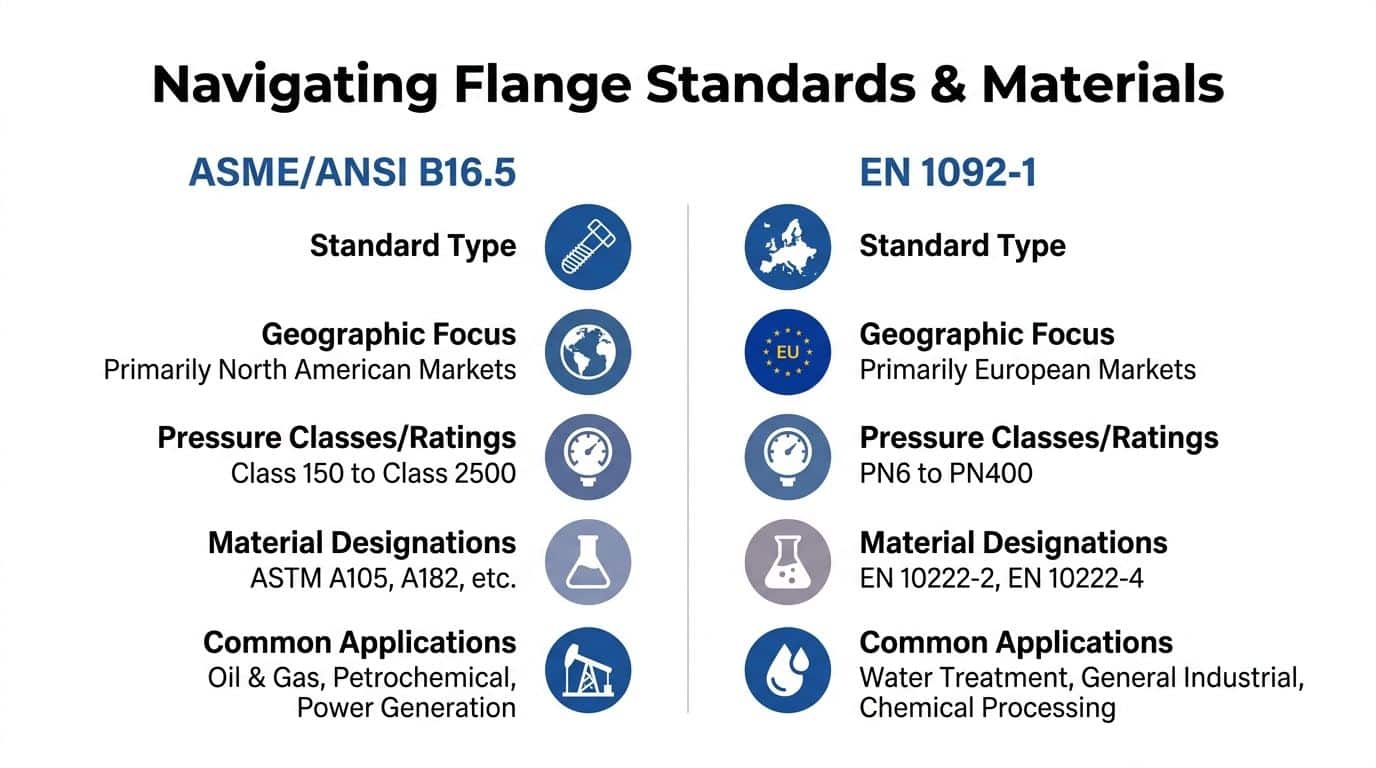
In UK industrial and mobile hydraulics, the two standards families seen most often are BS EN 1092-1:2018 and ASME B16.5. Both are well established. They are not drop-in equivalents.
At MA Hydraulics, specification discipline is paramount. A plant may have European process pipework, an American-origin power unit, and a legacy machine modified years ago with whatever was available during a breakdown. On paper, the flanges can look close. On the bench, bolt circle, facing details, thickness, pressure designation, and certification route decide whether the joint is correct.
Check these points before ordering or welding anything in:
- Pressure designation. Confirm whether the mating parts are class-based or PN-rated
- Facing type. Raised face and RTJ are not interchangeable choices
- Bolt pattern and flange thickness. Similar dimensions are not enough
- Material grade and test certification. Match the project requirement, not just the stock code
- Marking and traceability. Required for many site QA systems and regulated installations
That last point gets missed too often. If the flange cannot be traced properly, a lot of UK sites will not accept it into a pressure-containing assembly, even if the dimensions are right.
Where DIN still appears
DIN-pattern flanges still turn up in older presses, imported hydraulic packs, quarry and agricultural equipment, and plant that has been repaired over many years. The practical issue is compatibility.
A mixed-standard joint often looks "near enough" during a shutdown. That is how teams end up slotting holes, forcing bolt-up, or accepting poor gasket contact to get production back. Those choices store up the next failure. The better approach is to identify the governing standard, replace like-for-like where needed, or redesign the connection properly if the system is being converted.
Material selection follows service conditions
Material choice should come from the fluid, the environment, the temperature range, and the maintenance reality on site. There is no default material that suits every hydraulic duty.
| Material route | Typical use in UK hydraulic service | Main trade-off |
|---|---|---|
| Carbon steel such as ASTM A105 | General industrial hydraulic systems in controlled environments | Good availability, but corrosion protection matters |
| Stainless grades such as ASTM A182 F304/F316 | Washdown areas, coastal sites, corrosive atmospheres, cleaner duties | Higher cost and longer lead times on some sizes |
| Higher-alloy or special materials | Aggressive media, severe environments, project-specific compliance demands | Tighter procurement control and higher manufacturing cost |
A105 is common for good reason. It is widely available, practical for mainstream hydraulic work, and usually the most economical route. It stops being the right answer when external corrosion, contaminated environments, or fluid compatibility start driving the failure mode.
For special bores, close-tolerance faces, or non-standard transitions, machining quality matters as much as the material itself. Poor geometry can undo a good material choice. If you need a manufacturing reference point for precision work on specialist parts, this overview of advanced machining techniques is useful background.
A separate source of confusion sits between threaded adaptors and flanged connections, especially on mixed-standard systems. Engineers checking interfaces often use size references such as this guide to 1/4 BSP and metric threads to avoid specifying the correct flange against the wrong upstream fitting.
Workshop rule: do not approve a weld neck flange by size and name alone. Approve the standard, pressure designation, facing, material grade, certification, and mating details as one package.
Understanding Dimensions and Pressure-Temperature Ratings
A flange that looks right on the bench can still be wrong in service. In UK hydraulic systems, especially on power packs, presses, mobile plant, and coastal or dirty industrial sites, sizing errors usually show up later as leakage, bolt loosening, turbulence at the bore, or a joint that never quite settles after commissioning.
The dimensions that decide fit
Start with nominal size, then keep going. NPS tells you the flange family. It does not confirm that the part will match the pipe, the weld prep, the mating flange, or the bolt set being used on the job.
The dimensions that need checking are straightforward, but they must be checked together. Outside diameter, flange thickness, bolt hole quantity and size, pitch circle diameter, hub geometry, raised face details, and bore all affect whether the joint will assemble properly and carry load as intended.
The bore deserves extra attention. A weld neck flange should be bored to suit the pipe wall and internal flow path, not just the nominal line size stamped on the drawing. If the flange bore leaves a step into the pipe, the result is a local restriction. On hydraulic return lines that may mean avoidable pressure loss. On pressure lines with pulsation, it can add turbulence and stress concentration where the system already has enough of both.
In practice, MA Hydraulics sees this most often on replacement work. A maintenance team orders by nominal size and pressure class, then finds the new flange does not match the existing schedule or wall thickness. The bolt pattern may fit, but the bore transition is poor. That is not a paperwork problem. It is a service-life problem.
Reading the pressure class properly
Pressure class has to be read against temperature and material. A Class 300 marking is not a blanket permission to run that flange at one pressure under all conditions.
As metal temperature rises, allowable pressure falls. That matters in hydraulic systems more often than some designers expect. Oil heating during prolonged duty, hot washdown environments, poor cooling, and radiant heat near engines or process equipment can shift the actual flange temperature well above the ambient figure used during early design.
Material matters as well. The rating table you check must match the flange material and the applicable standard. If the material, facing, or standard changes, the allowable conditions may change with it.
The practical sequence is simple. Define the operating envelope first, including start-up, overload, pressure spikes, and expected oil temperature. Then confirm that the flange class still covers that duty. If you need to sense-check the hydraulic side before fixing the joint specification, this guide on how hydraulic pressure is calculated is a useful reference.
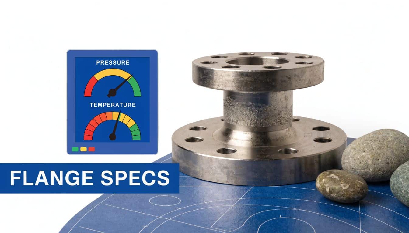
A visual look at flange sizing and ratings
The relationship between dimensions, pressure class, and service conditions is easier to see when the geometry is in front of you.
What the numbers mean on site
Higher pressure classes usually bring thicker sections, more bolt load capacity, and a heavier joint. They also bring trade-offs. Parts cost more, handling is less forgiving, alignment matters more during fit-up, and bolt-up errors become expensive quickly.
That trade-off is normal. The mistake is assuming a familiar class from older plant will still suit a modified duty.
For UK industrial and mobile hydraulics, the safe approach is to treat dimensions and ratings as one check, not two separate boxes. A flange must fit correctly, weld correctly, and retain margin at the actual service temperature. That is the standard we apply when supplying weld neck flanges and related hydraulic components at MA Hydraulics, because a joint that only works on paper is not fit for service.
Selection Criteria for Hydraulic and Industrial Applications
Selecting welding neck flanges properly means resisting the urge to reduce the decision to size plus pressure class. That’s a start, not a finished specification.
The correct question is this. What will the joint experience in service, and what evidence do you have that the chosen flange, weld, bolting, and inspection route can handle it?

The selection checks that matter
A sound selection process usually includes the following:
- Pressure and temperature together. Don’t approve a flange on pressure alone. Check the actual operating envelope, including abnormal conditions and warm-up states.
- Fluid character. Clean mineral hydraulic oil is one thing. Aggressive or contaminated media can change the material decision quickly.
- Vibration level. Mobile plant, tractors, and machinery with repeated shock loading demand far more from the joint than static indoor pipework.
- Duty cycle. A line that sees repeated starts, stops, and pressure pulses should be treated as a fatigue problem, not just a containment problem.
- Inspection route. If the service is critical, think ahead about NDT, documentation, and how the weld will be accepted.
Some of these are design-office decisions. Others only become obvious when you’ve watched machines fail in the field. Both perspectives matter.
UK compliance is part of selection
In the UK, flange selection is not only an engineering judgement. It is also a compliance decision where the system falls within regulated pressure equipment and pressure systems duties.
For OEMs and MRO teams, one of the key challenges is meeting Pressure Equipment Directive 2014/68/EU requirements as enforced via UKCA marking for bespoke power packs and related hydraulic assemblies. In the same UK-specific discussion, HSE data from 2025 reports that 17% of hydraulic failures in North Lincolnshire industries were linked to non-compliant flanged joints under high vibration, which is why suitable NDT protocols, including radiographic testing equivalent to BS EN ISO 5817 for butt welds, matter in hydraulic contexts, as noted in this review of weld neck flange compliance gaps.
That should change how you select the component. If a joint needs a butt weld that can stand up to scrutiny, a welding neck flange starts to make sense for reasons beyond pure pressure capacity. It gives you a joint form that is structurally more appropriate for severe service and more defensible from an inspection standpoint.
If the application could injure someone, damage expensive equipment, or trigger a compliance issue, “close enough” is not a selection method.
What tends to work and what doesn’t
What works is a selection note that records the actual service conditions, identifies the standard, confirms the material, and specifies the inspection and certification route. That gives procurement, fabrication, and maintenance the same target.
What doesn’t work is treating the flange as a commodity item while everyone assumes someone else has checked the details. That’s how mixed standards, poor material choices, and avoidable fit-up problems get into the build.
A welding neck flange isn’t mandatory for every hydraulic line. But where pressure, vibration, fatigue, and regulatory exposure all sit in the same job, it is usually the safer and more professional choice.
Best Practices for Welding Installation and Maintenance
A well-selected flange can still fail early if the installation is careless. Most of the avoidable problems show up in three places. Poor fit-up before welding, poor bolt loading during assembly, and poor corrosion control once the machine goes back into service.
Fit-up and weld preparation
The best welding neck flange in the stores won’t compensate for bad alignment. The pipe has to meet the neck properly, the bevel needs to be clean and appropriate for the procedure, and the root has to be prepared so the butt weld is sound through the section.
Before striking an arc, check these points:
- Alignment first. Pulling pipe into place with studs is bad practice. The flange should sit naturally in line with the mating connection.
- Clean prep. Remove contamination, paint, scale, and oil from the weld zone and sealing areas.
- Correct bore match. Confirm the flange bore suits the pipe schedule so you’re not building in an internal mismatch.
- Face protection. Keep the raised face or sealing area protected while welding and handling.
A skilled welder will usually favour a controlled root pass and then build the joint with a procedure suited to the material and wall thickness. The exact process choice depends on the job and approved welding practice, but the principle doesn’t change. Sound prep beats heroic welding every time.
Bolting and assembly discipline
Once the weld is accepted and the flange faces are ready, bolting needs the same level of care. Uneven tightening distorts load across the joint and can damage the gasket before the system is even pressurised.
A practical assembly routine looks like this:
- Inspect the face and gasket for marks, contamination, or the wrong sealing type.
- Lubricate and check studs and nuts if that suits the procedure being used.
- Tighten in a star pattern so load comes on evenly.
- Bring torque up in stages rather than in one pass.
- Recheck after settlement if the assembly method calls for it.
The leak you see at commissioning often started as a fit-up or bolting error made hours earlier.
Corrosion is the UK problem many teams underestimate
Hydraulic engineers tend to focus on pressure, and rightly so. But on mobile plant and outdoor equipment, external corrosion can cut service life faster than many expect.
UK-specific discussion of weld neck flange maintenance notes that 28% of hydraulic flange failures in agricultural machinery in North Lincolnshire stemmed from external corrosion, and that even though weld neck flanges are the stronger option, their lifecycle in corrosive agri and marine environments is shortened without preventative coatings or more suitable alloy selection. That point is raised in this article on weld neck flange maintenance questions.
That lines up with what maintenance teams see in the field. The failure often doesn’t begin at the sealing face. It begins on exposed external surfaces where moisture, fertiliser residue, washdown, and trapped debris attack the component over time.
For teams reviewing coating strategy, this guide on how to protect metal from rust is a useful companion read because it helps frame the preventative side, not just the repair side.
A maintenance routine that holds up
For ongoing service, keep the routine simple and repeatable:
- Look for coating breakdown around the hub, bolt area, and flange perimeter
- Check for staining or weeping that may indicate early leakage
- Inspect after vibration events or any mechanical strike to connected pipework
- Record wall loss or visible degradation rather than relying on memory
- Escalate repairs properly if corrosion affects thickness, weld integrity, or pressure containment
What doesn’t work is cleaning and repainting over a problem without understanding whether the base metal is still acceptable. In a regulated environment, that can move a maintenance issue into a compliance issue very quickly.
Procuring Flanges and Getting Expert Hydraulic Support
Buying welding neck flanges well means buying more than a nominal size. The procurement decision has to lock together the standard, class or pressure designation, face type, material, certification requirements, and the actual service conditions the joint will see. If one of those is left vague, the risk usually turns up later in fabrication or commissioning.
That’s why experienced buyers ask better questions than “Have you got one in stock?” They ask whether the bore suits the pipe schedule, whether the flange matches the mating standard, whether the material paperwork is available, and whether the intended duty makes the chosen type sensible in the first place.
For hydraulic projects, that technical check matters just as much as lead time. A flange that arrives quickly but creates a mismatch in the workshop is not the right part. A component that fits the drawing but doesn’t fit the compliance route isn’t the right part either.
If you’re procuring flanges as part of a wider hydraulic build, it also helps to deal with a supplier that understands the system around the component, not just the component itself. That’s particularly useful when the flange sits within a broader package of valves, manifolds, pumps, pipework, or a complete power unit. For broader component sourcing and system support, MA Hydraulics also provides hydraulic equipment supply.
The main point is simple. Welding neck flanges are rarely the place to cut corners. When selected and installed properly, they repay the extra care through better reliability, cleaner inspection outcomes, and fewer repeat failures. In hydraulic systems, that’s usually the difference between a connection that disappears into the background and one that keeps dragging the job backwards.
If you need help selecting the right welding neck flange, material, or pressure class for your hydraulic system, speak to MA Hydraulics Ltd. For the correct component selection for performance and safety, phone 01724 279508 today or send your requirements through the contact page.
