
A hydraulic power pack rarely fails in a neat, convenient way. The alarm sounds on a night shift, the operator hears a change in tone, and by the time maintenance reaches the plant floor the visible damage already looks obvious. The trap is to treat that obvious damage as the whole story, because the component that stopped working is often only the last thing in a longer failure chain.
That's why failure root cause analysis matters on real UK factory floors. A seized pump, a sticking valve spool, or a drifting cylinder can be the symptom, while the fault sits upstream in contamination control, installation practice, maintenance scheduling, or even the specification chosen at commissioning. The British safety view is clear on this point, HSE guidance pushes investigators towards the underlying or latent causes, because that's what stops recurrence, not blame or a quick replacement of the visible part (HSE guidance on investigation and root causes).
Why Most Hydraulic Failure Investigations Miss the Real Problem
The call comes in at 02:10 from a Midlands pressing plant. A gear pump on a hydraulic power pack has seized, the line has stopped, and the night shift has already moved into damage-control mode. Someone swaps the pump, tops up the reservoir, bleeds the air out, and gets the machine running again, only for the replacement unit to fail within 72 hours.
That pattern is painfully familiar. The failed pump is real evidence, but it isn't the root cause by itself. If the team stops at the component level, the same contamination ingress, suction restriction, fluid mismatch, or thermal stress will just attack the next pump, valve, or seal in line.
The visible failure is rarely the whole failure
A hydraulic fault looks mechanical because the final event is mechanical. A seized shaft, scored gear teeth, or a burnt solenoid coil is the thing everyone can see, touch, and replace. But in UK industrial systems, the deeper fault often sits in the background, a breather that lets in dirt, a suction strainer that's been left too long, a fluid grade that can't cope with cold starts, or a maintenance regime that only reacts after breakdown.
Practical rule: treat the failed part as a witness, not the culprit.
That mindset change is the heart of proper failure root cause analysis. HSE's investigation approach is built around finding the underlying cause, then converting that finding into risk controls and an action plan, not just a repair ticket (HSE investigation workflow). For hydraulics, that means asking why the component failed in the first place, then asking why the system allowed that condition to develop.
The systemic causes that keep repeating
In practice, the repeat offenders are predictable. Contamination ingress scores high because one dirty fill, one poor breather, or one bypassing filter can damage multiple components over time. Thermal cycling matters just as much, because hot oil and cold starts change viscosity, clearances, and seal behaviour. Specification mismatches are another quiet killer, especially when the pump, valve, or hose was chosen for nominal conditions that don't match the duty cycle.
There's also the maintenance side. If inspection routines don't catch early wear, if records are incomplete, or if production pressure pushes teams to defer planned work, the system becomes more vulnerable with every shift. That's why the rest of this guide stays focused on what works on factory floors, tracing faults back through evidence, test results, and operating history until the source becomes visible.
Securing the Scene and Collecting Evidence
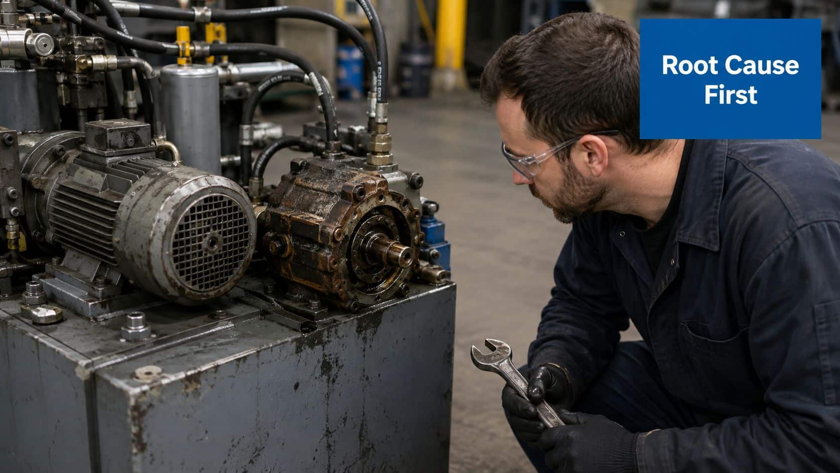
The first hour after a hydraulic failure decides how good the investigation will be. If the team rushes straight to strip-down, the most useful evidence disappears with the oil, the grime, and the first wipe of a rag. HSE's accident-investigation model starts with gathering information before analysis, and that's exactly the right sequence for hydraulic work too (HSE 4-step investigation workflow).
First 60 minutes checklist
- Isolate the machine safely. Lock out the electrical supply, relieve stored energy, and make sure accumulators are depressurised before anyone reaches for tools.
- Contain the spill. Use drip trays, absorbents, and a proper clean-up process so the failure site stays readable and the floor stays safe.
- Photograph everything in place. Capture the pump, hoses, valve blocks, gauges, and any visible leaks before a single component is removed.
- Record live readings. Save pressure, temperature, and any PLC or HMI alarm data while it's still available.
- Tag removed parts. Bag and label pumps, valve spools, cylinder seals, and suspect filters so wear patterns and contamination traces are preserved.
- Talk to the operator. Ask what changed, noisy running, cycle-time drift, temperature rise, sluggish movement, or pressure fluctuation, and write it down immediately.
The clean-up discipline matters because a washed component is no longer the same evidence. A scored spool, a coked seal, or a dirty suction strainer can tell a very different story before it's scrubbed, blasted, or left to drain on a bench. The most common mistake I see is a well-meaning fitter cleaning parts before inspection, then wondering why the failure never makes sense.
What to capture and how to store it
Oil samples need to come from the right places, not just the reservoir. Pull from the reservoir, the pump inlet, and the return line using clean sampling bottles that match the sample-handling discipline used by the plant. Keep chain-of-custody notes, because once a sample gets mixed up, the contamination result is far less useful.
Write the timeline before the repair starts.
Retrieve the maintenance history from the CMMS, note any recent fluid top-ups, filter changes, or recurring alarms, and save the exact timestamp of every photo and reading. If the site uses thermal checks during fault-finding, the same evidence pack can be cross-referenced with the inspection approach at MA Hydraulics thermal imaging inspection. The goal is simple, build a file that lets you test a hypothesis later instead of guessing under pressure.
Choosing the Right RCA Method for Your Failure
Not every fault needs the same investigation depth. A single dead solenoid coil doesn't need the same treatment as a recurring pressure-control issue that knocks out a whole production line. The HSE and UK public-sector guidance both point towards structured methods such as the 5 Whys when the causal chain is short, but more complex systems need a broader lens (HSE human factors investigation guidance).
Picking the method that fits the fault
Use 5 Whys when the failure is clear, isolated, and the chain is likely short. A solenoid valve coil burnout, for example, can often be traced through power supply, duty cycle, and overheating without needing a large team. The output is usually a short cause chain, a clear action list, and a tight corrective note for maintenance records.
Use a Fishbone diagram when several variables could be pulling the fault in different directions. Recurring proportional valve spool sticking is a good example because contamination, oil chemistry, electrical signal quality, and mechanical wear can all interact. A fishbone works well because it stops the team from locking onto the loudest explanation too early.
Use Fault Tree Analysis for safety-critical circuits. If a counterbalance valve failed to hold a load, you need logic that maps component failures, human actions, and conditional combinations, not just a list of guesses. That structure is useful when the consequence is serious and the investigation must show how different faults combined.
Use FMEA before commissioning or redesign. It's the right choice when you're assessing a hydraulic power pack, manifold, or new duty cycle and want to identify weak points before the machine enters service. That makes it a design-control tool as much as an investigation method.
| RCA Method Selection Matrix for Hydraulic Failures | Best For | Typical Duration | Team Size | Hydraulic Example |
|---|---|---|---|---|
| 5 Whys | Straightforward single-component faults | Short | Small | Solenoid valve coil burnout |
| Fishbone Diagram | Multi-variable recurring faults | Moderate | Small to medium | Proportional valve spool sticking |
| Fault Tree Analysis | Safety-critical circuits | Moderate to long | Medium | Counterbalance valve not holding a load |
| FMEA | Pre-commissioning and design review | Longer | Medium to large | New hydraulic power pack design |
A useful decision rule is severity first, then recurrence, then system criticality. If the machine failed once and the evidence is clean, a simple method is often enough. If the same symptom keeps coming back, or the failure could create a load-drop or safety event, use the more structured method and involve more than one discipline in the review.
Testing and Verifying Suspected Root Causes
A hypothesis isn't a conclusion until the test data backs it up. Too many investigations drift into expensive part swapping because the team finds a likely fault, then treats likelihood as proof. That shortcut wastes time and often hides the system interaction underneath.
Prove the fault on the bench or in situ
For a gear pump, start with volumetric efficiency checks, case drain flow, and shaft seal inspection. Those tests help separate internal wear from cavitation damage, because a pump can look equally rough on the outside while failing for very different reasons inside. Use flow measurement, pressure transducers, and visual inspection together rather than leaning on one clue.
For a directional control valve, check spool leakage, solenoid current draw, and pilot pressure. That combination helps distinguish an electrical supply issue from contamination-induced sticking or a pilot problem. If the solenoid is drawing the expected current but the spool is still slow to shift, contamination or mechanical drag moves higher on the list.
For an actuator, carry out load-holding tests, seal bypass checks, and rod-surface inspection. Drift doesn't always mean worn seals, and a cylinder can be blamed too quickly when the true restriction sits elsewhere in the circuit. If the rod is clean and the bypass is low, look back at the load path, not just the cylinder.
Practical rule: test the whole chain, not just the dead part.
Reference points that separate cause from symptom
A clean-looking component can still be the victim of a system fault. Relief valve chatter, for instance, can damage a pump downstream even when the pump itself is the part that finally fails. That's why the evidence pack from the scene matters, because test results are only meaningful when they're tied back to operating pressure, fluid condition, and fault history.
The same logic applies to oil condition work. If you're already reviewing contamination behaviour, the guidance at MA Hydraulics oil analysis is a useful companion to bench testing because fluid data often confirms whether the failure came from wear, ingress, or poor housekeeping. In practice, the best teams use test data to eliminate suspects, not just to confirm the favourite theory.
| Hydraulic Component Testing Quick Reference | Test Procedure | Instrument Required | Pass/Fail Threshold |
|---|---|---|---|
| Gear pump | Volumetric efficiency and case drain flow | Flow meter, pressure transducer | Output and leakage must align with expected service condition |
| Directional valve | Spool leakage and solenoid current draw | Multimeter, pressure gauge | Current and movement must both be normal |
| Actuator | Load-holding and seal bypass check | Pressure transducer, flow meter | Load must hold and bypass must stay within expected limits |
| System circuit | Pressure stability under load | Pressure transducer, data log | Pressure must remain stable without chatter or collapse |
The point of testing is not to prove the component is bad. It's to prove why it went bad, and whether the same condition still exists elsewhere in the system.
Real Hydraulic Failure Case Studies and Lessons Learned
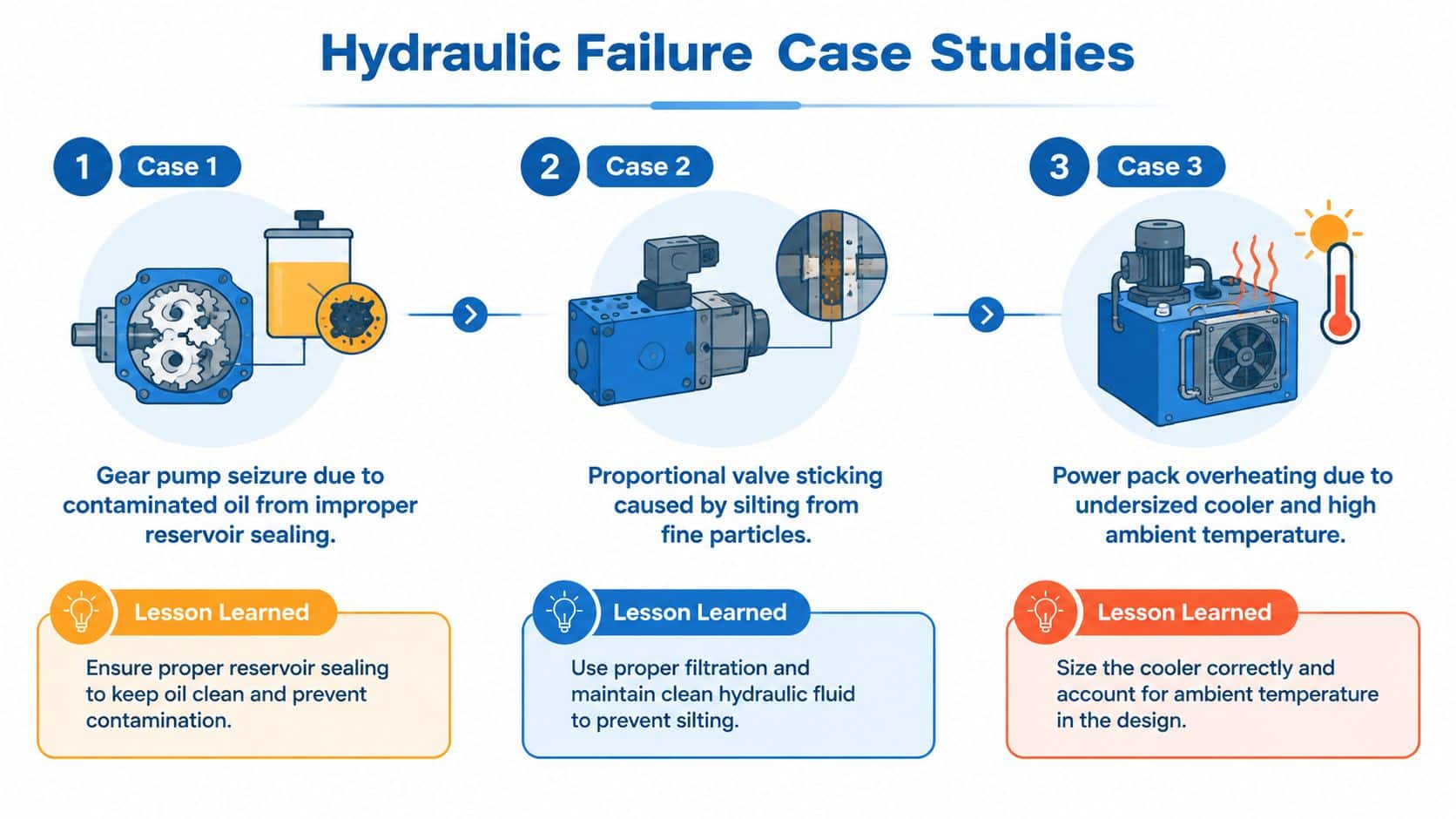
Three recurring patterns turn up again and again in plant work. The symptom is always obvious, but the cause sits a layer deeper, sometimes in a small detail that no one checked because the failure looked too simple to justify a full investigation.
Case one gear pump seizure that kept coming back
A steelworks power pack kept eating gear pumps. The first assumption was normal wear, then bad luck, then a weak replacement unit. Once the failed pumps were opened up, the evidence pointed elsewhere, the oil was dirty, the offline filter was no longer doing its job properly, and the bypass setting had been adjusted incorrectly, allowing unfiltered oil into the system during cold starts.
The useful lesson wasn't “replace the pump more carefully”. It was that the filter strategy had failed before the pump did. The corrective action had to focus on filtration, bypass control, and start-up conditions, not just stocking a spare pump. Once the system issue was addressed, the recurring seizure pattern stopped looking mysterious.
Case two actuator drift on a mobile platform
A mobile machine came in with intermittent drift on one actuator. The first repair was the obvious one, replace the cylinder seals. The drift came back, which meant the seal was never the true root cause, only the component that showed the symptom.
Further checking showed a subtle restriction in the load-sensing signal line. That restriction caused the counterbalance valve to open partially, so the actuator couldn't hold position consistently under load. The fault sat in the control signal path, not in the cylinder itself, which is exactly why symptom-led repairs keep failing on mobile kit.
Case three repeating proportional valve failure
A proportional valve assembly failed three times in the same installation. Each replacement seemed fine at first, then the coil overheated and the spool response became poor again. The issue was voltage drop across undersized cabling, which starved the solenoid and caused partial spool shifts that generated excess heat.
That one is a classic commissioning miss. The valve looked like the obvious victim, but the circuit was under-supplied electrically. Once the cabling was corrected and the supply path checked properly, the repeat failures stopped. For a deeper process view of how these faults can be turned into sustainable fixes, there's a useful reference in Wisely process improvement services, especially where investigation findings need to be folded into wider maintenance discipline.
Turning Findings into Corrective and Preventive Actions
A root cause report that sits in a folder changes nothing. The investigation only pays off when the findings become physical changes, maintenance changes, or specification changes that stop the failure from repeating. The Civil Aviation Authority is blunt on this point, poor-quality root cause responses can contribute to repeat or similar non-conformances, and the same reality shows up in hydraulic maintenance every week (CAA root cause analysis guidance).
Corrective action first, preventive action second
A corrective action fixes the verified cause on the failed machine. If contamination caused the failure, that might mean replacing damaged parts, cleaning the circuit, correcting filtration, and restoring the system to a known baseline. If the issue was a specification mismatch, the correction could involve component replacement with parts that match the operating duty.
A preventive action stops the same pattern from appearing elsewhere. That usually means updating maintenance routines, changing inspection intervals, improving fluid sampling discipline, or revising design standards for similar machines. In other words, one action repairs the machine, the other repairs the system that allowed the problem to exist.
What to change when contamination or mismatch is the cause
For contamination-related faults, tighten filtration requirements and define oil cleanliness targets that the maintenance team can verify. Put fluid sampling on a condition-based schedule instead of relying on a fixed guess, then feed the results into planned maintenance rather than waiting for failure. If a pattern shows up across machines, the issue may not be the component at all, but the plant's contamination governance.
For specification problems, compare component ratings against the pressures, temperatures, and duty cycle seen on site. If the machine is running outside the assumptions used at purchase, the original design may never have had enough margin. That's the point where a redesign conversation becomes necessary, either with the OEM or with a hydraulic specialist who can re-evaluate the circuit.
If you're formalising the response, MA Hydraulics Ltd can fit into that process as one option for component selection, troubleshooting, and power-pack support when the root cause points to a deeper system issue.
Keep the action log boring and disciplined. Name an owner, set a date, and verify the result.
The organisations that do this well don't just list fixes. They rank actions by risk and effort, then they close the highest-risk gaps first. That is what stops the report from becoming a monument to good intentions.
Templates Checklists and Getting Expert Support
The fastest way to make failure root cause analysis repeatable is to standardise the paperwork around it. A good investigation pack needs a report template, an evidence checklist, and an action tracker that everyone on the shift can use without improvising. The structure matters because later reviews are only as good as the notes taken at the time.
Three templates worth keeping ready
- Failure investigation report template: include failure date and shift, equipment ID, operator name, operating condition at failure, visible symptom, suspected cause, 5 Whys notes, fishbone categories, contamination analysis result, test readings, root cause decision, and sign-off chain.
- Post-failure evidence checklist: list fluid samples from each relevant point, pressure readings, temperature logs, component photographs, tag numbers for removed parts, and the location where each item is stored.
- Corrective action tracking sheet: record the action description, risk level, owner, target date, verification method, close-out evidence, and management sign-off.
The best templates also force consistency in the details that get forgotten under pressure. If the same form captures the machine state, the operating load, and the contamination result every time, pattern recognition becomes much easier across shifts and sites. A simple link to a preventive routine, such as the one at MA Hydraulics preventive maintenance checklist, helps turn one-off learning into a standard habit.
When to bring in outside hydraulic support
Some problems are bigger than an in-house strip-and-repair job. Intermittent faults that disappear when the machine stops, warranty disputes with a supplier, and contamination events affecting multiple machines all justify specialist help. That's especially true when you need component-level testing, particle counting, or a second opinion before committing to major replacement work.
If the failure keeps returning, don't let the investigation stall at the last broken part. Phone 01724 279508 today, or send us a message through MA Hydraulics Ltd. MA Hydraulics Ltd supports UK industrial and mobile hydraulic work with diagnostic testing, repair support, and component-level failure analysis that can get stubborn faults back under control.
