
The most common advice about a 15mm solenoid valve is also the most misleading: match the valve to the pipe and check the coil voltage. That can get the connection wrong, the flow wrong or the water approval wrong, because “15mm” might describe the pipe connection, the solenoid operator or the valve's internal orifice.
For a reliable selection, treat the label as a starting point, not a specification. Record the actual connection, flow requirement, operating limits, fluid compatibility and compliance needs before ordering.
15mm Solenoid Valve Specifications and What 15mm Means
“15mm” can identify three different dimensions: the pipe connection, the solenoid operator or the valve's internal port. The distinction matters because a matching connection does not establish the valve's flow capacity or confirm that its operator fits the intended assembly.
The table separates the reference dimensions and ratings. Figures apply to the named configurations, not automatically to a complete machine or installation. UK copper-pipe sizing is described in the UK copper-pipe sizing guide; the Parker and WRAS values are product-specific data from the Parker Viking Xtreme catalogue and the WRAS approvals directory.
| Parameter | Reference value | What to check |
|---|---|---|
| Solenoid operator size | 15 mm | Describes the coil body, not the flow path |
| Pipe connection | 15 mm copper outside diameter | Confirm the fitting type matches the tube |
| Thread | G 1/2 BSP parallel thread is one specified example | Confirm the thread standard and sealing method |
| Coil voltage | 24 V DC on the Parker Viking Xtreme configuration | Match the PLC or control output |
| Electrical interface | EN 175301-803 Form C (ISO 15217) | Check pin spacing and mating plug |
| Maximum working pressure | 10 bar on the Parker configuration; 9.80665 bar on the WRAS normally closed metal range | Compare the component rating with the duty; for potable duty, use the lower listed rating when comparing these products |
| Operating temperature | -10 to +50 °C on the Parker configuration; up to 85 °C on the WRAS range | Check the operating range against fluid and ambient temperatures |
| Ingress protection | IP65 on the Parker Viking Xtreme configuration | Assess protection for the complete installation |
| Flow coefficient (Kv) | Typical small-valve range: 0.2–1.0 m³/h at a 1 bar differential pressure | Treat as an indicative range; confirm the selected valve’s rating and flow at its stated pressure differential |
| Body and seal materials | Brass body, stainless steel spring and EPDM seal on the WRAS range | Check wetted materials against the fluid |
Three different meanings of “15mm”
In UK plumbing, 15mm usually refers to copper tube's outside diameter, not its internal bore. The size is common on individual outlets such as taps, basins, radiators, washing machines and dishwashers. Metric 15mm and 22mm tube became established for new work after the UK moved from imperial sizes.
In pneumatic equipment, “15mm” can describe the solenoid operator. The Parker Viking Xtreme example in the table has a 15mm operator, but that measurement does not specify the valve's port size or flow capacity. It identifies an operator dimension, not a hydraulic connection.
The third meaning is the valve's port or orifice size: the internal passage through which fluid flows. It can be smaller than the pipe connection, and the passage geometry also affects flow. Two valves sold as 15mm may therefore have different flow capacities even when they connect to the same pipe.
Record the connection, operator and orifice or Kv as separate specification fields. A 15mm connection indicates compatibility with a common UK pipe size; it does not define a universal flow rate. For selection, compare the required flow with the valve's Kv at the relevant pressure differential, then check that the specified connection and operator match the installation.
Body Materials, Fluid Fit and Plastic Water Valves
A valve that fits a 15mm water line can still be unsuitable for the fluid or operating conditions. The WRAS-listed normally closed metal range described here has a brass body, stainless steel spring and EPDM seal. These are construction details for that range, not a general material specification. EPDM can suit water applications, but may be unsuitable for mineral oil and many hydraulic fluids. Check the body and seal against the fluid, temperature and pressure in the circuit.
For potable installations, the Water Supply (Water Fittings) Regulations 1999 call for dezincification-resistant materials in concealed fittings and backflow-prevention devices. Confirm the requirement for the specific installation in the regulations themselves. A brass body or a “water valve” label alone does not establish suitability.
Plastic-bodied 15mm valves are another option for water control on low-pressure duties. The linked listings give indicative prices of £24.14 including VAT for a plastic water solenoid valve and £38.24 including VAT for a 6-volt latching version. Check the plastic 15mm water valve listing and 6-volt latching valve listing for current prices. Price does not confirm potable-water approval or a suitable temperature rating.
Match the connection and material to the job
| Connection or interface | Typical use | What to confirm |
|---|---|---|
| 15mm compression or push-fit (copper) | Individual outlets such as taps, basins, radiators and washing machines | Tube outside diameter and fitting type match |
| G 1/2 BSP parallel thread | Threaded valve ports in hydraulic and process lines | Manufacturer’s thread standard and seal type |
| EN 175301-803 Form C electrical | Coil connection to the control panel | Pin spacing and mating plug |
| Plastic body, 15mm water valve | Water control on low-pressure duty | Potable approval and temperature rating |
A latching valve holds its state without continuous coil power. On power loss, its position may therefore differ from that of a continuously energised coil. Check that behaviour against the required circuit response.
Specify the connection standard, thread and seal material. If a replacement changes the body or seal, confirm compatibility before treating it as interchangeable.
Matching Flow Demand to a 15mm Branch
A 15mm branch can suit one outlet while the building's distribution main needs larger pipework. Size the valve against the actual draw-off demand, not the label alone. The UK plumbing pipe-size guidance gives these indicative flows and pipe-size considerations for domestic water systems.
| Demand point | Indicative flow | Pipe-size guidance |
|---|---|---|
| Basin tap or WC cistern | About 0.1 litres per second | 15mm branch adequate |
| Kitchen sink | About 0.2 litres per second | 15mm branch usually adequate |
| Bath tap | About 0.3 litres per second | 15mm branch usually adequate; check pressure |
| Two-bathroom distribution | Roughly 0.5 to 0.8 litres per second | 22mm to 28mm distribution typically required |
A branch-level fit does not show that one 15mm valve can serve every outlet, particularly when several draw-offs may run simultaneously.
The valve's Kv and pressure drop determine whether it can deliver the required flow at the available pressure differential. Connection size alone does not establish capacity: two valves with 15mm connections can have different internal ports and flow performance. Compare the valve's actual flow path with the duty, including when assessing full-bore valve options.
To compare demand with the manufacturer's Kv data, record:
- Minimum and peak flow: State both in litres per second.
- Available differential pressure: Give the pressure across the valve under operating conditions, not just upstream supply pressure.
- Simultaneous outlets: Identify which taps or appliances may run together.
- Cycle frequency: Include how often the valve opens and closes during normal operation.
If simultaneous use exceeds the 15mm distribution guidance, flag the branch limitation before selecting the valve. The remedy may be a revised branch or distribution arrangement, rather than a different coil.
Operating Limits and Derating Checks
A published operating window describes what a component is rated for, not what the complete machine is guaranteed to withstand. Leave margin below the limits in the reference table, and check the actual duty with the intended fluid, supply and control arrangement.
Check the installation, not just the catalogue
Use this checklist to identify operating conditions that can reduce usable margin:
- Air quality: Contaminated or wet compressed air can shorten seal life. Check filtration and moisture control against the valve's application.
- Switching rate: Rapid cycling can increase heat and mechanical wear. Compare the expected switching frequency with the manufacturer's duty information.
- Cold conditions: Low temperatures can stiffen seals and slow response. Confirm that the valve's materials and response remain suitable at the lowest expected temperature.
- Cabinet temperature: A hot control cabinet can raise the coil's ambient temperature beyond the surrounding room conditions. Assess heat from nearby equipment as well as the external environment.
- Pilot supply: Confirm whether the valve requires internal or external pilot supply. The wrong arrangement can prevent reliable operation even when the nominal pressure appears suitable.
- Electrical load: Match coil voltage to the PLC output, then check inrush and holding current against the cabinet power supply. Specify the mating plug separately if it isn't supplied.
Form C connector fit also deserves a check before ordering. A 15mm operator doesn't guarantee a particular pin spacing: Parker documentation identifies 8mm and 9.4mm variants in related interface modules. Confirm the exact spacing and plug type for the selected valve rather than ordering by operator size alone.
IP65 can be useful for equipment exposed to washdown, dust or vibration, including agricultural and mobile machinery. It doesn't replace a system-level review of the enclosure, cable gland, EMC and mechanical protection. Those details depend on how the valve is mounted and wired in the machine.
Write the operating window down: Record pressure, temperature, voltage and duty cycle on the order, then check that the planned conditions remain within the product's limits with room to spare.
Potable Water Approval and Backflow Rules
A 15mm valve isn't automatically suitable for drinking water. The WRAS approvals directory identifies approved products and their construction, but approval of one valve doesn't establish adequate backflow protection for the complete installation.
The applicable requirements also depend on where the installation is located. England and Wales are governed by the Water Supply (Water Fittings) Regulations 1999; Scotland and Northern Ireland have separate requirements. The Water Supply (Water Fittings) Regulations 1999 require protection appropriate to the highest applicable fluid category downstream. A valve may be approved as a product and still need a separate backflow-prevention device for the installation. For a practical overview of the risk and protection principles, see this guide to understanding backflow prevention.
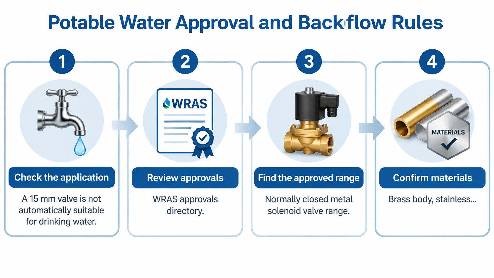
Use this decision path before ordering a valve for potable service:
- Confirm the application. Decide whether the downstream fluid is potable or non-potable. The answer determines which approvals and materials to consider.
- Identify the fluid category and highest downstream risk. Protection must reflect the most significant applicable contamination risk downstream, not just the fluid at the valve inlet.
- Verify the approval. Record the exact approval number and check that its temperature range covers the duty.
- Check material compatibility. Confirm body and seal materials against the fluid and installation conditions.
- Assess backflow protection separately. Establish whether the installation needs an additional prevention device, and select it for the risk.
- Check installation conditions. Confirm valve orientation and the pressure differential required for reliable diaphragm operation.
This process can change the purchase even when a replacement fits the existing pipework. A valve selected by nominal size alone may be unsuitable for the fluid, lack the necessary approval or require a separate backflow arrangement.
Hot-Water Use and Legionella Risk
A 15mm connection does not show whether a solenoid valve will support safe hot-water operation. Its position and behaviour can affect circulation, stagnant pipe sections and the system's hygiene controls.
The HSE says hot-water storage cylinders should store water at 60°C or higher. Its technical guidance also says check valves used to prevent hot-water backflow must be rated for hot-water service, as one side may contact potentially hot water. Read the HSE Legionella guidance alongside the system's temperature and circulation requirements. For a separate perspective on heater service, see water heater repair in San Antonio.
A solenoid valve can create a stagnant section or dead leg, restrict circulation, or fail partly open. A smaller, lower-power valve selected to save water may also restrict flushing, even if its nominal flow appears sufficient. Check the installed arrangement against the circulation and hygiene controls required for the system.
Record these circuit conditions before choosing the valve:
- Water temperature: Include normal operation and the hot-water duty the valve must tolerate.
- Dead-leg length: Identify any stagnant pipe section created by the valve's position.
- Flushing frequency: Define how the circuit will receive adequate flushing during normal use.
- Fail-safe position: State what the valve must do if power is lost or control fails.
- Cleaning access: Confirm maintenance staff can inspect and service the valve and surrounding pipework.
A latching or normally open arrangement may suit a circuit where loss of power or a stuck coil would otherwise leave it in an unsuitable state. The choice depends on the circuit's required behaviour during a fault, not power consumption alone. In commercial premises, plant washdown and process systems, use a hygienically designed control or isolation arrangement if a solenoid would undermine circulation or complicate backflow protection.
Pre-Order Record Checklist
“15mm solenoid valve” is not a complete order description. The label may refer to the pipe connection, while the valve's flow capacity and electrical operator have separate requirements. Record the details below so the selected component can be checked against the actual duty.
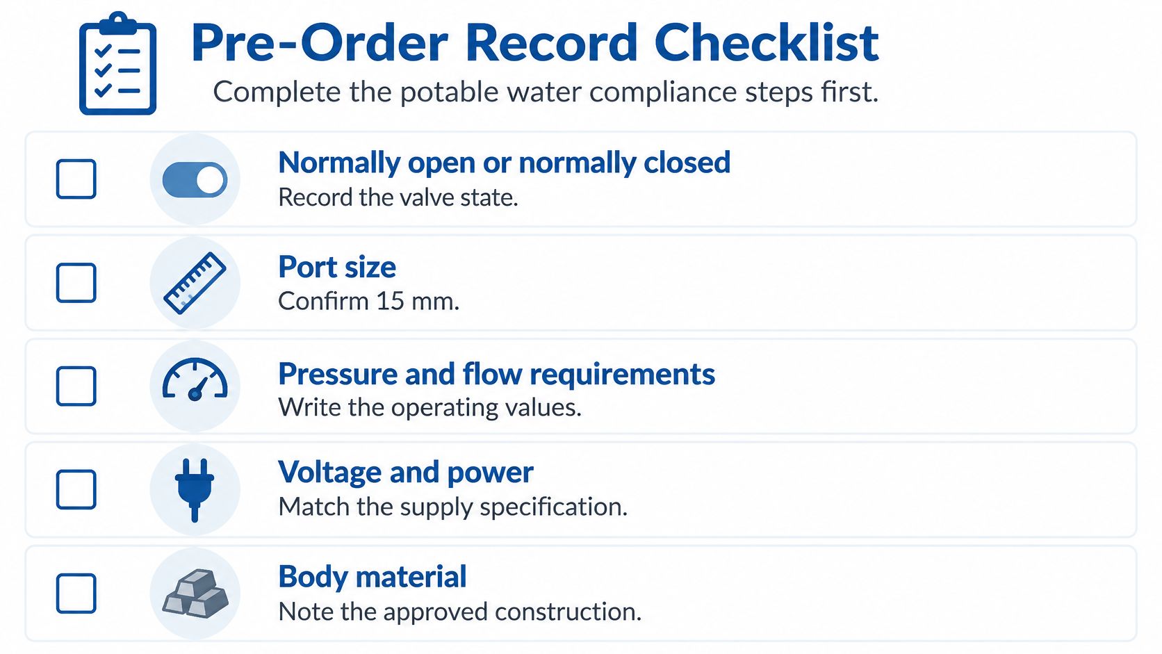
- Normal state and power-failure position: Specify normally open or normally closed, and record what the circuit must do if power is lost. Check that the default behaviour suits the application.
- Coil voltage, duty cycle and control signal: State the controller or PLC output and expected energisation pattern. A matching nominal voltage alone does not confirm that the electrical load is suitable. Compare these requirements with the coil voltage, duty cycle and plug details on the manufacturer's datasheet before ordering. For reference, 24V solenoid valve information can help identify the electrical details to check.
- Connection standard, thread and tube size: Use the manufacturer's stated connection and thread. Do not assume all valves described as 15mm share the same fitting.
- Electrical plug and pin spacing: Record the plug type and interface dimensions. Include the mating plug in the order if it is not supplied.
- Mounting orientation: Follow the manufacturer's specified installation position, since orientation can affect operation or service access.
- Maintenance access and spare provision: Confirm that a technician can reach the valve for inspection or replacement, and decide whether the application requires a spare.
- Kv and minimum differential pressure: Specify the flow requirement and pressure conditions for reliable operation at the intended duty. A nominal connection size does not establish either value.
- Written specification: State each requirement separately. An order that says only “15mm solenoid valve” leaves the connection, flow duty and operator details unclear.
Check wording and dimensions on diagrams, labels and product images against the datasheet. Repeat key specifications in selectable text beneath graphics as a practical accessibility measure. If a video is included, check its frame, controls and surrounding layout on mobile, tablet and desktop. Provide synchronised captions and a transcript describing meaningful steps in the valve demonstration.
Cross-References to Related Valve Types
A 15mm solenoid valve may be one component in a wider circuit, so cross-reference by function and performance, not by nominal size. Direct-acting normally closed solenoid valves can suit water and low-flow duties; Cetop directional solenoid valves control hydraulic flow paths; modular and inline circuit valves perform other hydraulic functions; cartridge valves fit manifold-mounted circuits.
For tank and fluid-system projects, a broader USA Tank accessory selection can help when identifying components around the tank itself. That selection is a separate consideration from confirming whether a replacement solenoid valve matches the circuit.
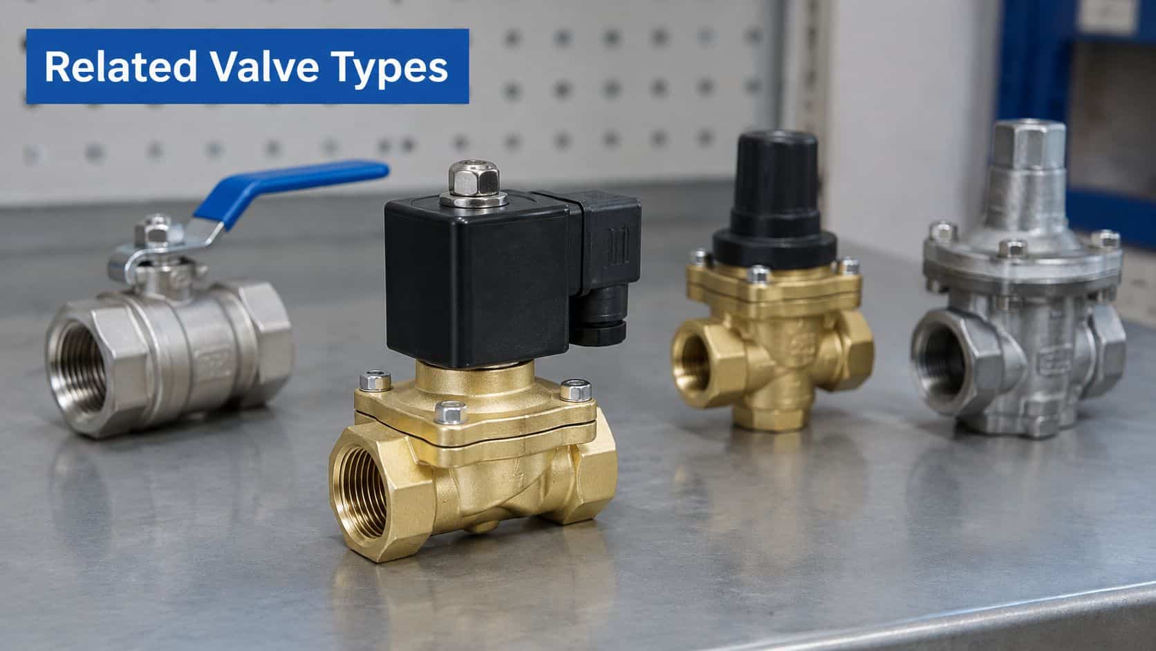
Compare the important properties
- Operator and coil voltage: Confirm that the replacement operator fits the electrical arrangement and control supply.
- Port or Kv at the working differential: Match the required performance, not just the stated connection.
- Seal type and fluid: Check the material against the circuit fluid and operating conditions.
- Original identification: Keep the manufacturer's name and original part number with the cross-reference so the comparison starts from a traceable component.
MA Hydraulics stocks the full OMT Group inline circuit valve range, Hoyea Cetop directional and proportional solenoid valves, Cetop modular valves and a range of Orta valves. Its OMT Group options include cross relief, flow divider/combiner, overcentre, pilot operated check, pressure reducing, priority flow control, pump unloader, relief, sequence and solenoid valves.
A nominal size match alone doesn't confirm equivalence. Compare the operating function, port arrangement, electrical interface, materials and performance before treating a substitute as interchangeable. Explore the range of 2-way solenoid valves when checking a two-port switching application, and send the original part number and datasheet to MA Hydraulics for help identifying the closest equivalent.
Confirm Your 15mm Valve Specification Today
The right valve comes down to three decisions: what 15mm refers to on the connection, whether the duty fits the component's operating window, and whether the fluid and approval status suit the installation. If any one is unclear, the label alone can't confirm the replacement.
Call MA Hydraulics Ltd on 01724 279508 today, or send a message. Include the original part number or datasheet, fluid type, pressure, temperature, coil voltage, connection standard, duty cycle and required flow so the selection can be checked against the actual application.
A written specification with every value stated gives the clearest basis for an accurate answer. Call or send the details today to confirm the valve before ordering.
MA Hydraulics Ltd supplies hydraulic and solenoid valve components for mobile and industrial applications, with support for component selection and cross-referencing. Visit MA Hydraulics Ltd to explore the valve range or contact the team about your 15mm valve specification.
