
The tipper body won't lower, the operator's holding the switch, and nothing happens at the valve. Before you order a replacement, establish whether the coil has lost its supply, the winding has failed, or the spool hasn't moved. A 24 V solenoid valve is an electrical component and a hydraulic component working together, and either side can stop the machine.
The expensive mistake is buying by voltage alone. Matching the coil marking won't correct the wrong spool function, an unsuitable duty rating or a control circuit that leaves the machine moving after the operator releases the switch.
What a 24V Solenoid Valve Actually Does
Say a hydraulic clamp won't release. The control switch should energise a coil, the coil should operate the valve mechanism, and the valve should connect the actuator to the intended oil path. If any part of that sequence fails, the clamp stays put even though the operator has given the correct command.
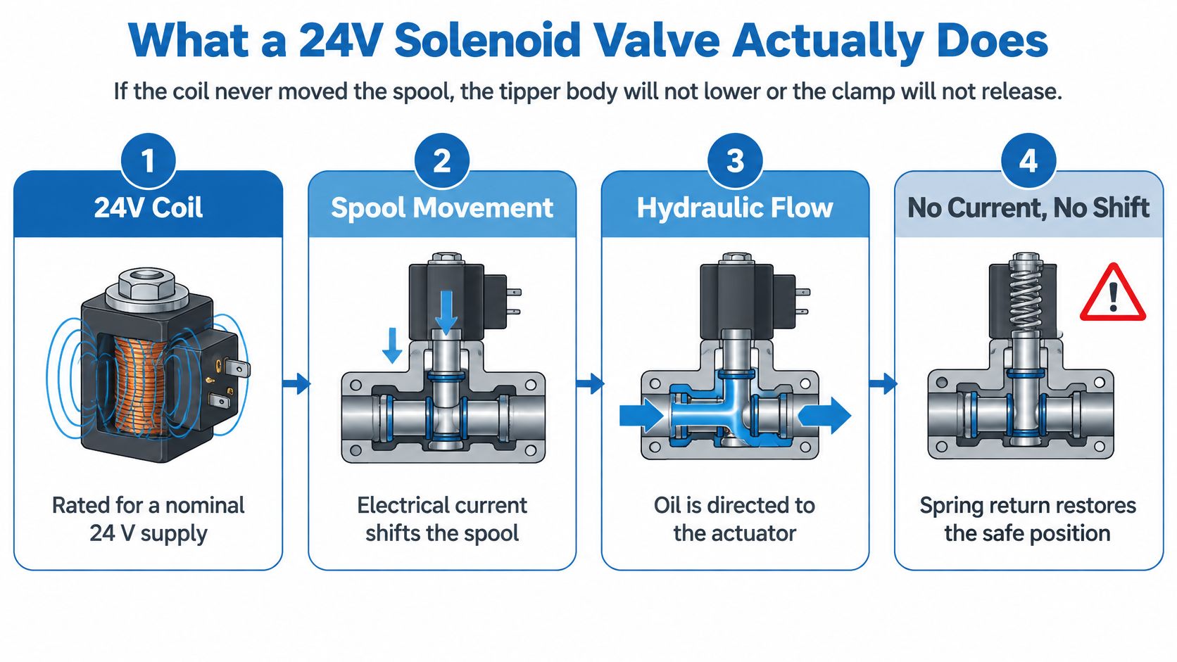
A 24 V DC solenoid valve uses an electromagnet designed for a nominal direct-current supply. Think of the coil as a switchable magnet and the spool as a sliding gate. Depending on the valve design, the magnet moves the spool directly or operates a pilot stage that shifts the main spool.
The operating sequence is illustrated below.
The coil and body have different jobs
The coil has electrical requirements: supply type, power, duty rating and connector arrangement. The valve body has hydraulic requirements: pressure capability, flow capacity, mounting pattern and internal connections.
On a directional valve, moving the spool connects pressure to a work port while providing the appropriate return path. On two-way solenoid valves, the function is simpler: opening or closing a flow path. Neither function can be identified reliably from the coil alone.
When current stops, a spring-return valve moves towards its specified rest position. A normally closed valve closes its controlled path, a normally open valve opens it, and a spring-centred directional valve returns to its centre condition.
Practical rule: The rest position is only a safe position if the complete hydraulic circuit makes it safe.
A centre condition that unloads a pump isn't necessarily suitable for holding a suspended load. Likewise, removing power doesn't guarantee that trapped hydraulic energy has disappeared.
Check the supply marking carefully. A coil marked for alternating current isn't interchangeable with a DC coil, even when the nominal voltage looks identical. Start with the electrical marking, then establish the hydraulic function before deciding whether the replacement is suitable.
Electrical and Mechanical Specs to Check First
Typical 24 V solenoid valve specifications
| Spec | Typical value | How to read it |
|---|---|---|
| Nominal voltage | Nominal DC rating marked on the coil | An AC coil isn’t interchangeable |
| Voltage at the coil under load | Within the manufacturer’s stated operating window | Measure at the pins, not the battery |
| Coil power | Use the exact wattage marked on the coil or datasheet | Power sets heat and current |
| Holding current at nominal voltage | Coil power divided by supply voltage | Check output capacity and simultaneous loads |
| Cold coil resistance | Nominal voltage squared divided by rated power, as a screening estimate | Resistance rises when hot; confirm against manufacturer data |
| Max pressure | Published limit for the exact body and operating condition | Taken from the valve body, not the coil |
| Flow | Published capacity at the stated pressure drop | Match the actual circuit requirement |
| Connector and enclosure | DIN Form A or the specified mobile connector, with the complete sealing arrangement | A loose plug doesn’t retain its enclosure rating |
| Ambient temperature | Manufacturer’s permitted ambient range | Check engine-bay exposure separately from insulation class |
| Shift time | Published response under stated test conditions | Cold, thick oil can slow movement |
| UK indicative price excl. VAT | Obtain a current written quotation in pounds sterling | Confirm coil-only or complete-valve scope, spool and brand |
Use this as a nameplate comparison sheet, not a universal set of ratings. There's no defensible generic pressure, flow or price that makes every replacement acceptable. Record pressure in bar, flow in L/min, dimensions in mm, and purchase prices in £, with VAT treatment clearly stated.
Measure the electrical supply where it matters
A healthy reading at the battery or power supply doesn't prove that the coil receives enough voltage. Measure across the coil connections while the output is commanded on and the winding is drawing current. A damaged switch, corroded terminal or long cable run can leave the source looking healthy while the valve receives an inadequate supply.
Don't assume a universal voltage tolerance. Use the operating window for the exact coil, including any restrictions associated with temperature or hydraulic loading.
The electrical relationships are useful for screening replacements:
- Current requirement: Divide rated power by rated voltage, then check that the controller can supply all coils that may operate together.
- Resistance estimate: Divide voltage squared by power, but don't treat this as a guaranteed cold-winding specification.
- Electronic coils: Built-in suppression or control electronics can affect meter readings, so compare using the manufacturer's test method.
Read the hydraulic limits separately
Flow ratings only make sense alongside the stated pressure drop. A valve that passes the required flow with excessive restriction can create heat and reduce actuator performance.
Check pressure limits for individual ports too. A permissible pressure at the pressure inlet doesn't automatically apply to the tank connection, particularly where seals or pilot arrangements impose restrictions.
Finally, compare the mounting face, seals, connector clearance and manual override access. Reject any mismatch before ordering, then confirm the exact replacement against its datasheet. A familiar-looking plug isn't evidence that the valve underneath will do the same job.
Where These Valves Work on Mobile Plant
The coil on a trailer, crane or factory manifold may look familiar, but each installation asks something different of it. Follow the oil path and the operating sequence rather than assuming that the electrical label defines the application.
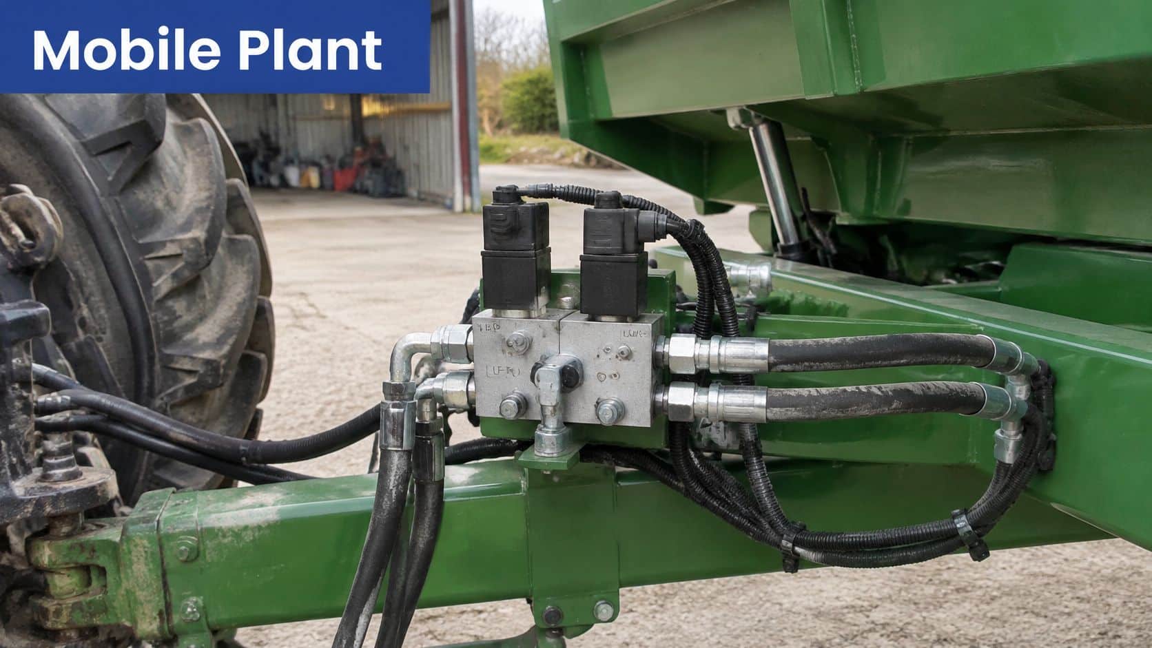
An agricultural installation also exposes the assembly to dirt, vibration and weather.
Tippers and materials-handling attachments
On an agricultural trailer tipper, the valve may admit oil to the lifting cylinder or release oil for lowering. Identify the pressure supply and tank return, then establish which actuator connection performs the lifting function. A single-acting cylinder doesn't need the same work-port arrangement as a double-acting actuator.
Check the flow arrow against the hoses and the circuit symbol. The easily missed specification is the valve's behaviour when the operator releases the command, particularly with a raised body. Never work beneath an unsupported body while investigating it.
A materials-handling clamp or rotator usually needs controlled movement in opposing directions. Pressure and tank serve the valve, while the work ports serve the actuator. Reversing those work connections may reverse the operator's command, but changing a spool without checking its internal paths can introduce a less obvious fault.
A clamp that stops moving isn't necessarily a clamp that holds its load securely.
For a clamp, check the load-holding arrangement and permissible leakage. For a rotator, check the neutral behaviour and whether the circuit provides the intended braking action.
Cranes, skip loaders and fixed power packs
On a lorry-mounted crane or skip loader, connector condition can matter as much as the coil. Spray enters a cracked housing or damaged cable seal, then corrosion develops at the contacts. Confirm pressure, tank and both work-port connections against the valve symbol, not the hose routing alone.
A pilot-operated cartridge may use a small solenoid stage to control a larger main stage. Here, adequate pilot conditions are the easily missed requirement: an energised coil can't compensate for missing pilot pressure.
A factory hydraulic power pack may use directional valves on a manifold beside modular relief, flow-control and check valves. Follow pressure and tank through the stack before tracing the work ports. Check the symbol and flow direction of every module, because a compatible mounting face doesn't establish a compatible circuit.
Across these machines, supply voltage may match while connector construction, hydraulic capacity and operating pattern differ. The replacement needs to suit the machine, not just fit the available plug.
Choosing Duty Cycle Coil and Safe Position
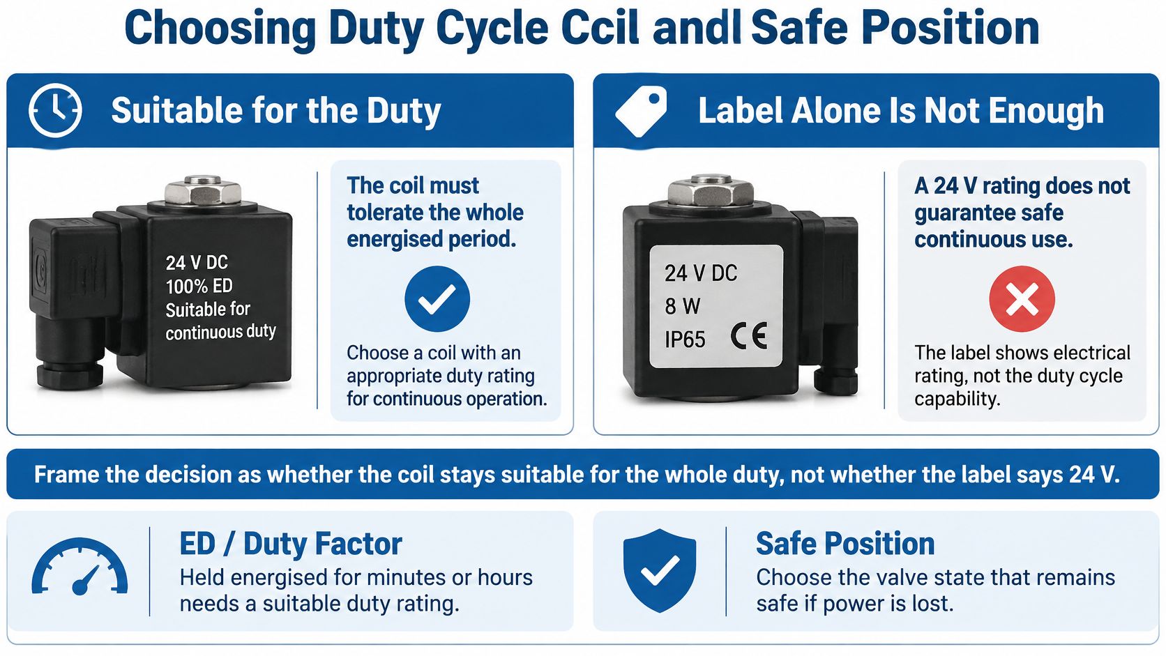
Will the coil tolerate the whole energised period? That's the question to settle before comparing replacement prices. A valve used for brief movements has a different thermal duty from one held energised throughout production.
UK distributor listings include pneumatic solenoid products rated at 2 W, illustrating why the nominal supply alone doesn't establish electrical demand, as shown in the RS pneumatic solenoid valve range. That figure belongs to the listed pneumatic products, not to every hydraulic coil.
The duty and power-off decisions should be considered together.
Coil duty choices for a 24 V valve
| Coil type | Use when | On power loss | Energy while held |
|---|---|---|---|
| Continuous-duty | The required hold can last throughout the operating period | Determined by the valve mechanism | Full rated holding demand unless controlled otherwise |
| Intermittent, with the specified ED rating | Short pulses remain within the stated on-time and cooling limits | Usually spring return where fitted | Lower average heat only if the duty limit is respected |
| Energy-saving or PWM hold | Long holds justify a compatible reduced-current controller | Must still spring-return if required by the safety design | High pull-in demand, then reduced holding current |
| Latching or bistable | Power is needed only to change state and staying put is acceptable | Stays in the last selected position | Little or no electrical holding demand |
Match the thermal duty to the command
ED, or duty factor, describes permitted energised operation under specified conditions. It isn't permission to keep an intermittent coil on indefinitely because the valve still appears to work.
A tied-down push-button or changed PLC sequence can turn an acceptable installation into an overheating problem. Check the permitted energised period, cooling interval, switching frequency and ambient conditions together. The duty-cycle guide explains the distinction between operating intermittently and holding continuously.
For an energy estimate, multiply rated electrical power by total energised time, then apply the site's electricity tariff. For a thermal assessment, also consider the valve's mounting, nearby heat sources and the manufacturer's restrictions. Annual consumption alone won't tell you whether the winding gets too hot during a long hold.
The demonstration below can support component identification, but the exact valve datasheet remains the selection reference.
Don't trade away the required return behaviour
A latching arrangement can reduce holding demand, but it's unsuitable where the machine must return automatically when electrical power disappears. Reduced-power control also needs the correct pull-in sequence and compatible output electronics.
Before accepting a substitute, check voltage tolerance, watts, ED, ambient range, switching rate, suppression, connector sealing, port pattern and de-energised function. An enclosure rating applies to the complete correctly installed assembly, not a damaged gland or missing gasket.
If any of those requirements differs, don't treat the valves as interchangeable.
Wiring and Commissioning Without a Surprise Shift
A low-voltage coil is not automatically a safe control circuit. The supply arrangement, protection and fault response determine whether an electrical failure produces a controlled stop or an unexpected movement.
HSE's electrical standards guidance identifies machinery standards including BS EN 60204-1 and BS EN 982, while the Electricity at Work Regulations 1989 require electrical systems to be operated and maintained without creating danger. Confirm the current applicable standards for the machine rather than treating an older standard reference as a complete compliance assessment.
Establish the supply and fault paths
SELV uses protective separation without an intentional earth connection. PELV also uses protective separation but permits an earth connection. Neither description can be assigned just because a power supply has a low nominal output.
Establish the intended circuit reference and protective bonding from the design. Don't join a return conductor to the chassis merely because another machine uses that arrangement. An unintended connection can bypass switching or create an unexpected energisation path.
The checklist highlights the integration checks, but the machine's risk assessment must determine the test conditions.
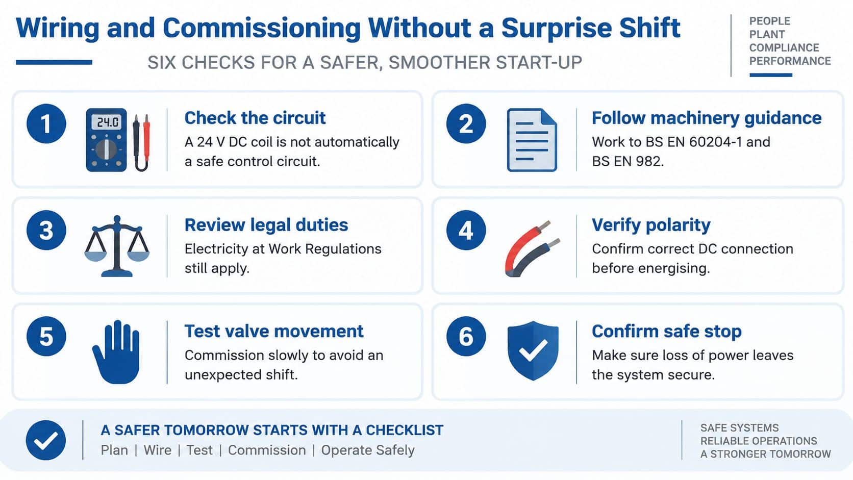
Commission with the load secured
-
Isolate and prove dead. Secure moving parts, release or restrain stored hydraulic energy, and identify the coil terminals and protective-earth connection from the datasheet. Don't assume every connector uses the same pin arrangement.
-
Complete the connector sealing. Fit the correct gasket, cable gland and strain relief. Check that the gland grips the cable sheath rather than individual conductors.
-
Confirm polarity. Follow the markings on the coil and plug. A built-in suppressor diode makes polarity significant, even where the bare winding would operate either way round.
-
Select compatible suppression. Use the manufacturer's specified diode or suppressor to protect switching devices. A simple flywheel diode can delay current decay and valve release, so check its effect on stopping behaviour.
-
Coordinate protection. Size the fuse or electronic protection for the conductor, output and load. Check both supply and return faults: some wiring faults can bypass a switching device without drawing enough current to trip protection.
-
Measure under load. Check voltage at the connected coil during actuation and with other relevant loads operating. Compare the result with the exact manufacturer's operating window.
-
Verify the resting hydraulic state. With personnel clear and the load restrained, confirm the specified de-energised connections using suitable gauges and controlled functional testing. A manual override can help diagnosis, but doesn't prove electrical power-off behaviour by itself.
-
Prove fault and emergency-stop behaviour. Have a competent person assess open-circuit, short-circuit, earth-fault and low-voltage responses using a controlled test method. Don't create live shorts as an improvised test.
Use the hydraulic circuit design basics to relate electrical commands to oil paths and stored energy.
Keep diagram labels consistent with the actual DC marking, polarity, port letters and flow arrows. Important information must also appear in readable text, not only inside an illustration, as explained in the Home Office guidance on accessible images.
Faults That Stop a 24V Coil Working
The operator presses the button, there's no click, and the function stays dead. Start with voltage at the connected plug under command, then isolate the supply and measure the disconnected winding's resistance. Those measurements separate several electrical faults before you disturb the hydraulic assembly.
Don't measure resistance on an energised circuit. Disconnect electronic suppressors or controllers where the manufacturer's test procedure requires it, otherwise the reading may describe more than the winding.
24 V solenoid valve symptoms and fixes
| Symptom | Likely cause | First check |
|---|---|---|
| No click and no movement | Open coil, no supply or failed switch | Volts at the plug, then isolated winding resistance |
| Fuse or trip opens at once | Shorted coil or chafed cable | Compare winding resistance with specification and inspect the harness |
| Voltage present but coil silent | Wrong coil specification, broken winding or failed mechanism | Check the marking and resistance against the correct datasheet |
| Clicks but no flow | Stuck spool, wrong centre, missing pilot or swapped hoses | Controlled override test and suitable pressure measurement |
| Coil too hot to touch | Unsuitable duty, high ambient or excessive supply voltage | Measure voltage and establish energised duration |
| Function stays on | Welded contact, back-feed or valve failing to return | Check whether the coil remains electrically commanded |
| Slow or weak only when cold | Supply sag combined with viscous oil | Measure during shifting and check oil suitability |
Separate a weak feed from a failed winding
An open winding reading indicates a broken electrical path, but inspect the coil terminals before condemning the winding itself. An unexpectedly low reading can indicate shorted turns, although a basic resistance test won't detect every insulation failure.
If the voltage collapses only when the coil is connected, investigate the supply path. Measure voltage drop across suspect connectors, switches and cable sections while current flows. A continuity buzzer can sound through a connection that still performs badly under load.
Replace the component that fails the test, not the component nearest the symptom.
A damaged plug or correctly diagnosed coil may be a straightforward repair. Replacing a fuse without finding the reason it opened is not a repair.
When the electrical command works but the hydraulics don't
A click confirms some mechanical action, not full spool travel or correct flow. Check supply pressure, pilot requirements, manual-override position and hose connections before removing the valve. A scored spool or damaged bore needs mechanical assessment, not a stronger electrical supply.
If the function stays active after release, establish whether the winding remains powered. Continued voltage points towards the control circuit or back-feed; no electrical command shifts attention towards return mechanics, the selected spool arrangement or trapped hydraulic pressure.
A hot surface alone doesn't prove failure, and touching it isn't a reliable temperature test. Compare operating conditions with the thermal specification, including nearby heat and mounting requirements. After any repair, prove the de-energised machine behaviour before returning it to service.
Confirm the Valve Then Call for the Right Part
A 24 V marking gives the nominal coil supply, not proof that the whole valve suits the circuit. Order against the identified component and required function. A coil-only replacement is reasonable when the winding has failed, the valve mechanism is sound and the replacement is approved for that valve family.
Record the details before removing anything:
- Electrical marking: supply type, nominal voltage, rated power, duty information and any suppression or electronics.
- Mechanical coil fit: armature-tube dimensions, coil height, retaining arrangement and connector clearance.
- Hydraulic identification: manufacturer, body or cartridge code, pressure rating and required flow.
- Circuit function: spool symbol, work-port arrangement, centre condition and required power-off behaviour.
- Mounting details: CETOP size, manifold pattern, cartridge cavity and seal requirements.
Choose a matching assembly
Photograph the nameplate, body markings and hydraulic symbol while they're still readable. Include the connector and mounting arrangement, but leave a cartridge or valve body untouched until the system has been isolated and depressurised.
Treat the coil marking as the start of the check. Intermittent duty, a sticking spool, trapped pressure or a shorted lead can make the correct voltage unsafe if the valve rests in the wrong position or stays energised longer than its rating allows. If the body is scored, the cavity doesn't match or the required rest position differs, a coil swap leaves the fault in place. Mobile and industrial manifolds need a compatible valve family, with the same porting, centre condition and power-off behaviour.
MA Hydraulics Ltd, based in Scunthorpe, stocks the full OMT Group inline circuit valve range, including solenoid valves, alongside Hoyea Cetop directional and proportional solenoid valves, Cetop modular valves and a range of Orta valves. The Hoyea range includes Cetop 3, 5, 7 and 8 directional valves.
Have the identifying details ready when you contact us. We can help with component selection and cross-references for hard-to-find coils and bodies, so the replacement addresses the fault without changing operating behaviour.
For help matching a coil, cartridge or directional valve, visit MA Hydraulics Ltd with the nameplate details, hydraulic function and mounting information to hand. We offer hydraulic valve selection support for mobile and industrial applications. Contact the team by phone or email, or send us a message to discuss the right replacement.
