
A loader arrives in the workshop with a familiar complaint. The lift circuit feels sluggish, pressure spikes are more noticeable, and the ride-control function no longer absorbs impacts as it did. The accumulator may still look sound from the outside, but a low or unstable nitrogen pre-charge can leave the bladder working outside its intended range and turn a minor service issue into expensive hydraulic damage.
A hydraulic accumulator charging kit gives you the means to measure and adjust that gas charge, but it isn't a tyre inflator with a different connector. The accumulator stores energy, the gas valve and adaptor must match, and the gauge must be suitable for the pressure range. The gas pre-charge is also separate from hydraulic system pressure, so connecting a gauge while oil remains trapped on the fluid side can produce a misleading and unsafe reading.
The same discipline applies across agricultural machinery, mobile plant and industrial systems. If you're investigating wider machine symptoms, a properly selected hydraulic accumulator sizing guide helps establish whether the vessel itself is appropriate before you adjust it. For related engine diagnostics, a separate compression test can help you detect diesel engine wear early.
Why Correct Pre-Charge Protects Your Hydraulic System
The symptoms usually arrive before the failure
A press clamp may take longer to reach pressure, then overshoot when the valve changes state. On a tractor or loader, the warning signs can be harsher ride control, increased frame vibration, or a repeated knock in the pipework. These symptoms do not prove that the accumulator has lost pre-charge, but they justify checking the gas pressure against the manufacturer's specification.
Nitrogen acts as a controlled gas spring behind the bladder or piston. Hydraulic oil enters the fluid side and compresses that gas, allowing the vessel to absorb pulses, store flow and cushion movement. With too little pre-charge, the bladder can travel into parts of the shell or valve arrangement outside its intended operating range. With too much, the accumulator accepts too little oil, reducing damping and usable capacity.
Workshop rule: Treat the accumulator as pressure equipment first and a service item second.
That rule should guide kit selection. A high-reading gauge alone is not enough. The charging head, adaptor, hose, isolation arrangement and regulator must suit the accumulator, nitrogen bottle and manufacturer's pressure limits. Gauge resolution matters too, because an approximate reading can lead to an incorrect setting even when the gauge's maximum range looks suitable.
If the accumulator itself may be incorrectly sized for the circuit, check a hydraulic accumulator sizing guide before changing its charge. For a separate engine fault, a compression test can help you detect diesel engine wear early.
The UK boundary matters
The Pressure Systems Safety Regulations 2000 came into force on 21 February 2000. They address serious injury from stored energy released by a failed pressure system or component. Their relevance to accumulator work is practical: isolate the system, verify pressure, follow a controlled procedure and use suitable protective devices. The Pressure Systems Safety Regulations 2000 can help define the site's pressure-safety arrangements.
Hydraulic systems using hydraulic oil are generally outside PSSR because hydraulic oil is not a “relevant fluid” under the regulations. That boundary does not remove the hazard from a gas-loaded accumulator. The vessel can still contain substantial stored mechanical energy, so competent handling and correctly rated charging equipment remain necessary.
The Pressure Equipment (Safety) Regulations 2016 apply in Great Britain to pressure equipment and assemblies with a maximum allowable pressure above 0.5 bar, subject to exclusions and classification limits. That threshold is 0.5 bar above atmospheric pressure, considerably below the working pressures found in many industrial hydraulic accumulators. The UK government guidance on the Pressure Equipment (Safety) Regulations 2016 explains the regulatory scope and conformity context.
Check the accumulator nameplate, record pressure in bar, isolate the hydraulic circuit and match every adaptor, hose and gauge to the vessel's connection and pressure requirements. Never treat a charging kit as a substitute for confirming the accumulator's condition or the machine's isolation state.
What Is Inside a Charging Kit and How to Choose
A reliable kit has several separate jobs to perform. The charging head connects to the gas valve, the adaptor creates the correct interface, the hose carries nitrogen under pressure, the gauge shows the measured pre-charge, and the regulator controls the supply from the bottle. If any one of those parts is wrong, the presence of the others doesn't make the assembly safe.

Compare the components, not just the price
A universal charging head can be useful for a service fleet, but “universal” doesn't remove the need to verify the valve interface. Some accumulators use different gas-valve arrangements or thread standards, and a forced adaptor can damage the core or fail to seal. A dedicated head may cost more, but it reduces the temptation to improvise.
The hose should have a rating suitable for the accumulator's maximum permissible pressure and the controlled nitrogen supply. Look for sound fittings, legible identification and instructions that explain connection, isolation and bleeding. A short hose can be easier to control in a crowded service bay, while a longer hose may keep the bottle away from the machine. Neither choice compensates for an unsuitable pressure rating.
A gauge with a narrow, appropriate range is generally easier to read accurately than an over-ranged dial. Choose a calibrated gauge marked in bar and capable of showing the manufacturer's target without forcing you to estimate between widely spaced graduations. The regulator is essential when bottle pressure exceeds the accumulator's maximum permissible operating pressure. It gives the operator controlled flow instead of exposing the kit to an uncontrolled bottle connection.
The HSE states that the Pressure Equipment (Safety) Regulations apply above 0.5 bar, subject to their exclusions and classification limits. New equipment placed on the market in Great Britain must generally be UKCA- or CE-marked and supplied with English instructions. The HSE pressure equipment safety guidance is useful when retaining evidence for purchased equipment. For wider stores control, a practical guide to maintenance repair operations buying can help structure records for hoses, adaptors, gauges and replacement parts.
Charging Kit Compatibility Checklist
| Component | What to Check | Accept Criteria |
|---|---|---|
| Charging head | Gas-valve design and connection | Fits the specified accumulator valve without force or improvised seals |
| Gas-valve adaptor | Thread, sealing method and valve-core access | Matches the accumulator manufacturer’s connection standard |
| Pressure gauge | Calibration, units and readable range | Suitable bar range for the target pre-charge and traceable calibration |
| High-pressure hose | Pressure rating, length and fittings | Rated for the intended service and free from damage |
| Isolation and bleed valve | Positive shut-off and controlled hose release | Allows the bottle and hose to be isolated and depressurised safely |
| Regulator | Bottle compatibility and outlet control | Limits supply pressure below the equipment’s permissible operating conditions |
| Instructions and records | English operating information and identification | Retained with calibration, ratings and compatibility evidence |
A carrying case is more than a convenience on mobile plant. It protects the gauge, charging head and adaptors from contamination and makes it less likely that the correct parts will be replaced by an unsuitable connector from another kit. MA Hydraulics Ltd can also advise on accumulator charging equipment and related hydraulic components where the valve, pressure or application isn't clear.
Preparing the Accumulator for Safe Nitrogen Charging
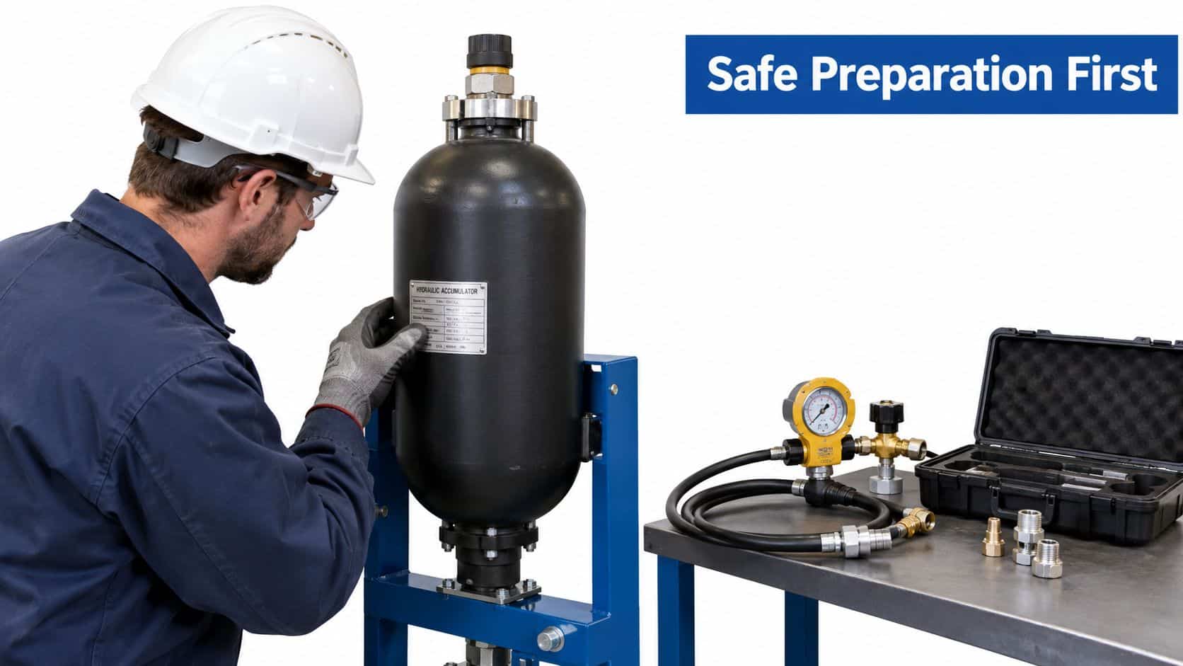
A small preparation error can turn a routine pre-charge check into an uncontrolled release of stored energy. Start with the accumulator nameplate and manufacturer's documentation. Record the vessel type, volume, maximum working pressure, specified pre-charge, temperature and date. Compare the target with the machine builder's stated tolerance before connecting a charging kit.
Lock off the hydraulic energy
Shut down the power source and prevent an unexpected start. Isolate the accumulator from the hydraulic circuit using the machine's specified method, then discharge the fluid side fully before measuring or applying nitrogen pressure. Oil pressure left in the circuit can oppose the gas charge and produce a misleading gauge reading.
Inspect the vessel for dents, corrosion, damaged fittings and signs of movement. Check the charging hose, couplings, adaptor and gas-valve core. A worn seal or damaged coupling may leak under pressure. Dirt at the gas valve can also prevent the charging head from seating correctly.
The Pressure Systems Safety Regulations 2000 address serious injury risks from stored energy released through failure of a pressure system or component. Their requirements support controlled isolation, verification, competent work and suitable protective devices. Apply those controls alongside the accumulator manufacturer's instructions.
Control the nitrogen supply
Use dry industrial nitrogen only. Oxygen and compressed air are unsuitable because the specified gas is part of the accumulator's safe operating arrangement. Secure the bottle, confirm that the regulator matches its connection, and check that the hose and gauge are rated for the intended pressure.
Only qualified personnel should carry out the work. The operator needs to understand the accumulator design, the machine's isolation points and the charging kit before opening the gas valve. On UK plant, competence and the equipment's pressure-system boundaries both matter, even when the practical task is checking pre-charge.
Before nitrogen flows, confirm the following:
- Nameplate limits: Maximum working pressure and vessel identification are visible and understood.
- Target pre-charge: The manufacturer's specified value and tolerance are available, not an assumed universal percentage.
- Fluid-side condition: Hydraulic pressure is isolated and discharged.
- Kit condition: Gauge, hose, adaptor, charging head and bleed valve are undamaged and compatible.
- Bottle control: The nitrogen bottle, regulator and outlet pressure suit the kit and accumulator.
- Work area: Personnel are clear of discharge paths and the vessel is supported as intended.
Finally, check that the gas-valve core is present, clean and seated before fitting the charging head. If it is loose, damaged or contaminated, stop and correct that fault first. A charging head that will not seat squarely should be treated as a compatibility or valve problem, not forced into position with extra sealant or improvised adaptors.
How to Charge and Set Nitrogen Pressure Accurately
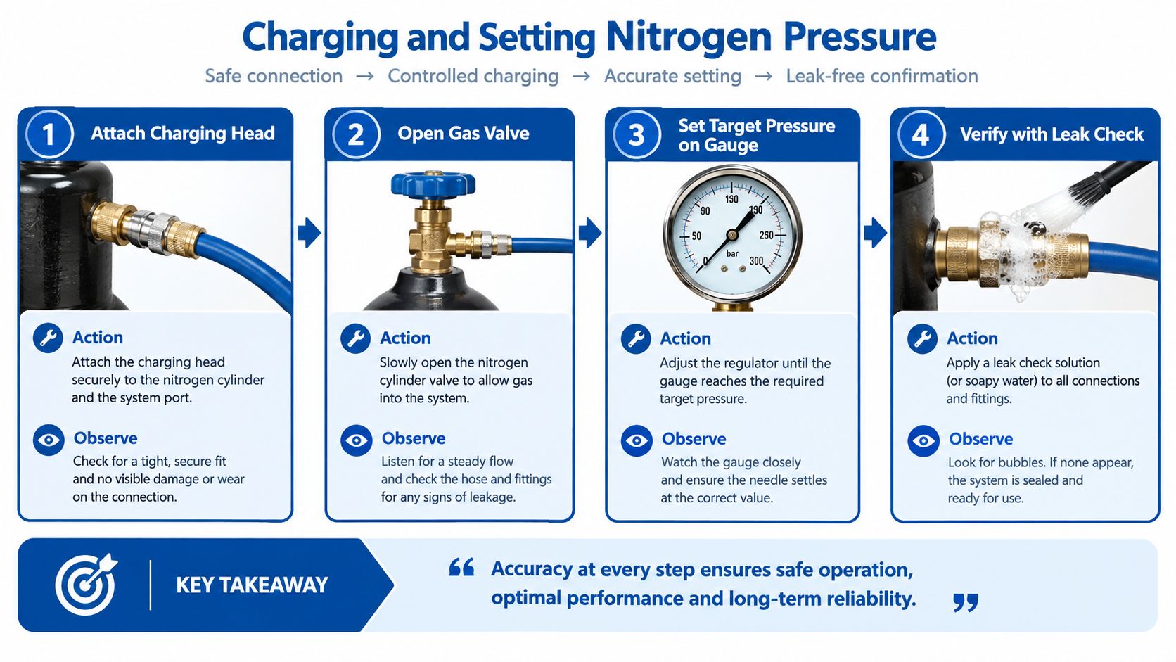
Fit the correct adaptor to the accumulator gas valve without forcing the thread. Connect the charging head and hose, check that the bleed valve is closed, and confirm that the nitrogen regulator is set for controlled delivery. The accumulator must remain isolated from the hydraulic circuit, with the fluid side discharged, before you measure or charge it.
Parker's UK operating instructions require the accumulator to be identified, isolated, shut down and discharged before nitrogen pressure is measured or applied. The relevant Parker accumulator operating instructions should take priority where they specify a different connection or operating sequence for the vessel in front of you.
Open the supply gradually
Use a pressure-reducing regulator whenever bottle pressure exceeds the accumulator's maximum permissible operating pressure. Open the regulator slowly. A rapid gas flow can create adiabatic heating and shock loading, both of which place unnecessary stress on the charging assembly and vessel.
Pressure-control rule: Open the nitrogen supply gradually, watch the gauge continuously and stop at the manufacturer's specified pre-charge. A high gauge reading isn't proof that the setting is correct.
Charge towards the target in bar, allowing the reading to settle rather than chasing a moving needle. The correct value comes from the accumulator manufacturer or machine builder, not from a generic percentage applied across different vessel types and duties. If the gauge rises unexpectedly or the connection leaks, close the supply and investigate rather than compensating by opening the regulator further.
Once the reading reaches the target, close the accumulator gas valve as specified by the charging-head design. Isolate the nitrogen bottle, then bleed the hose safely before removing the head. Keep your hands and face clear of the connection while the hose is being depressurised.
Verify the finished setting
After the pressure stabilises, check the gauge again. Inspect the gas-valve connection for leakage using the site's approved method, and confirm that the valve cap or protective arrangement is refitted. Record the final pressure, temperature, date, accumulator identification and the equipment used.
If you need a replacement instrument, select a hydraulic pressure gauge with a suitable bar range and calibration status. A gauge that displays more pressure than the accumulator requires isn't automatically more useful. Readability, compatibility and traceability are more important than an impressive maximum figure.
The embedded demonstration should be checked at its rendered size before publication. Test the player on desktop and mobile screens, confirm that the frame keeps its intended 16:9 proportion, and ensure that captions, spoken technical terms and the transcript have been reviewed rather than accepted without checking.
Safety Checks and Mistakes to Avoid During Charging
Most charging errors come from a plausible assumption. An operator sees a pressure gauge, connects it to a valve and expects the displayed value to represent the accumulator's pre-charge. That assumption fails if hydraulic pressure remains on the fluid side, if the adaptor doesn't open the gas valve correctly or if the gauge isn't calibrated.

Challenge the common shortcuts
- Confusing system pressure with pre-charge: Hydraulic operating pressure and nitrogen pre-charge are different measurements. Isolate and discharge the fluid side before relying on the gas gauge.
- Opening the bottle regulator quickly: Fast flow can heat the gas and shock the vessel. Use controlled regulation and watch the gauge.
- Exceeding the accumulator rating: A regulator, hose and gauge must all be suitable for the vessel. Stop if the nameplate limit or connection details aren't clear.
- Using an incompatible adaptor: A threaded connection that feels nearly correct isn't acceptable. Match the charging head to the gas valve and sealing arrangement.
- Trusting an uncalibrated gauge: A clean dial can still be inaccurate. Retain calibration evidence and use an instrument appropriate to the expected bar range.
- Ignoring a falling reading: A repeat loss of pre-charge may point to leakage at the valve core, bladder or shell. Repeatedly topping up without finding the cause isn't a repair.
HSE guidance treats stored pressure energy as the central hazard and expects suitable operating limits, competent examination, maintenance, instructions and records for applicable systems. Qualifying systems may require a written scheme of examination covering relevant pressure vessels and protective devices, as set out in the Pressure Systems Safety Regulations.
Check the published material too
Technical content can create avoidable risk when the visual details are wrong. Before publishing a charging demonstration, check every pressure unit, valve label, adaptor name and warning inside the image. A diagram that says bar must show bar clearly, and the wording must match the equipment being demonstrated.
Videos need the same attention. Confirm the frame size at the rendered desktop and mobile layouts, review synchronisation and spelling in the captions, and provide a transcript. GOV.UK accessibility guidance recommends switchable closed captions, checked automated captions and a transcript, especially where technical words may be misrecognised. The UK accessibility standards guidance also supports text alternatives for images containing meaningful information.
Meaningful images need useful alternative text, not a filename. Check contrast in diagrams, tables and icons so warnings and bar values remain legible. NHS accessibility guidance recommends a minimum 3:1 contrast ratio for non-text content, including images, charts, tables and icons, and supports accurate captions, transcripts and nearby written summaries in technical media. See the NHS content accessibility guidance before the article goes live.
Keeping Records and Getting Expert Support in the UK
A charging job isn't complete when the gauge reaches the target. The useful record identifies the accumulator, records the target and measured pre-charge, notes the temperature and date, and names the charging equipment used. Add the final pressure, operator and any observations about the valve, hose, couplings or vessel condition.
Use rechecks to find slow losses
A practical commissioning routine is to recheck the pre-charge within the first week, again after three months, and then at intervals of 12 months or less, depending on the machine builder's risk assessment and duty cycle. These intervals come from the supplied UK accumulator servicing guidance, not from a universal rule for every vessel.
A falling reading deserves investigation. Check the valve core and connection first, then consider bladder or shell leakage if the loss continues. A record of repeated readings gives a competent engineer useful evidence that a charge is stable, rather than encouraging repeated adjustment without diagnosis.
Retain the charging kit's calibration information, hose and adaptor ratings, operating instructions and compatibility details. Where the equipment falls within applicable pressure-system arrangements, keep examination and maintenance evidence with the machine records. A structured documentation management service can help maintenance teams keep those records accessible and linked to the relevant equipment.
Know when to bring in a competent person
The HSE says PSSR applies to the safe design and use of pressure systems, with the aim of preventing serious injury from stored energy released when a pressure system or component fails. For accumulator servicing, that supports treating the vessel, gas valve, hose, charging head and protective devices as a connected pressure-safety task. The HSE guidance on PSSR explains when written schemes and competent examinations apply to qualifying equipment.
Don't let a premium kit create false confidence. A well-made case and polished gauge won't compensate for the wrong adaptor, an unsuitable regulator or a procedure that leaves trapped hydraulic pressure in the circuit. When the accumulator specification is uncertain, the pre-charge keeps falling or the machine can't be safely isolated, stop and obtain competent technical support.
MA Hydraulics Ltd can help with accumulator charging equipment, component selection and pre-charging requirements for mobile and industrial applications. The team can also assist with hard-to-find hydraulic parts, cross-references and related assemblies where the charging problem exposes a wider system issue.
Call MA Hydraulics Ltd on 01724 279508 today for help selecting a compatible hydraulic accumulator charging kit or arranging practical support with accumulator pre-charging. You can also send MA Hydraulics Ltd a message with the accumulator details, valve connection and pressure requirements.
