
A lot of people land here after the same annoying workshop problem. Someone asks for 3/8 copper tubing, somebody else orders 10 mm copper tube, and the parts arrive looking close enough to tempt a rushed fit-up. Then the olives don't sit right, the bend looks slightly off, or the pressure rating on the paperwork doesn't match what the circuit needs.
That confusion isn't trivial. On a small hydraulic pilot line, lubrication circuit, or refrigeration run, “close enough” is where rework starts. One wrong assumption at stores counter level can ripple into wasted fittings, awkward routing, and time lost on a job that should've been straightforward.
The trouble is that 3/8 copper tubing still survives in everyday trade language, while UK technical practice has largely moved to metric sizing and standard-based specification. If you've ever stood with a vernier in one hand and an old note pad in the other, that gap will feel familiar.
Introduction to 3/8 Copper Tubing in UK Systems
A technician in a farm workshop pulls a damaged line from a sprayer, reads “3/8 copper” on an old job note, and sends stores for a replacement. Back comes a coil marked 10 mm. It looks close enough on the bench. Then the fitting grip feels wrong, the bend radius changes, and confidence in the repair starts to slip.
That small mismatch catches out plenty of UK buyers and fitters because the name and the dimension are not the same thing. 3/8 copper tubing belongs to older imperial trade language, but the tube now sold and specified in the UK is usually presented in metric terms. The number that settles the argument is the true outside diameter. 3/8 inch equals 9.53 mm OD, not 10 mm, and that difference matters once fittings, clearances, and pressure all come into play.
A tube specification works like a full bearing number rather than a nickname on the shop floor. The name gets you into the right area. The actual choice comes from the hard details. With copper tube, those details are outside diameter, wall thickness, and temper.
Why this size still appears in UK work
Small copper tube still earns its place. You see it on pilot lines, lubrication runs, light hydraulic control circuits, refrigeration pipework, and agricultural machines where tidy routing and corrosion resistance matter. In those jobs, copper sits in the middle ground between rigid pipe and flexible hose. It holds a shape better than hose, but it is easier to form and route than heavier steel tube.
The language around it has not caught up evenly. Older drawings, maintenance notes, and verbal orders still say 3/8 copper because that is how the system was first described. Modern UK specification practice, though, follows metric outside diameter and wall thickness, as defined under BS EN 1057 for sanitary and heating applications. So the workshop may speak one language while the stockholder, the standard, and the data sheet speak another.
Where errors usually start
The first error is treating 3/8 inch as a rough label instead of a measured size. The second is assuming that near enough in diameter means interchangeable in service. The third is forgetting that two tubes with the same OD can behave differently if the wall thickness or temper changes.
That last point catches people by surprise. A 9.53 mm OD tube is only the outer skin of the specification. Change the wall, and you change the bore, stiffness, and pressure capability. Change the temper, and you change how readily it bends, how springy it feels in the hand, and how it responds during installation.
Workshop rule: If an order says only “3/8 copper,” the job is still half specified.
In UK buying terms, that also affects cost and availability. Suppliers may list the tube by metric OD, by imperial trade size, by coil or straight length, and by temper, all with prices in GBP that look similar until the specification is read properly. Getting the naming right at the start saves wasted fittings, repeat orders, and a line that has to be remade because “close” turned out not to be correct.
Understanding 3/8 Copper Tubing Dimensions and Standards
A fitter pulls an old copper line off a machine, walks to stores, and asks for “3/8 tube.” If the person at the counter hears that as a rough imperial label instead of a precise outside diameter, the replacement can be wrong before the box is even opened.
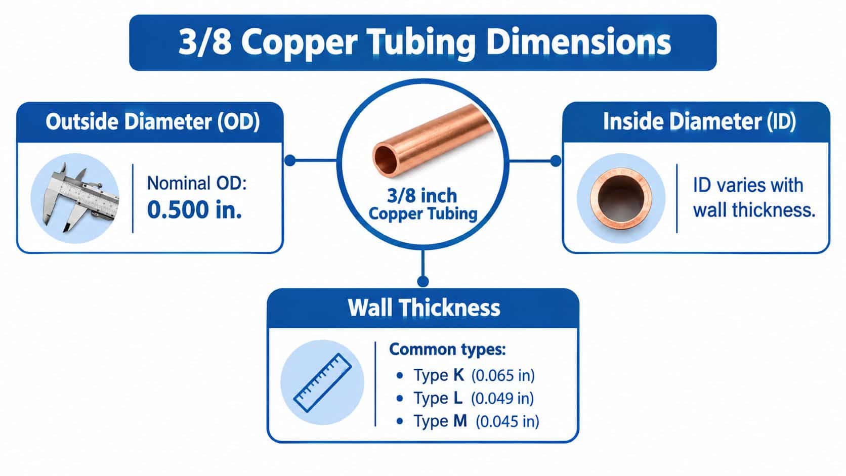
In UK practice, 3/8 copper tubing means 9.53 mm outside diameter, or 9.52 mm in some conversion tables, and that is the dimension worth fixing in your mind first (metric to imperial pipe conversion reference). The imperial name survives in everyday workshop language, but the actual tube is bought, measured, and matched by metric OD.
Start with outside diameter
For UK sanitary and heating tube, BS EN 1057 sets the habit of specifying copper by outside diameter and wall thickness. That matters on the workshop floor because fittings, clamps, clips, and bending tools all meet the tube on its outside surface first. If the OD is wrong, nothing else downstream lines up properly.
So the useful question in stores is simple. Ask for 9.53 mm OD copper tube, then confirm the wall thickness and temper needed for the job.
Then work inward
Inside diameter, or ID, is not a starting point. It is a result of the OD and the wall you choose.
A tube works like a tunnel with a fixed outer shell. The shell decides whether the tube fits the fitting and the clamp. The wall thickness eats into the space in the middle, so two tubes with the same 9.53 mm OD can have different bores. That changes both flow area and pressure capability. More wall usually means less bore and more strength under pressure. Less wall usually means more bore and less margin.
Two pieces of 3/8 copper tube can look identical on the outside and behave differently in service.
Why 3/8 inch and 10 mm get confused
The numbers are close enough to tempt people into treating them as interchangeable. In practice, that shortcut causes trouble.
A 3/8 inch tube is 9.53 mm OD, while 10 mm tube is 10 mm OD. The difference looks small on paper but shows up quickly when you try to seat an olive, form a flare, or clamp the line neatly. Add wall thickness differences, and the gap gets wider in practical terms. A plain-language UK size reference lays out those nominal relationships between imperial trade sizes and metric tube dimensions (UK copper pipe sizes reference).
This is the same kind of mix-up engineers see when tube size and thread size meet at one connection point. If you are sorting out both at once, this guide to adapting 1/4 BSP threads to metric fittings helps show where the tube standard ends and the port standard begins.
The short version is practical. 3/8 copper is a trade name. 9.53 mm OD is the starting dimension. After that, wall thickness and standard determine whether the tube suits the pressure, the fitting, and the job in front of you.
Grades Types and Temper Options Explained
Once the size is clear, the next question is what kind of copper tube you're holding. Apprentices often learn the hard way that 3/8 copper tubing isn't one material behaviour. It can be soft and easy to coil around a route, or stiff enough that it wants to stay straight unless you bend it properly.
The key word is temper.
What R220 R250 and R290 mean in practice
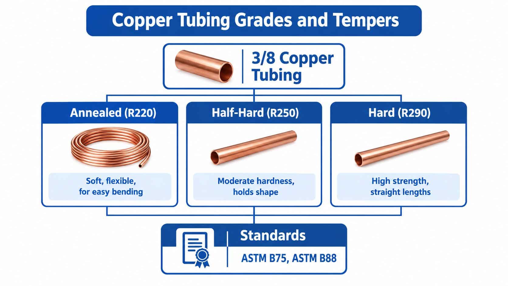
In the UK HVAC and refrigeration market, 3/8 inch copper tube is commonly supplied as 9.53 mm outside diameter with 21 SWG wall thickness (0.032 in) and made to BS EN 12735-1 in annealed R220 soft condition for coils. One UK supplier lists a 10 m coil, an internal diameter of 0.319 in, and a maximum working pressure of 1,076 psi, which shows how wall thickness and temper affect both flexibility and service capability (Lawton Tubes straight and coil product information).
That description tells you several things at once:
- R220 annealed: softer, easier to bend, commonly sold in coils
- 21 SWG wall: a defined wall thickness that helps determine pressure capability
- 9.53 mm OD: the actual outside size behind the 3/8 inch label
If you're routing round a tight cabinet or along awkward plant geometry, R220 is far friendlier to install than a harder straight length. But softness comes with trade-offs.
Why harder tube often carries more pressure
Independent UK and Europe market material notes show a sharp difference in working pressure for the same 3/8 inch outside diameter and wall depending on temper. One source lists 75 bar in R220 annealed form, 99 bar in R250, and 119 bar in R290 (UK copper tubes and pipes market report).
That's the sort of detail many articles skip, and it's exactly the detail that matters in real plant work.
A simple way to think about it is this:
- R220 annealed bends more easily and suits coil supply
- R250 gives a middle ground
- R290 is harder and better at holding straight runs and higher working pressure for the same size and wall
Workshop advice: Don't choose temper by habit. Choose it by route, support, and pressure.
Standard and supply form matter too
The standard also tells you what family of service the tube was made for. BS EN 12735-1 turns up in refrigeration and air-conditioning supply. BS EN 1057 is the familiar UK standard family for water and gas tube in sanitary and heating applications.
That doesn't mean you can ignore the duty of the line. It means you need to read the product description and check whether the form fits the job. Coils suit sweeping runs and compact installation. Straight lengths suit clean support spacing, neater alignment, and applications where stiffness is an advantage.
Typical Uses in Hydraulic and Agricultural Systems
A fitter tracing a fault on a compact power pack often finds that the main pressure line is not the awkward part. The awkward part is the small line tucked behind a guard, carrying a signal, a gauge feed, or a modest flow of oil where a bulky hose would crowd everything around it. That is where 3/8 copper tubing, meaning 9.53 mm outside diameter in real terms, often earns its keep in UK systems.
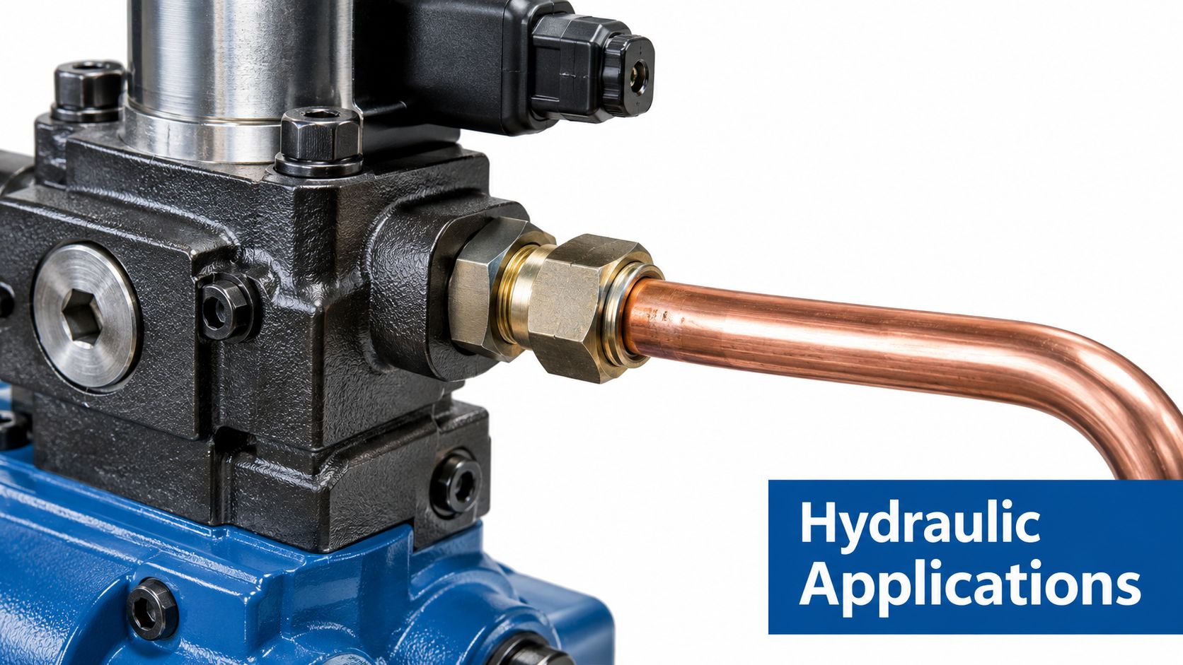
Copper in this size usually suits auxiliary duty rather than the main heavy feed. On the workshop floor, that means pilot lines, pressure sensing runs, instrumentation feeds, lubrication branches, and other low-volume circuits where neat routing matters as much as raw strength. A rigid small-bore tube works like a pre-set track. Once you bend and clip it properly, it stays where you put it.
Mobile hydraulic packs are a good example. A short sensing line from a manifold to a gauge or switch may need to pass through a cramped space with very little spare room. Hose can bow outward, rub on nearby parts, or need a larger bend radius than the machine really allows. A 3/8 tube gives a cleaner route and a tidier installation.
Agricultural machinery brings a different set of pressures, and not only hydraulic pressure. Mud, fertiliser residue, washdown, vibration, and improvised field repairs all influence what survives. In those conditions, 3/8 copper tubing can suit sheltered service lines, instrument feeds, and compact oil runs where corrosion resistance and easy forming are useful. It is often chosen for the awkward supporting jobs around the machine, not the jobs that carry the full workload.
That distinction matters.
A lot of confusion starts because buyers hear 3/8 inch and picture only one tube. In practice, the 9.53 mm OD may stay the same while wall thickness changes the bore and the pressure capability, and temper changes how the tube behaves once installed. Two tubes can both be sold as 3/8 copper and still suit very different duties. One may bend happily around a tight route for a gauge line. Another may be better for a straighter supported run where higher stiffness helps.
Where it tends to work well
- Pilot and control lines where fluid volume is low and routing accuracy matters.
- Gauge and pressure switch feeds where a stable, compact run helps keep the installation tidy.
- Lubrication branches on machinery with short distribution runs.
- Instrumentation lines on plant and mobile equipment.
- Agricultural service lines in protected positions around frames, tanks, and guards.
The practical comparison with hose or steel tube is simple. Hose is forgiving and good with movement, but it takes space and needs support to avoid chafing. Steel tube handles harder duty, but it takes more effort to form and protect. Copper sits in the middle for the right job. It is easier to shape neatly than steel and holds its route better than unsupported flexible line.
The catch is vibration. A tube clipped well at sensible intervals can give years of steady service. A tube left spanning a vibrating gap will work-harden, fret at supports, and crack at the fitting or bend. Apprentices often focus on material first and support second. In real service, the clip position and route can matter just as much as the metal.
Plant buyers also need to keep the wider factory context in mind. A small component choice can affect maintenance visibility, stockholding, and line uptime, which is why some teams also compare AI solutions for auto plants when reviewing production systems and procurement controls. The software does not choose the tube for you, but it can help track where each specification is being used and ordered.
In short, 3/8 copper tubing fits best where the run is compact, the flow is modest, and the installation benefits from a tube that can be formed neatly and held in place. Use it like a precise service line, not as a default answer for every hydraulic circuit.
How to Choose the Right 3/8 Copper Tubing for Your Application
Good selection starts with one honest question. What is this line doing?
If the answer is vague, the tube choice will be vague too. A drain-back line, a pilot line, a refrigeration coil, and an instrument run might all be described casually as 3/8 copper tubing, but they don't ask the same things from the material.
The decision points that matter
Start by checking these factors before you pick stock:
- Service pressure: This narrows the acceptable wall and temper quickly.
- Temperature exposure: Heat changes what's sensible for both jointing method and safety margin.
- Routing difficulty: Tight bends favour softer coil; long straight exposed runs often benefit from harder tube.
- Flow requirement: Small changes in bore matter more than people think on compact circuits.
- Joining method: Compression, flare, soldering, and brazing each suit different duties and skill levels.
- Supply description: UK listings may mix imperial naming with metric dimensions, so read every line of the product spec.
If you're buying online, check product imagery carefully too. Make sure wording shown within images matches the written description, and if a supplier embeds video demonstrations, the frame should display correctly so details such as wall designation or tube form aren't cropped.
Selection matrix
| Temper and Form | Typical Wall | Working Pressure | Best Use Case |
|---|---|---|---|
| R220 annealed coil | 21 SWG, 0.032 in where specified in refrigeration supply | Lower than harder tempers for the same OD and wall | Tight bends, compact routing, refrigeration and service coils |
| R250 straight length | Varies by product specification | Higher than R220 for the same OD and wall | General straight runs where some extra stiffness helps |
| R290 hard straight length | Varies by product specification | Higher again where the same OD and wall are compared | Neat straight installations, stronger shape retention, higher-pressure duty within the product rating |
Join selection to tube selection
People often separate tube choice from fitting choice. In practice, they belong together.
Compression fittings can be convenient, especially for maintenance access. Flare joints suit some service conditions very well. Soldered or brazed joints need heat and skill, but they can be appropriate where a permanent metal joint is wanted. Your tube temper affects how easily each method goes together and how forgiving the assembly feels during installation.
A clamp arrangement matters too. Poor support turns a correct tube into a future fault. If you're planning retention and vibration control, this guide to a clamp for tubing is useful background when laying out a clean run.
The best specification is the one that tells stores, fitters, and buyers the same story.
Joining Methods Pressure Limits and Maintenance Essentials
A copper line doesn't fail because the catalogue said “3/8”. It fails because the joining method, support, pressure margin, or inspection standard didn't match the duty. That's why installation and upkeep deserve as much attention as the tube itself.
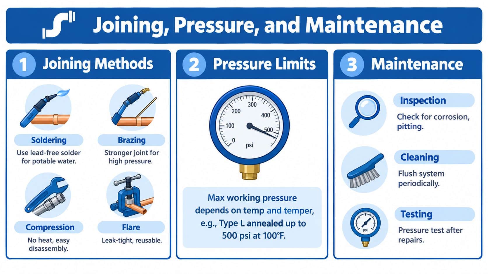
A useful visual summary sits below.
Choosing the joint
Each joining method brings its own strengths and its own traps.
- Compression fittings: Fast to assemble and handy where future disassembly matters. They reward clean cuts, correct insertion, and proper tightening. Overtightening can be just as troublesome as undertightening.
- Flare joints: Often a sound choice where a metal-to-metal seal is wanted and the fitting system is built for it. They need a proper flare tool and good tube preparation.
- Soldered joints: Common in lighter-duty copper systems, but they rely on surface prep, heat control, and a joint design suited to the service.
- Brazed joints: Better suited where higher integrity and higher temperature jointing are needed, provided the installer has the right kit and experience.
For anyone dealing with tiny seepage after installation or during service checks, this guide on fixing small leaks in copper piping is a practical read. It's plumbing-focused, but the inspection mindset carries across.
Pressure and temperature need a safety mindset
The same 3/8 inch outside diameter tube can behave very differently depending on temper and wall, as covered earlier. That's the point many rushed repairs miss. Pressure capability isn't just about diameter. It's about the full specification and the service conditions.
Heat, vibration, and repeated movement all reduce your margin for error in practical terms. Even when the listed working pressure looks acceptable on paper, a poorly supported hot line on a vibrating machine can become a fatigue problem long before anyone expects it.
Before you watch the fitting technique below, make sure the frame displays properly on your screen so the tool position and hand placement are easy to see.
A maintenance checklist that prevents repeat faults
Use a short routine every time you inspect or rework a copper line:
- Check support points: The tube should not chatter against guards, brackets, or frames.
- Look for work hardening: Re-bent sections and vibration zones deserve close attention.
- Inspect the surface: Watch for pitting, rubbing, flattening at bends, and signs of leakage around joints.
- Test after repairs: Pressure test the line according to your site practice before handing the machine back.
- Review the bend quality: Tight, hand-forced bends without the right tool often become tomorrow's weak points.
Good copper work looks calm. The line sits naturally, the joints are deliberate, and nothing is under strain.
For forming clean bends without kinks, a proper 10 mm tube bender is the sort of tool that saves both tube and temper, especially when installers are working close to the line's practical limits.
Final Takeaways and Next Steps with MA Hydraulics
The main lesson is simple. 3/8 copper tubing is not one fixed thing. It's a size reference that only becomes useful when you add the specification: outside diameter, wall thickness, temper, form, and joining method.
In UK work, the imperial label still hangs around because people recognise it. But the reliable way to order and fit correctly is to think in modern dimensional terms. If the job sheet says 3/8, your next move is to confirm the actual OD, then check wall and temper against the service duty.
That's what prevents the classic “3/8 versus 10 mm” mistake. It also helps you avoid the quieter errors, such as choosing a soft coil where a harder straight tube would've given better support, or selecting a fitting style that doesn't suit the route or maintenance plan.
Keep the process disciplined:
- Confirm the true tube size
- Match temper to route and pressure
- Choose the joint for the service
- Support the run properly
- Inspect it like a working engineer, not a catalogue reader
If you do that, you'll stop treating 3/8 copper tubing as a vague shorthand and start using it as a properly specified component.
MA Hydraulics Ltd supports UK engineers with hydraulic components, tube-related hardware, and bespoke power pack advice that helps you match parts properly rather than by guesswork. If you need help with component selection, replacements, or a complete system build, visit MA Hydraulics Ltd, phone 01724 279508 today, or send a message through their contact page.
