You've probably got one of two jobs on your desk right now. Either a machine is already misbehaving, a telehandler is lifting slower than it should, a press is cycling oddly, or an agricultural loader is drifting under load. Or you're trying to stop that callout from happening in the first place, and the missing piece is the same, pressure visibility.
In UK hydraulics, pressure isn't just another number on a gauge. It's the quickest way to separate a pump issue, a valve issue, a cylinder leak, or a control problem before you start swapping parts. That's why good pressure monitoring systems are less about buying a sensor and more about building a measurement chain that tells the truth under real field conditions.
Why Pressure Visibility Matters on UK Hydraulic Plant
A telehandler comes back from site and the boom lifts, but it's noticeably lazier than last week. The first instinct is usually the pump, then the relief valve, then the spool block, then the cylinder. That guesswork burns hours, and every hour spent stripping the wrong component is an hour the machine isn't earning.
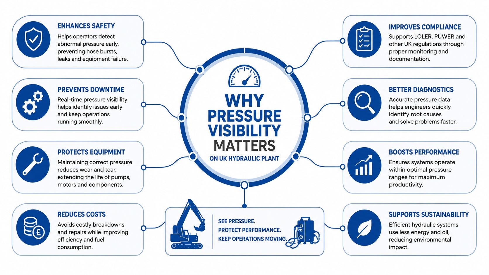
A pressure reading cuts straight through that uncertainty. If the discharge pressure is healthy but the actuator is still weak, you've got a local leak, restriction, or control fault. If the pressure never builds properly, the problem is upstream. That's why a modest transducer, fitted in the right place, often pays for itself far faster than a box of trial-and-error replacements.
Practical rule: don't diagnose hydraulic faults by feel. Put pressure on the machine and let the circuit tell you where the fault lives.
The value is even clearer when you look at the support equipment around the system. If you're checking a power pack build, a service engineer can cross-reference line protection and filtration needs with a resource such as Eaton hydraulic filter specs, then decide whether the issue is contamination, starvation, or control loss. Pressure monitoring doesn't replace that judgement, it sharpens it.
For anyone working on mobile plant, presses, or industrial hydraulics, the point is simple. Pressure visibility is the fastest way to turn a vague symptom into a structured fault-finding path, especially when the machine is too busy, too remote, or too expensive to strip twice.
What a Pressure Monitoring System Is
A pressure reading is not just a number on a dial. In a hydraulic circuit it tells you whether a pump is loading correctly, whether a valve is opening when it should, and whether the actuator is seeing the force the machine needs. A simple mechanical gauge still has a place because, on a live plant or power pack, a quick glance can tell an engineer far more than a guess ever will.
The history matters because it explains why the term covers more than one device. Bourdon's pressure gauge gave industry a practical mechanical way to see pressure, and later electronic sensing pushed that reading into the control system. Once pressure became a signal, operators could log trends, set alarms, and pass the value straight into a controller instead of relying on intermittent checks.
From a dial to a data chain
A pressure transducer works like a microphone, but for fluid force. It converts pressure into an electrical output that a display, PLC, recorder, or alarm unit can use, which is why the sensing head alone is never the full story.
A pressure monitoring system includes the sensing element, the signal conditioning, the display or controller, and the cable or network that carries the signal. If one part of that chain is poor, the reading becomes unreliable even when the transducer itself is sound. I've seen plenty of good sensors blamed for bad numbers when the fault was a poor earth, damaged cable, wrong output type, or a mounting point that was seeing spikes the rest of the circuit never felt.
The same principle shows up in other fields where the reading must be continuous rather than occasional. British hospitals have long relied on continuous arterial pressure monitoring in anaesthesia and intensive care workflows, and plant rooms and power packs need the same discipline when pressure changes fast. Intermittent checks can miss a fault completely if the circuit only misbehaves under load or during a short pressure spike.
A tidy sensor choice still matters, but it is only one part of the measurement chain. For a local check, a proper gauge from MA Hydraulics Ltd hydraulic pressure gauge options can be the right fit, especially on a manifold or test point where an operator needs a clear visual reading without extra wiring.
Modern systems cover a wide operating window, from 100 mbar to 1500 bar as noted in the pressure gauge technology history summary. That spread shows why the same broad technology family can serve low-pressure instrumentation and high-pressure hydraulics, while the hardware, mounting, and output choice change with the job. On connected plant, that often means the pressure point is also part of a wider check on machine health, which is why teams comparing flow and pressure behaviour sometimes look at tools such as Axis Meter Solutions submetering meters alongside the pressure hardware. The hardware changed, but the purpose stayed the same, tell the operator what the circuit is really doing.
Sensor Types, Outputs and Where Each One Fits
A UK buyer usually gets offered four broad sensor families, and they're not interchangeable. A mechanical gauge is still the right answer when someone needs a local check at the machine. Electronic transducers make more sense when the signal has to travel, be recorded, or drive a control action.
Matching the sensor to the output
| Sensor family | Typical output | Best fit | Key trade-off |
|---|---|---|---|
| Bourdon or diaphragm gauge | Visual readout | Local service checks on a power pack or manifold | No remote signal, no logging |
| Strain-gauge transducer | 4–20 mA or 0–10 V | General industrial hydraulics | Needs proper wiring and power |
| Piezoresistive or MEMS sensor | Ratiometric, analogue, CAN bus, or radio | Compact or connected systems | Can be more sensitive to installation quality |
| Ceramic-capacitive sensor | Analogue or digital depending on build | Aggressive media or where stability matters | Selection must match the fluid and process |
For long cable runs, 4–20 mA is still hard to beat because it tolerates electrical noise better than a simple voltage signal. 0–10 V is simpler to wire, but it's easier to upset in a noisy yard or around mobile plant. CAN bus fits modern mobile machinery because it sits naturally inside the vehicle network, while radio is useful when retrofitting a machine that wasn't designed for extra cabling.
The TPMS example is a good reminder that pressure alone is not always enough. In that system, the wheel sensor measures both pressure and temperature and sends the data by radio frequency to the receiver, which then forwards it into the vehicle network over CAN bus FCC TPMS documentation. That matters because temperature changes pressure, and without compensation you can mistake a thermal swing for a leak. The same logic applies to hydraulic reservoirs, case-drain monitoring, and warm-up behaviour on mobile kit.
If you're comparing transducers to other point-of-use monitoring tools, a resource like Axis Meter Solutions submetering meters is useful for seeing how electrical output, logging, and integration thinking carry across measurement disciplines. The point is the same. Match the output to the job, not the brochure.
For a quick local reference point, the hydraulic pressure gauge remains a practical benchmark when commissioning or troubleshooting a circuit.
Integrating Pressure Monitoring with Hydraulic Power Packs
On a power pack, where you tap the line matters more than how much you spent on the transducer. Put the sensor where it sees representative pressure, not where it only catches a transient spike or a dead volume. I've seen plenty of installations where the sensor was technically “installed”, but physically placed so badly that the numbers were close to useless.
Where to pick up the reading
A good location is often a manifold test point, the pump discharge line, or points before and after a directional valve. On actuator circuits, the port near the cylinder or motor can tell you whether the pressure loss is in the supply side or the load side. If you only measure at the pump, you can miss what the valve block or the actuator is doing.
That's where the rest of the circuit hardware matters. CETOP directional and proportional valves, modular sandwich valves, inline filters, flow dividers, and manifolds all create the physical structure that pressure tappings rely on. On many UK builds, those components are what give you a clean, serviceable place to fit a sensor without creating a maintenance headache.
The controller side is straightforward. A PLC or display reads the signal, scales it, and then decides what to do next. That might mean energising a proportional valve, sounding an alarm, or shutting the machine down if pressure goes beyond a safe limit. In a mobile machine, CAN bus or radio-linked sensors can remove hardwired loops altogether, which is changing retrofit work on agricultural and materials handling fleets.
A transducer is only as good as the circuit around it. Bad tapping points, loose cabling, and poor signal scaling will beat a premium sensor every time.
For retrofit work, a remote architecture starts to make sense, especially on machines that already have a crowded harness. If you want a practical route into that kind of setup, the remote monitoring systems resource is a useful reference point alongside the physical hydraulic build.
Choosing the Right Sensor for Industrial and Mobile Applications
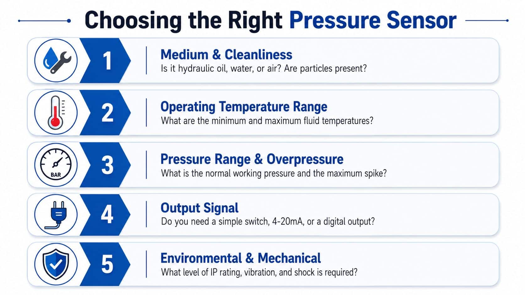
The right sensor choice starts with the fluid and the duty, not the catalogue page. Hydraulic oil, water, air, and contaminated media all behave differently, and the sensor has to tolerate the actual medium first.
A machine can look straightforward on paper and still punish a poor choice in service. In the field, I've seen sensors fail because the media was dirtier than expected, the pressure pulses were harsher than the spec suggested, or the body and seal materials were fine in theory but wrong for the circuit they were fitted into.
Five selection checks that matter on site
- Medium and cleanliness: Hydraulic oil is one thing, but if the circuit carries dirty fluid, water, or compressed air, the wetted parts and sealing must suit the media. A sensor that dislikes contamination will fail early, especially in older plant.
- Pressure range and headroom: Choose for the working pressure, then leave sensible margin for spikes. If the range is too low, you can clip transients or damage the sensing element.
- Dynamic response: Steady line pressure is easy. Fast spikes from accumulator discharge or valve shifting need a sensor and mounting arrangement that can follow the change instead of smoothing it away.
- Environment: Yard kit, wash-down zones, vibration, oil mist, and temperature swings all punish weak housings and poor sealing. Wrong IP protection usually means short service life.
- Electrical interface: Loop-powered, three-wire, analogue, CAN, or wireless each has its own place. The wrong interface makes commissioning harder and fault-finding slower.
A lot of buying guides stop at range and output. That is where they oversimplify. A pressure sensor can survive the spec sheet and still fail in practice because the machine vibrates, the wiring is noisy, or the mounting point traps air and damps the signal. The same logic applies whether you are building a new power pack or replacing a sensor on an ageing plant room manifold.
The modern piezoresistive family covers a very wide operating window, from 100 mbar to 1500 bar, which is why the same general technology can appear in low-pressure instrumentation and high-pressure hydraulics. That versatility does not remove the need for careful selection, it just broadens the options.
On UK power packs and mobile plant, the better question is often how the sensor sits in the measurement chain. A fast element with a poor tapping point, long lead-out, or badly chosen connector can perform worse than a more modest transducer mounted properly. Retrofit jobs usually expose that trade-off first, because there is rarely spare space, the loom is already crowded, and the existing manifold may only offer awkward access for a clean pressure take-off.
Installation and Calibration Best Practices
A good installation starts with a proper tapping point and ends with a reading you trust under load. If the sensor is fitted into a dead pocket, too far from the event you're trying to see, or exposed to uncushioned spikes, the data will mislead you even if the transducer itself is perfectly good.
The fitting sequence that avoids most grief
First, pick a representative line point and fit a proper boss with a clean seal face. Keep the sensor close enough to the circuit event that it sees useful pressure, but not so close that a hammering spike destroys it. A snubber or pulse-damping orifice can protect the element on harsh circuits.
Next, keep the tubing short, neatly routed, and free of sharp bends. Long runs and tight coils add delay and make the signal look softer than the system really is. Entrapped air is the worst offender here, because it makes the reading sluggish and unstable.
Practical rule: if the line isn't bled properly, don't trust the first reading.
For calibration, I'd always start with a two-point check against a reference gauge at zero and roughly 80 per cent of range. That gives you confidence in both offset and span without pretending the whole curve is perfect. The deeper check, though, is dynamic. Clinical monitoring literature stresses that fast-flush testing is needed because the system's frequency response can distort readings even when the transducer is working correctly PubMed clinical pressure monitoring review. The same lesson applies to hydraulics. A steady pressure comparison tells you the number is plausible, but a pressure step tells you whether the whole measurement chain can follow a real event.
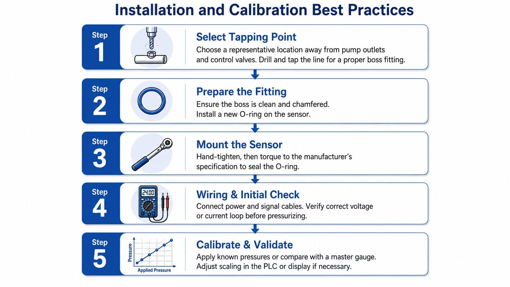
Document the zero, span, and calibration date, then keep it with the machine record. That habit matters on quality-managed UK sites, because pressure values are only useful if the team knows when the chain was last verified.
Common Troubleshooting Scenarios in the Field
A gauge that sits high at rest usually means one of two things. Either the relief valve is stuck or mis-set, or the transducer has drifted and needs a zero check. The quickest test is to compare the electronic reading with a trusted mechanical gauge at the same point, then isolate the valve block if the numbers disagree.
A slow pressure decay after shutdown is a different fault story. That usually points to an internal leak past a directional valve, a cylinder seal, or another load-holding component. The machine might still work, but the pressure won't stay where it should, and that's how drift creeps into everyday operation.
Three faults worth memorising
- Noisy or oscillating signal: Most often caused by air in the line, a worn snubber, or electrical interference on a long analogue cable. Bleed the circuit, check the damping, and inspect the cable route.
- Gauge and controller disagree: Usually a wiring fault, scaling error, or analogue-to-digital issue. Confirm the loop current or voltage at the controller before replacing the sensor.
- Spike on cold start: Often a sign that the circuit is seeing a startup surge the monitoring chain wasn't set up to handle. Check the tap point, damping, and start-up sequence.
The internal paperwork on a service call often leads straight back to components such as valves, seals, pumps, and filters, because those are the parts that create or hold pressure. A useful reference for fault-finding method is the troubleshooting methodology resource, especially when you're moving from symptom to root cause on a busy site.
The main thing is not to assume every bad reading means a bad sensor. In the field, I've seen more bad installations than bad transducers.
Where Pressure Monitoring Pays Off Across UK Industry
Agriculture, materials handling, and manufacturing all use pressure differently, but they all benefit from knowing what the circuit is doing before it fails. On tractors, loaders, and implement hydraulics, pressure trends can reveal blocked filters and failing remote valves before the work stops in the field. On forklifts, telehandlers, and dock loading systems, the same data helps teams spot wear early enough to plan maintenance instead of sending out a recovery truck.
In manufacturing, presses, machine tools, and automated lines rely on pressure to prove process capability and keep cycles repeatable. A pressure trend that starts to sag can flag pump wear, contamination, or filter loading long before scrap becomes obvious. That's where monitoring moves from “nice to have” to a direct production control tool.
A lot of older UK kit still runs on analogue gauges and periodic checks, and that's where retrofit work now makes sense. Recent work on IoT-enabled digitisation of traditional pressure chart recorders shows the direction of travel toward connected monitoring, while wireless and wearable pressure research points to systems that are becoming easier to deploy in awkward locations Nature pressure monitoring research. The practical takeaway for plant and fleet owners is straightforward. Keep the hardware simple where you can, connect it where you must, and measure pressure at the point that tells you something useful.
If you want help matching a sensor, gauge, manifold, or power pack to a real machine rather than a generic brochure spec, call 01724 279508 today or send a message through MA Hydraulics Ltd.